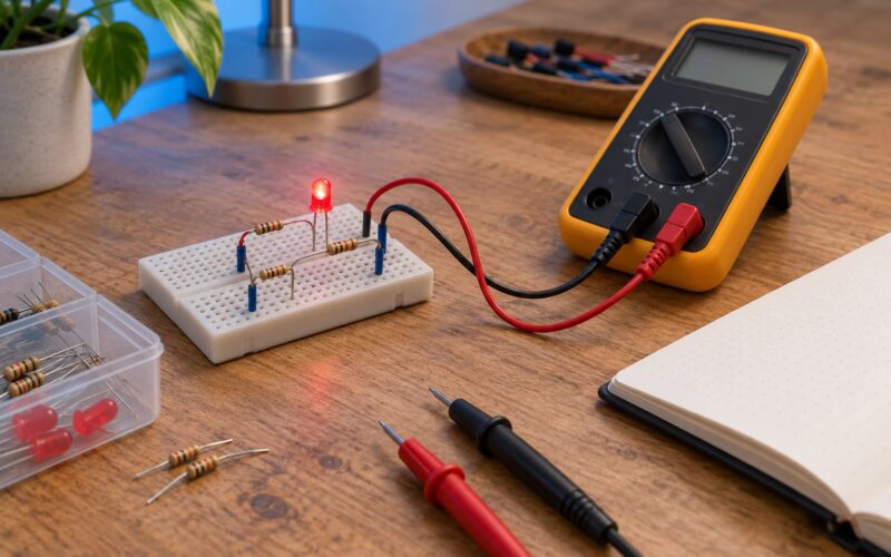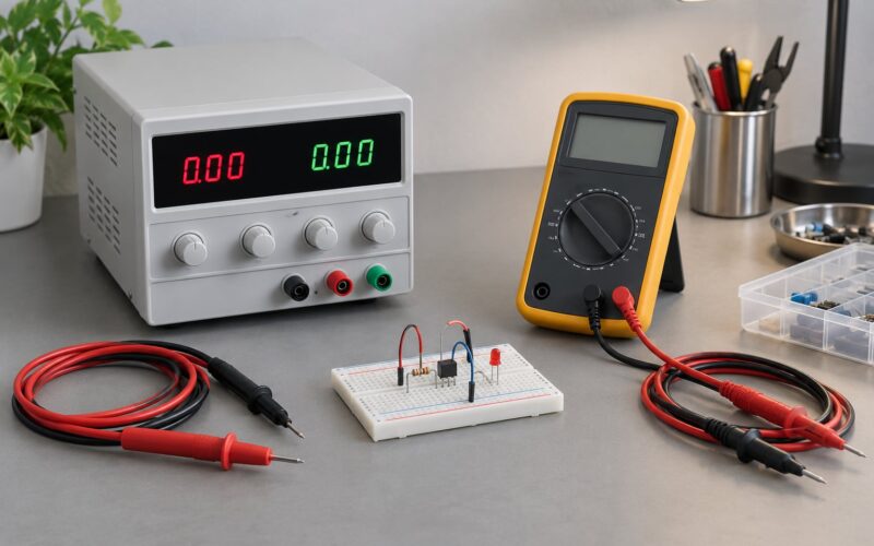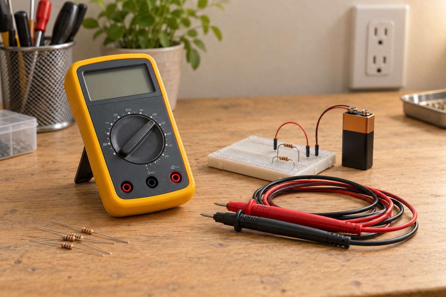
A multimeter is a single handheld instrument that measures voltage, resistance and current, and those three numbers answer most beginner questions about a circuit: is the power rail alive, is this component the right value, is this wire still connected. Learning multimeter basics for electronics beginners is mostly about two habits, picking the right mode and connecting the probes in the right place, and both take an afternoon to get comfortable. Everything below runs on batteries, USB supplies and breadboards, well away from anything connected to mains.
Table of Contents
- What Is a Multimeter Used For?
- Multimeter Basics for Electronics Beginners: Parts and Controls
- What the dial symbols mean
- Auto-ranging vs manual-ranging
- How to Choose a Multimeter for Beginner Electronics
- How to Use a Digital Multimeter Safely
- What the CAT ratings mean
- How to Measure DC Voltage
- Multimeter Basics for Electronics Beginners: Measuring Resistance
- How to Test Continuity and Identify a Broken Wire
- How to Measure Diode and Transistor Behavior
- How to Measure DC Current Without Frying the Meter
- A Simple Beginner Troubleshooting Workflow
- Common Multimeter Mistakes and How to Avoid Them
- Frequently Asked Questions
- Can I use a multimeter on household mains electricity?
- What does OL mean on a digital multimeter?
- Can I measure resistance while a circuit is powered?
- What is the difference between continuity and resistance mode?
- How do I test a battery with a multimeter?
- Which multimeter setting should I use to measure current?
- Conclusion: Practice on Low-Voltage Circuits First
What Is a Multimeter Used For?
A multimeter measures AC voltage, DC voltage, resistance, continuity, and on most meters current plus capacitance, frequency, diode forward voltage and temperature. It replaces the guesswork in a circuit you cannot see, which is why it is the first tool most people buy.
The three core measurements work differently and that difference is the whole game. Voltage is measured in parallel, across two points, with the circuit running. Resistance and continuity are measured with the circuit de-energized, across a component or a wire. Current is measured in series, so the circuit is deliberately broken and the meter becomes part of it.
A cheap test light or non-contact voltage detector tells you yes or no. A multimeter gives you a number, so you can tell a 4.7V rail from a 4.2V rail, or a 470 ohm resistor from a 4.7 kilohm one with the color bands faded by sunlight.
Multimeter Basics for Electronics Beginners: Parts and Controls
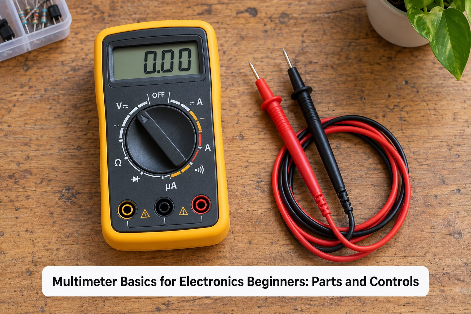
Most meters you will meet have five working parts. Knowing where each one is takes about two minutes and removes most of the confusion new users report about dial symbols and ports.
- Display: usually a backlit LCD showing digits, a minus sign, a decimal point and a small symbol for the active mode. Data hold freezes the reading so you can look at it with the probes still in place.
- Rotary selector: the central dial that chooses what the meter measures and, on manual-ranging meters, which range.
- Input jacks: usually three sockets at the bottom. The black lead usually goes in COM. The red lead goes in the V/ohmHz jack for almost everything, and only moves to the current jack when you are measuring current.
- Test leads: the probes themselves, insulated except for the metal tips. Finger guards set a few centimetres back from each tip keep your hands away from live conductors.
- Function buttons: on entry-level meters these select secondary functions such as diode test, continuity or backlight once the dial is already in the right group.
What the dial symbols mean
The symbols are international, so the same glyph means the same thing on any brand. You will meet a few more on meters with extra features.
| Symbol | Meaning | Where the probes go |
|---|---|---|
| V with a straight line over a dashed line | DC voltage | In parallel, circuit powered |
| V with a wave | AC voltage | In parallel, mains circuits only with a CAT III or CAT IV meter |
| Ω | Resistance | Across one component, circuit off |
| Diode symbol (triangle with a bar) | Diode forward voltage | Across the diode, black lead on the anode |
| Speaker or tone symbol | Continuity beep | Touched together or across a wire, circuit off |
| A | DC current | In series, circuit broken, red lead in the current jack |
| Two parallel lines of unequal length | Capacitance | Across the capacitor, circuit off and discharged |
Auto-ranging vs manual-ranging
An auto-ranging meter picks its own range and you only choose the measurement. A manual-ranging meter also makes you choose the range, so picking one too low gives you an overload reading and picking one too high gives you a meaningless digit. Beginners almost always prefer auto-ranging, because it removes a decision that has nothing to do with the actual circuit.
Manual ranging still has one place where it shines: resistance in the megohm range, where you are chasing a moisture problem or an insulation fault. It also costs a fraction as much, so a manual-ranging meter is a reasonable second purchase for someone already comfortable with the basics.
How to Choose a Multimeter for Beginner Electronics
For beginner electronics work, choose auto-ranging, at least a 4000-count display, a fused current input, and a safety certification mark from a recognised testing lab such as UL, ETL or CE. That is the shortlist. Everything else is optional.
- Display count: a 4000-count meter shows 3 useful digits plus a leading zero, which covers 9V battery checks and 5V rail measurements without range juggling.
- Continuity beep: a fast audible test beats reading digits when you are probing 30 PCB pads in a row.
- Diode test: one forward-bias LED test tells you polarity and roughly the forward voltage, which is how you identify a resistor from a diode.
- Lead Alert: some meters buzz or show a warning when a lead is in the wrong jack for the selected mode. That one feature prevents the single most common beginner error.
- Backlit display: matters more than beginners expect when you are working inside an enclosure or under a dashboard.
- True-RMS: only worth paying for if you will measure non-sinusoidal waveforms from variable frequency drives, dimmer circuits or switching supplies.
- Low impedance (LoZ) and AutoV modes: these add a low load to the circuit being measured, which kills ghost voltage on open cables. Useful, not essential at the start.
Skip the meters with no certification mark regardless of how many features they list. A meter that cannot be trusted on a bench is a liability, and forum threads keep turning up budget meters that measure well on a bench and badly in the hand.
How to Use a Digital Multimeter Safely
The safest multimeter is one used only on de-energized circuits, and the fastest way to build that habit is the live-dead-live method. Check the meter on a source you know is live, check it on a source you know is dead, then check your actual target. If the known-live source reads nothing, you have found the problem and you are holding a zero-volt reference.
- Work de-energized first. Unplug the supply and discharge capacitors before any resistance, continuity or diode measurement.
- Never measure resistance on a powered circuit. The meter’s internal battery fights the circuit’s supply and you get nonsense readings or a damaged meter.
- Watch your jacks. The red lead belongs in the V/ohmHz port for voltage and resistance, and only in the current jack for current.
- Inspect the leads. A nicked probe tip or a cracked insulation is a shock hazard. Replace it rather than working around it.
- Keep fingers on the guards. Hold the probe by the insulated barrel, never by the metal tip.
- Match the meter to the job. Mains work needs a CAT III 600V or CAT IV meter, and current measurement needs a properly rated high-energy input fuse.
- Know when to stop. Anything beyond a battery-powered circuit on your bench belongs to a qualified electrician or technician.
What the CAT ratings mean
The CAT rating tells you what kind of environment the meter was tested for. It is not a voltage rating alone: CAT IV is the origin of the power line, CAT III is distribution equipment, CAT II is plug-in wall outlets.
| Category | Typical environment | Beginner example |
|---|---|---|
| CAT I | Electronics only, no mains connection | Bench supply, Arduino board, USB cable |
| CAT II | Plug-in loads, local appliance wiring | Wall outlet, extension cord |
| CAT III | Distribution panels and fixed installation | Fuse box, wall switch, panel breaker |
| CAT IV | Origin of the mains supply | Service entrance, meter base |
One detail beginners miss: a meter rated CAT III 600V and one rated CAT II 600V are not equivalent, even though the voltage figure is identical. The higher category survives the switching transients that appear closer to the source.
How to Measure DC Voltage
Measure DC voltage by selecting the DC voltage range, plugging the black lead into COM and the red lead into the V/ohmHz jack, and touching the probe tips across two points without breaking the circuit. A healthy 5V rail reads about 5.0.
- Confirm the circuit is powered and confirm where you expect a voltage to exist.
- Set the dial to DC voltage, a range above the value you expect if the meter is manual-ranging.
- Insert the black lead into COM and the red lead into the V/ohmHz jack.
- Touch the black tip to the point you treat as the reference, usually ground or the negative terminal.
- Touch the red tip to the point under test. This is a parallel connection.
- Read the value, then reverse the probes if the answer to your question is negative.
A minus sign means the probe is reversed, not that something is wrong. Swap the probe tips and the sign goes away. If you measure between two points that should have the same voltage and you get a large difference, you have just found where the supply collapses.
A reading that drifts or flickers on a breadboard usually means a poor connection rather than a bad component. Reseat the parts and press down on the rails; breadboard contacts degrade fast.
Multimeter Basics for Electronics Beginners: Measuring Resistance
Measure resistance across a component with the circuit completely unpowered and at least one of the component’s terminals lifted off the board. A resistor that reads its colour-band value is good; OL means open, and near zero ohms means shorted.
To test a known resistor: read its colour bands, set the dial to the ohm symbol, hold the probes on the two ends, and compare the display with the value on the band. A 10 kilohm resistor should read about 10 kilohm, and if you select a manual range of 200 ohm it will show OL instead.
Two results matter more than the number itself:
- OL or a reading of 1 means open circuit. Nothing is conducting.
- A near-zero reading means short circuit. Something is conducting far more than it should.
Leaving the component soldered in the board is the classic error. Resistance readings in-circuit read low because your probes see parallel paths through neighbouring parts, so a resistor can look shorted when it is fine. Lift one leg, or accept the in-circuit reading only as a rough check.
How to Test Continuity and Identify a Broken Wire
The continuity test beeps when the probes are joined by a conductor, so it is the fastest way to check a fuse, a switch, a wire or a PCB trace. Touch the probe tips together and the meter should beep immediately; if it does not, the mode, the leads or the meter is the problem, not your circuit.
Read the display rather than relying on the sound alone:
| Reading in continuity mode | What it means |
|---|---|
| 0.0 to a few ohms, with a beep | Good connection, conductor intact |
| OL, or 1 on a manual-range meter, no beep | Open circuit, broken wire or failed switch |
| Reading climbs slowly or flickers | Intermittent fault, or a marginal contact |
A beep is evidence of a conducting path, not proof that everything is healthy. A wire can beep and still have high resistance along its length, and a switch can pass continuity on one throw and fail on the other. Always test both sides of a switch, both terminals of a fuse, and both ends of a cable.
On a PCB, use continuity to scan traces from pad to pad and from a pad to its connector pin. Finding one section that reads open while the rest of the trace reads good tells you exactly where to look for a cracked copper or a bad solder joint.
How to Measure Diode and Transistor Behavior
In diode mode the meter pushes a small current through the part and reports the voltage drop it needs, so a healthy silicon diode reads roughly 0.5 to 0.8 and an LED reads about 1.8 to 3.2 depending on its colour. With the black lead on the anode and the red lead on the cathode you should get a forward-voltage number; swap them and you should get OL.
For LEDs, that single reading identifies polarity: the lead that produces a forward-voltage reading is the anode, the long leg on a fresh part. The forward voltage also hints at the colour band: near 2.0V is red or amber, near 3.0V is blue or white.
Transistors need three measurements, not one. Treat an NPN transistor as two diodes back to back: base to emitter in one direction, base to collector in the other, both giving a diode drop, while emitter to collector reads OL both ways. Results that do not follow that pattern mean the part is suspect, though a socketed transistor is usually the real problem.
One caution: a good diode reading does not prove the surrounding circuit works. A perfectly healthy diode in a circuit that has no supply still sits there reading fine.
How to Measure DC Current Without Frying the Meter
Current must flow through the meter, so you break the circuit, insert the meter in the gap, and select DC current. Get that wrong and the meter takes the full short-circuit current through its input fuse, which is the mistake behind most blown-fuse multimeter repairs.
- Power off and disconnect the supply.
- Select the DC current range, the highest one first if the meter is manual-ranging.
- Move the red lead to the current jack, marked with a 10A or mA symbol, and keep the black lead in COM.
- Open the circuit at a point where you can insert the probe tips: unplug a jumper wire or lift one component lead.
- Power the circuit back on and read the current in amperes or milliamps.
- Power off, return the red lead to the V/ohmHz jack, and close the circuit.
A battery and one LED makes a clean first test. Put the meter in series with the LED, and you should read a few milliamps instead of the 10 to 20 mA a typical small LED pulls at 5V through a 220 ohm resistor.
Two more habits worth building. The high-current 10A jack is often unfused on some meters and rarely used, so keep short-duration measurements there and use the fused mA jack for anything sustained. And remember burden voltage: the meter itself drops a small amount of voltage in series, usually around 0.2 to 0.3V at low current, which matters when you are working near a rail voltage.
A Simple Beginner Troubleshooting Workflow
When a circuit does not work, work in this order: power, input, sections, components. Splitting the circuit into smaller pieces and measuring each one takes minutes and avoids replacing good parts by guessing.
- Confirm the source. Measure at the battery or supply output before touching the circuit. A 9V battery reading 7.4V is the answer, not a wiring fault.
- Measure at the input. Check the rail where the circuit begins. If the rail is dead, everything downstream is dead and you have already found it.
- Divide into sections. Break the circuit into two or three blocks and find the last point where the correct value is still present. The fault is always after that point.
- Test components one at a time. Resistance, continuity, then diode mode. Lift one leg of anything soldered in.
- Record the readings. Write down what you measured, not what you assumed. A photo of the display saves a lot of repeated probing.
- Change one thing at a time. Swapping two components or two wires at once guarantees you learn nothing.
Two electronics-specific cases are worth adding. On a PCB, cold solder joints show up as a trace that reads good to the pad but OL to the connector pin, and a reflowed joint fixes it. On a microcontroller board, check the power rails first, then I2C pull-ups with the power off, then each sensor output at 3.3V or 5V logic levels; a PWM signal reads as a steady average voltage between zero and the rail, so a mid-level reading on a PWM pin usually means the pin is working.
Common Multimeter Mistakes and How to Avoid Them
Almost every damaged beginner meter comes from one of a handful of errors. Each of these has a straightforward fix.
- Measuring resistance on a powered circuit. Remove power and discharge capacitors first, every time.
- Measuring current in parallel. Current goes in series. Parallel means a dead short through the input fuse.
- Leaving the red lead in the current jack. This is how beginners accidentally put mains voltage into the current input. Move it back when you finish.
- Confusing AC and DC. Selecting DC on an AC source gives a meaningless reading. Check the source before you select the mode.
- Choosing too low a range on a manual-ranging meter. Pick the next range up, or accept OL and go one step higher.
- Touching a metal probe tip while probing. Hold the guards, not the tip.
- Assuming a beep proves a component is good. A beep only proves a conducting path exists.
- Testing components without lifting a leg. Parallel paths make healthy parts look faulty.
- Probing a mains circuit with a CAT II or CAT I meter. The rating has to cover the environment, not just the voltage.
- Ignoring a flickering reading. Unstable numbers on a breadboard usually mean a loose contact, not a strange component.
- Leaving a capacitor charged. A stored charge can damage the meter and hurt you.
- Losing track of the COM rule. The black lead stays in COM in every measurement mode except when you are testing nothing at all.
- Reversing probes and panicking. A negative reading means a reversed lead, not a fault.
- Working on a battery you believe is dead. Check it with DC voltage first, every single time.
Frequently Asked Questions
Can I use a multimeter on household mains electricity?
Only with a meter rated for it, and only if you are trained. Household outlets sit in the CAT II category and fuse boxes in CAT III, so a CAT III 600V or CAT IV meter is the minimum you should even consider. Most beginners should leave mains work to a qualified electrician and practise on batteries and low-voltage DC supplies, where the same skills transfer directly.
What does OL mean on a digital multimeter?
OL means over-limit or open loop, and the meter is telling you the value exceeds the range you selected. In resistance and continuity mode it usually means nothing is conducting, so an open circuit or a broken wire. A manual-ranging meter shows a 1 in the leftmost digit instead. Select a higher range and the reading reappears.
Can I measure resistance while a circuit is powered?
No. The meter’s internal battery applies a small voltage, and a powered circuit fights it, giving you wrong numbers or damaging the meter. Switch off the supply and discharge any capacitors first. For a component still soldered in, lift one leg so the meter is not measuring parallel paths through neighbouring parts.
What is the difference between continuity and resistance mode?
Continuity mode tests one thing: is there a conducting path, yes or no, with a beep as the answer. It uses a fixed test level so a healthy wire reads close to zero ohms. Resistance mode measures the actual value in ohms, which is what you want for resistors and for spotting high-resistance or marginal connections.
How do I test a battery with a multimeter?
Set the dial to DC voltage with a range above the battery’s nominal voltage, put the black lead in COM and the red lead in the V/ohmHz jack, and read across the terminals. A fresh 9V alkaline should read about 9.3 to 9.6V, while a 9V battery below roughly 7V is finished. Match the reading to the chemistry, since rechargeable cells sit lower than alkaline ones.
Which multimeter setting should I use to measure current?
Use the DC current setting, marked A with a straight line over a dashed line, and move the red lead from the V/ohmHz jack to the current jack. Start on the highest range, insert the probes in series with the circuit, then step down until the reading is meaningful. Continuous measurements belong on the fused mA jack, not the 10A jack.
Conclusion: Practice on Low-Voltage Circuits First
Start with three drills and they carry everything else. Measure a 9V battery in DC voltage, confirm a known resistor in resistance mode with one leg lifted, then probe both ends of a spare wire in continuity mode until the beep makes sense. Multimeter basics for electronics beginners are built from repetitions like those, not from memorising symbols.
Keep the black lead in COM, keep the red lead in the V/ohmHz jack except when you are measuring current, and leave mains circuits to a qualified electrician. Once those habits are automatic, reading the manual for any unfamiliar feature takes a couple of minutes.