To know how to inspect solder joints, run two checks in order: a visual check under 10x magnification or a stereo microscope, then an electrical continuity check with a multimeter. Appearance tells you about wetting, fillet shape and mechanical strength; the meter tells you whether the joint actually conducts. Neither one alone is enough, because a bright joint can still be cold and a dull joint can still work.
This guide covers the bench workflow I use on prototype and repair work, and it is written for someone who has never been taught a formal inspection method. You can do the whole thing at a kitchen table with a loupe, a light and a meter. A production line does the same checks faster, with AOI and X-ray doing the parts your eyes cannot reach.
On production boards, the acceptance criteria usually come from a published standard such as IPC-A-610 or J-STD-001, and the bar rises with the product class. But for a first inspection, you are really looking for a short list of physical things, and they are learnable in an afternoon.
Table of Contents
- What You Need to Inspect Solder Joints
- Step-by-Step
- How to Inspect Solder Joints Visually
- Check the Solder Joint Mechanically
- Verify Electrical Continuity
- Inspect Surface-Mount and Through-Hole Joints
- Fix or Rework Defective Solder Joints
- Common Mistakes
- Why a dull joint can still be fine
- When to Replace the Joint or Component
- Frequently Asked Questions
- What magnification is best for inspecting solder joints?
- What does a good solder joint look like?
- How can I tell if a solder joint is cold?
- Do I need a multimeter to check solder joints?
- Can I inspect solder joints while the circuit is powered?
- Conclusion
What You Need to Inspect Solder Joints
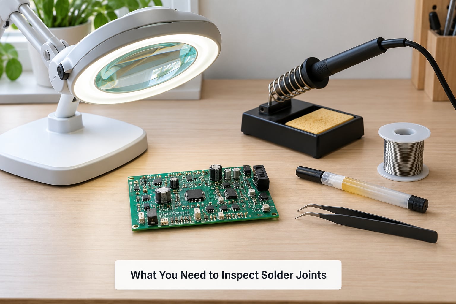
Start with light, because most missed defects are lighting problems rather than eyesight problems.
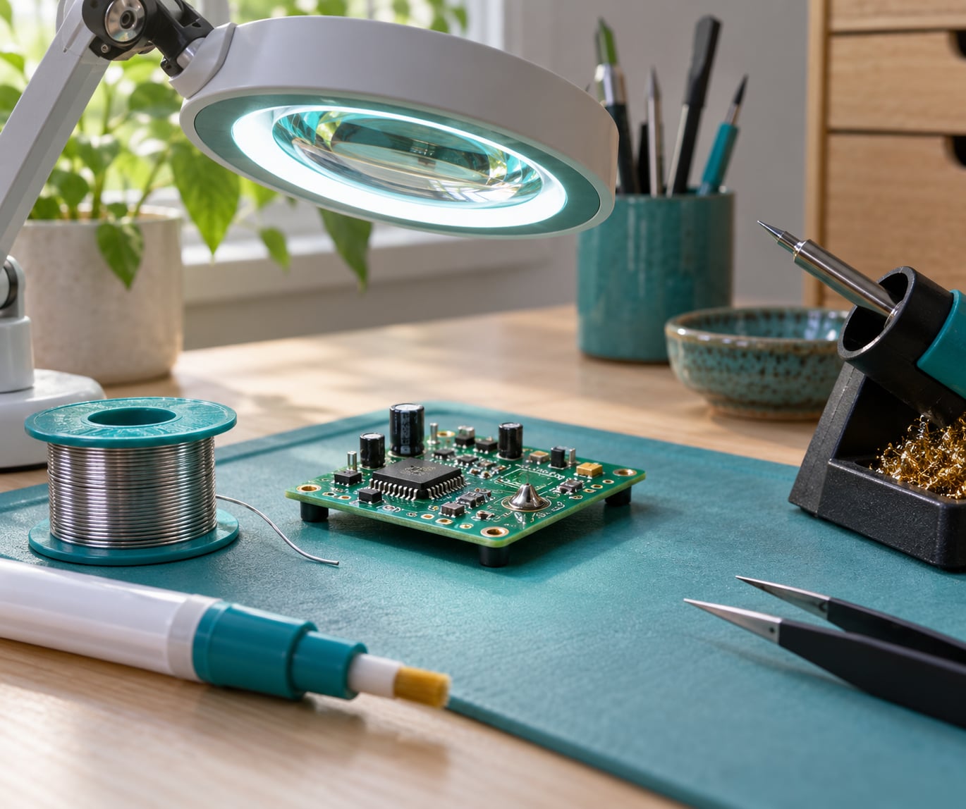
- Directional light. A small lamp or LED that you can move around the board. Hold it low, almost grazing across the surface, so that cracks, pits and fillet contours cast shadows. Overhead room lighting produces glare off shiny solder and hides exactly what you are looking for.
- Magnification. A 10x loupe or a 10x measure magnifier handles most through-hole joints and clear SMT work. A stereo microscope earns its bench space once you are dealing with fine-pitch packages, lifted pads or rework.
- Multimeter. Any meter with a continuity mode will do. A meter that also reads millivolts and ohms helps when you are chasing an intermittent joint.
- Cleaning supplies. Isopropyl alcohol at 90% or higher, cotton swabs, and lint-free wipes. Inspect joints before you clean them once, then clean and inspect again, because residue and corrosion are easy to mistake for a defect.
- Wooden toothpick or a plastic pick. For the gentle mechanical probe. Nothing metal, nothing sharp.
- Soldering iron, solder and flux, if you intend to fix what you find. A temperature-controlled iron set near 340°C for leaded work is a reasonable default; lead-free alloys need more heat, usually 370 to 380°C.
- Board documentation, when you have it. A schematic or assembly drawing tells you which pins are grounds and which are signals, which decides whether a bridge matters.
Step-by-Step
The rule underneath all of this is the one practitioners repeat most: the joint fails or works based on heat transfer, not on how much solder you added. Get the pad and the lead hot enough that the solder melts on its own and wets both surfaces, and the joint will usually be fine. Touch solder to a cold lead and you get a cold joint no matter how shiny it looks.
Work through the following in order. Do not skip to the electrical step because a board happens to work right now.
How to Inspect Solder Joints Visually
Hold the board so you can see the joint from at least two angles, one of them nearly edge-on. Solder defects hide on the far side of a component body and in the shadow it casts. This is the stage of how to inspect solder joints that catches the most defects, and it costs nothing but patience.
Look for these, in this order:
- Wetting. The solder should have flowed onto both the pad and the lead, forming a smooth, slightly concave fillet that meets both surfaces without a sharp boundary. A distinct bead of solder sitting on the pad with a sharp line where it touches the lead is non-wetting, and it usually means the pad or lead was dirty, oxidised or already plated poorly.
- Coverage. On a through-hole joint you want a complete, even ring of solder around the lead where it exits the board, with no gap and no exposed wire strands poking through.
- Surface finish. Freshly reflowed solder is bright and smooth. A dull, grainy, sandpaper-like surface suggests the solder never fully melted, or it was disturbed while cooling.
- Cracks. Run the light at a grazing angle across the fillet. A crack shows up as a dark line with a shadow on one side, and it is a reject even on an otherwise beautiful joint.
- Bridging. Solder that touches a neighbouring pad or pin. On a fine-pitch IC this is a short circuit, and it can sit underneath the package where you cannot see it at all.
- Insufficient solder. Not enough solder to form a continuous fillet around the lead. The joint may conduct today, but it has almost no mechanical strength and will fail the first time the board is flexed.
- Excess solder. A fat blob is not automatically a defect, but a big blob can hide a crack underneath it, bridge to a neighbour, or reach the next pin without touching it. Look at the shape, not just the volume.
One honest caveat about the bright-and-shiny rule: it is a useful first filter, not a verdict. Plenty of working joints are dull because they were coated in flux residue and never cleaned. Clean the board first, then judge the surface.
Check the Solder Joint Mechanically
Lightly touch the lead of a through-hole component with a wooden toothpick and nudge. The lead should not move at all in the solder. If it wiggles, flexes or feels gritty, the joint has an internal defect that looks fine from the outside.
Be conservative. Do this on through-hole leads and large terminals, not on small surface-mount parts or fragile package leads, where sideways force can snap a pad or a bond wire. On SMD joints, mechanical confidence comes from the fillet geometry and from the electrical test rather than from poking.
Verify Electrical Continuity
With the board unpowered, set the multimeter to continuity or lowest-resistance mode and test across the connection you care about.
- Probe from the component pin to the pad, the via, or the far end of the trace.
- A beep or a low resistance reading means the path conducts.
OLor a high reading means the joint is electrically open, and no amount of good-looking solder changes that.- On a suspicious joint, wick a little solder off with braid and re-test. If it opens up, you have found a joint that was only conducting through a crack in the fillet.
Also test the neighbouring pin for a short. If two pins that should be isolated beep together, you have a bridge.
Keep the caveat in mind: a joint can pass continuity and still be mechanically weak. Continuity proves current can flow. It says nothing about how many heat cycles or how much vibration the joint will survive.
Inspect Surface-Mount and Through-Hole Joints
Through-hole joints are forgiving. Look for a complete fillet, no cracks and some solder on the component side of the board.
Small chip passives, mainly 0402 and 0603 parts, are where soldering goes wrong most often. The two tell-tales are a concave, gently sloping fillet on the lead side, and no visible dry-paste or solder spatter on the ceramic body. Anything lumpy on top of a chip part is usually a problem underneath.
For gull-wing packages such as QFP, sweep the whole row of leads and check every foot for wetting, then look for bridging along the row at roughly 10x. QFN and LGA parts have no visible leads at all, so you are limited to checking the package perimeter, the wetting at the edges and the general appearance of the body.
For connectors, headers and power terminals, focus on solder volume and mechanical strength. These joints take mechanical load, so insufficient solder here matters far more than a cosmetic imperfection on a signal pin.
Hidden joints under BGA packages cannot be inspected optically at all. That is what X-ray inspection exists for, and if you are not equipped for it, verify those parts electrically or by thermal imaging under load instead.
Fix or Rework Defective Solder Joints
Reworking a marginal joint is low-risk if you work carefully, so it is usually cheaper than debating whether it will fail.
- Fix the cause first. Clean the pad and lead with isopropyl alcohol and a swab, and remove any old solder with wick. A joint that failed from contamination will fail again.
- Apply fresh flux. It is what lets the solder wet the surface, and skipping it is the most common cause of a second failed attempt.
- Heat the pad and the lead together with the iron, then feed fresh solder into the joint rather than onto the tip. The solder should melt and flow across both surfaces on its own. If it balls up and sits there, the pad is still too cold.
- For a bridge, remove it with wick and a clean iron tip, or drag a fine strand of solder through the gap while the joint is molten to wick the excess away. Take solder wicking between neighbouring pins as a sign the spacing is too tight for hand rework.
- Let the joint cool without touching it. Then clean, inspect again under magnification and re-test continuity.
Common Mistakes
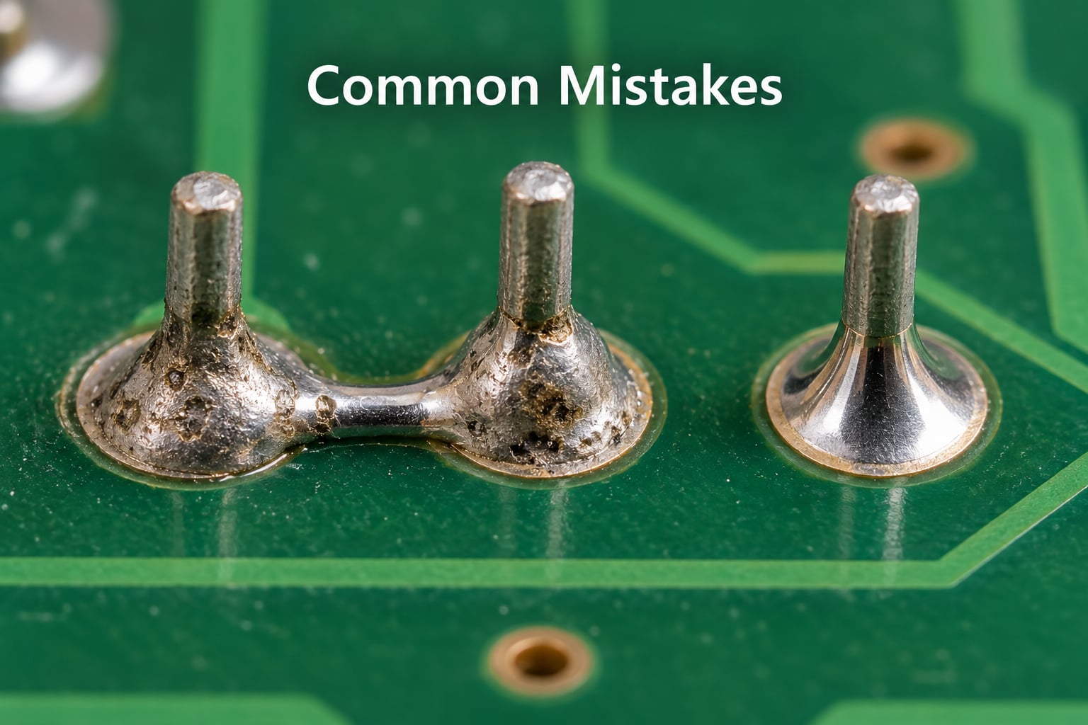
Most bad inspections come from a handful of habits, and learning how to inspect solder joints properly is mostly a matter of avoiding them.
- Judging by colour alone. Bright is a hint, not a result. Clean the board, check the fillet shape and check the wetting before you accept or reject.
- Inspecting from one angle only. Rotate the board. Defects concentrate on the hidden side, and a fixed viewing angle guarantees you will miss the same ones every time.
- Skipping the clean. Flux residue, dust and mild corrosion all look like a bad joint. Clean first, inspect twice.
- Flatten lighting. Uniform overhead light kills the shadows that reveal cracks and fillet contour. Move the light around.
- Assuming a working board has good joints. Intermittent faults live in joints that pass a quick function test today. Cold joints in particular can make contact intermittently, which is far more expensive to chase later than a reflow now.
- Overheating during rework. Holding the iron on a pad for long stretches lifts the pad or the trace. Lift frequently, and if a pad starts to move, stop.
- Confusing cosmetic issues with defects. A slightly fat but fully wetted fillet on a hobby board is not a failure. Prioritise joints that are electrically open, cracked, bridging, or mechanically loose.
Why a dull joint can still be fine
On older boards, corrosion dulls the solder surface across an entire area even though the joints underneath are solid. Look at the shape of the fillet and whether it wets both surfaces. If it does, and the meter beeps, the joint is working and cleaning it with a stiff brush and isopropyl alcohol is enough.
When to Replace the Joint or Component
Some damage is past a reflow.
- The pad lifted from the board. It moves with the lead or shows copper lifted from the laminate. Reattaching it means a trace wire to another pad, and professional rework is usually the sane call.
- The trace lifted or thinned. Repeated reheating weakens copper. If a joint needs reworking for a third time, the problem is heat, not solder.
- The board is contaminated under the solder mask. Burnt flux, moisture or a burned board does not re-solder reliably. Cleaning and re-evaluating the whole area comes first.
- The component is damaged. Overheated ICs, cracked ceramics and lifted component leads cannot be fixed with more solder.
- The same location fails repeatedly. Repeated failures point at stress, thermal expansion or a mechanical cause, not at the joint itself. Something about the design needs to change.
On a production line, any of these is an escalation rather than a bench decision. Handled wrong, rework damage turns a small defect into a scrap board.
Frequently Asked Questions
What magnification is best for inspecting solder joints?
A 10x loupe or 10x measure magnifier is enough for routine through-hole work and for reasonably clear surface-mount joints, and it costs far less than a microscope. A stereo microscope becomes worthwhile when you are inspecting fine-pitch packages, lifted pads or rework joints. Whatever you use, add a movable directional light, because cracks and fillet contours only show up when the light rakes across them at a low angle.
What does a good solder joint look like?
A good joint is bright or uniformly smooth, fully wets both the pad and the lead, and forms a slightly concave fillet around the connection. On a through-hole part you should see a complete even ring of solder where the lead exits the board, with no gaps and no exposed wire strands. There should be no cracks, no solder bridging to a neighbouring pin, and no sharp boundary where the solder meets the lead.
How can I tell if a solder joint is cold?
A cold or poorly wetted joint looks dull, grainy or oxidised, often convex rather than concave, and it may only be joined to the pad at one edge. Confirm it by reheating the joint with flux and the correct iron tip: good solder will re-flow and wet both surfaces immediately. If it stays dull, balled up or refuses to spread, the joint is cold or contaminated and needs cleaning before it is reflowed.
Do I need a multimeter to check solder joints?
A multimeter is not strictly needed for a visual inspection, but it is very useful whenever a joint might be open, shorted or intermittent. Set it to continuity, probe from the component pin to the pad or the far end of the trace, and remember that a beep only proves the path conducts, not that the joint is mechanically strong. A cold joint with a crack underneath can pass a test today and fail after vibration.
Can I inspect solder joints while the circuit is powered?
Visual inspection is safest and most reliable with the board unpowered, and it should be done that way. Powered boards glare, move when you probe them and risk shorting with your meter probes. If you must test live for an intermittent fault, use a current-limited supply, keep the meter on its highest voltage range first, and never probe a mains-connected board. Discharge capacitors before touching anything.
Conclusion
Power the board down, unplug it, and clean it. Then inspect solder joints one at a time under angled light and 10x magnification, checking wetting, fillet shape, cracks and bridges before you touch anything with a tool. Give the through-hole leads a gentle toothpick probe, run a continuity check on anything you are unsure about, and on any circuit you can reach with a meter.
Reflow what is cracked, cold, bridged or loose. Leave the merely imperfect joint alone, and let the electrical test settle the argument.
This workflow still holds in 2026, and it is the same one a production inspector follows, just slower and by eye.