BOM creation for electronics projects is the process of turning a finished schematic into a controlled, reviewable parts list that a factory or a workbench can actually build from. It usually takes a few hours for a small board and a day or two once sourcing and lifecycle checks are added, and the hardest part is not the export. It is filling in the fields the schematic cannot know for you.
A bill of materials is the document that quietly sets your cost, your schedule and whether the prototype is buildable at all. Hardware has no undo key, so a line that is vague when you release it becomes a wrong part fitted three weeks later.
Table of Contents
- What You Need
- Step-by-Step
- Step 1: Define the Project Requirements
- Step 2: Create the Initial Parts List
- Step 3: Complete Each Part Specification
- Step 4: Check Compatibility and Design Rules
- Step 5: Verify Availability, Cost, and Lifecycle
- Step 6: Add Sourcing and Substitution Rules
- Step 7: Review and Release the BOM
- Common Mistakes
- Frequently Asked Questions
- What is a BOM in electronics?
- What is BOM creation?
- Do I need a BOM to manufacture a PCB?
- What is the difference between a BOM and a schematic?
- Should a purchasing team be allowed to edit the released BOM?
- How do I make BOM creation easier on future projects?
- Conclusion
What You Need
BOM creation needs four things: a stable schematic, part data for every component, sourcing information, and a review pass by someone who did not build the file.
You also need to know which kind of BOM you are making. A preliminary BOM is a working list: quantities, reference designators and rough values, good enough to estimate cost and confirm the design is plausible. A production-ready BOM carries a manufacturer part number for every line, a complete footprint, sourcing detail, approved alternates and a revision number, and it is the version a contract manufacturer builds from.
Project requirements drive every entry you type. Ambient temperature, input voltage range, current draw, the interfaces you must support, the enclosure and the manufacturing method you have chosen all narrow the acceptable part list before you open a spreadsheet.
Step-by-Step
Step 1: Define the Project Requirements
Write the constraints down before the parts. Supply voltage and tolerance, maximum current per rail, the operating temperature range, the interfaces the board must expose, the target quantity, and the process that will assemble it, whether that is a pick-and-place line or a soldering iron and a pair of steady hands.
These requirements decide part selection directly. A rail that can swing from 9 V to 14 V rules out capacitors rated below 25 V, because a voltage spike on a supply that looks generous in the lab is a common cause of early field failures.
Check that you can answer one question per component: why is this part here, and what would break if it changed? Record the answer in a design note and the BOM entry has a reason behind it instead of a guess.
Step 2: Create the Initial Parts List
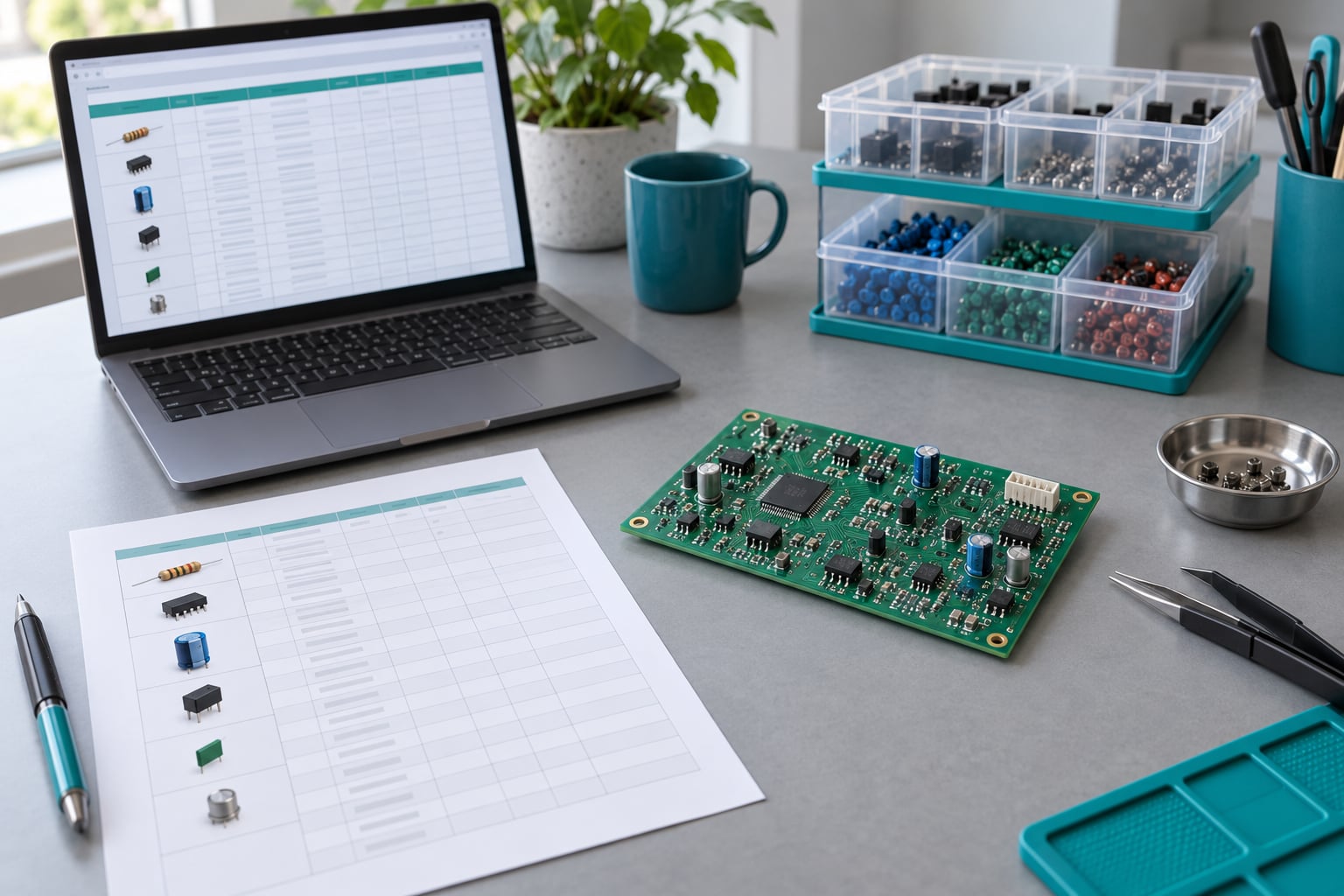
Export the list from your schematic capture tool rather than typing it by hand. Every major EDA tool can produce a line-item list, and the reference designators and quantities come across automatically, which removes the most error-prone part of the job.
A minimal first pass looks like this, and it is enough to sanity-check the design before you enrich anything:
| Quantity | Reference designators | Part number | Description | Package |
|---|---|---|---|---|
| 12 | R1 to R12 | RC0603FR-0710KL | Resistor, 10 kohm, 1 percent | 0603 |
| 1 | U1 | STM32G031K8T6 | MCU, ARM Cortex-M0+, 32 KB flash | LQFP-32 |
| 4 | C1 to C4 | CL10A104KB8NNNC | Capacitor, 100 nF, 50 V, X7R | 0603 |
Before you go further, count the parts against the schematic. If the resistor count does not match the number of resistor symbols, the export is picking up a stale revision, and everything you build on top of it inherits the error.
Step 3: Complete Each Part Specification
A useful BOM has a predictable set of fields. Some identify the part, others record engineering intent, and it helps to know which is which before you start filling cells.
| Field | Why it matters |
|---|---|
| Reference designators | Links the line to the silkscreen. R17 and R71 are not interchangeable. |
| Manufacturer part number | The only unambiguous identifier. Descriptions are not part numbers. |
| Quantity per assembly | Per unit, not per board batch, or a cost roll-up will be wrong by a factor of your build quantity. |
| Value, footprint, package | Package type and mounting style, SMD or through-hole, must match the PCB footprint. |
| Tolerance and voltage rating | A 5 percent resistor rarely works in a precision divider, and a 16 V cap is a poor choice on a 12 V rail. |
| Lifecycle status | Active, not recommended for new designs, or end of life changes what you can commit to. |
| Approved alternates | The parts procurement is allowed to use without asking you first. |
Treat the reference designator, part number, quantity and footprint as mandatory. Everything else is an engineering note that makes the file defensible later.
Step 4: Check Compatibility and Design Rules
Now compare the BOM against the design files, one source of truth at a time. Line up every footprint against the PCB layout and the assembly drawing, and check each part’s voltage and current rating against the schematic net it sits on.
Look for duplicate functions that should be consolidated, mismatched package types, and any part that is listed but not actually fitted. Then run your schematic design rule check and your PCB design rule check, and resolve anything they flag before you send the file out.
The check that works: every reference designator in the BOM exists on the board, and every reference designator on the board exists in the BOM. A difference in either direction is a real fault, and the list of designators is the fastest way to find it.
Step 5: Verify Availability, Cost, and Lifecycle
Each line needs a sourcing answer from an authorized distributor, not a marketplace listing. Confirm the manufacturer part number is current, get the minimum order quantity, the lead time and the price breaks that apply at your build quantity, and record the lifecycle phase.
One distributor listing is not proof that a part is a safe choice. A single-source part with a long lead time and a not-recommended-for-new-designs status is a schedule risk even when it can be ordered today, so record the risk rather than discovering it during the build.
Roll up cost per assembly once quantities are final. Multiply each line’s unit cost by its quantity per assembly, sum the result, and remember that assembly labour, test and packaging sit outside the parts total. Knowing the parts figure alone is how projects land well over the original estimate.
Step 6: Add Sourcing and Substitution Rules
Write down the rules for who can change a part, and what counts as an acceptable change. A good default: the purchasing team may swap a part only from the approved alternate list, and any change needs engineering sign-off before it is bought.
Be precise about the difference between an exact replacement and a substitute. An exact replacement is the identical manufacturer part number, or one you have tested and measured to be electrically and mechanically identical. A functional substitute meets the specification but is not identical, so it needs review of pinout, footprint, tolerance, temperature range and any timing or memory differences before it goes on the list.
Approved alternates should carry a note on what makes them acceptable, such as a same-footprint part with a higher voltage rating and a lower unit cost. A blank alternate cell tells the buyer nothing.
Step 7: Review and Release the BOM
Release means one agreed version that everyone uses. Assign a revision number, record the date and the author, freeze the approved file in a read-only location, and export it in whatever format the assembler, purchasing team or manufacturing partner asked for. CSV is the most widely accepted input, though spreadsheet files are more forgiving when someone has to sort or filter.
A short release checklist keeps this from turning into an argument:
- Every line has a manufacturer part number and a footprint.
- Reference designators match the schematic and the PCB layout exactly.
- Quantity is stated per assembly, not per order.
- Ratings meet the requirements recorded in Step 1.
- Approved alternates and change rules are attached.
- Revision number, date and author are recorded, and the file is frozen.
- Gerber data, pick-and-place coordinates and assembly drawings are released alongside it, matched to the same revision.
Small teams rarely need enterprise software for this. A shared folder with a dated revision, a named reviewer and a change log answers most questions at almost no cost, and it is a lot better than a file named final-v2-really-final.
Common Mistakes
Most BOM problems are omissions and misplaced parts rather than formatting. These are the ones that repeat, with the fix for each.
- Incomplete part numbers. A generic description such as 10 kohm resistor is not an orderable item. Symptom: the buyer guesses. Fix: require a manufacturer part number on every line before release.
- Incorrect footprints. The part is right and the pad pattern is wrong. Symptom: paste errors or unreflowable parts. Fix: verify each footprint against the PCB layout and the package drawing.
- Omitted tolerances and voltage ratings. Symptom: an out-of-spec part arrives and passes inspection. Fix: add tolerance, voltage and temperature columns and set a minimum for each line.
- Mixing manufacturer data with distributor listings. Symptom: a shortened or region-specific code gets quoted back. Fix: source the manufacturer part number from the manufacturer, then use distributors only for pricing and availability.
- Stale pricing. Symptom: the quote comes in well over the estimate. Fix: record the date of every cost lookup and refresh pricing before each build.
- Prototype and production quantities in one file. Symptom: someone orders 5000 resistors for a one-off build. Fix: keep per-assembly quantity as its own field and put order quantities in a separate column.
- Unapproved substitutions. Symptom: a part arrives that is functionally close but not equivalent. Fix: restrict changes to the approved alternate list and require engineering review for anything else.
- Undocumented non-modelled parts. Symptom: the boards arrive missing glue, labels or fasteners. Fix: add consumables and mechanical items as explicit lines with their own designators.
- Version drift between files. Symptom: the BOM, the Gerbers and the pick-and-place file come from different revisions. Fix: release them together under one revision number and never edit a released file in place.
Frequently Asked Questions
What is a BOM in electronics?
A bill of materials is a structured list of every component, part and material needed to build an electronics product. Each line typically carries a quantity, a manufacturer part number, the reference designators it covers, a package or footprint, and sourcing detail. It is the document a contract manufacturer or a maker uses to purchase parts and assemble the board correctly.
What is BOM creation?
BOM creation is the workflow that produces that list and keeps it accurate: exporting line items from the schematic, cleaning up duplicate or mislabelled entries, adding complete part specifications and approved alternates, checking ratings and footprints against the design, and releasing a reviewed file with a revision number. The export is the easy part. The checking is what prevents a bad build.
Do I need a BOM to manufacture a PCB?
Yes, and you need one well before manufacturing starts. A contract manufacturer cannot quote, buy parts or run an assembly line from a schematic and Gerber files alone, because those describe the board rather than the components. Assemblers also expect the pick-and-place file and assembly drawings at the same revision as the bill of materials, so a mismatch between them causes callbacks and re-quotes.
What is the difference between a BOM and a schematic?
A schematic is a drawing of the electrical design. It shows how components connect, but it usually leaves the exact part undecided, so several different resistors or capacitors can satisfy one symbol. A bill of materials is the purchasing list. It tells you precisely which part goes at each location, and it is what gets ordered, quoted and built. The schematic is the intent; the BOM is the commitment.
Should a purchasing team be allowed to edit the released BOM?
Not directly. The safest arrangement lets purchasing buy from the approved alternate list without asking, and requires engineering sign-off for anything else, which keeps change authority with the people who understand the circuit. Whichever rule you choose, write it into the file itself, because informal permissions are how two different part numbers end up in the same build.
How do I make BOM creation easier on future projects?
Keep a reusable template and a part library instead of starting from zero each time. Save your approved components as library entries with the manufacturer part number, footprint and approved alternates already filled in, then build new BOMs by importing from that library. This removes the recurring spreadsheet errors that come from retyping part data, and it keeps naming conventions consistent across every project.
Conclusion
Start at the schematic and the requirements, not at the spreadsheet. Build the list as a controlled document, validate every line against the design, and release only a reviewed version with complete sourcing data, change rules and a revision number.
Once that habit is in place, the bill of materials stops being the file nobody trusts and becomes the thing that tells you what the product costs and whether it can be built at all. That is the whole job, and it is worth doing properly on the first board.