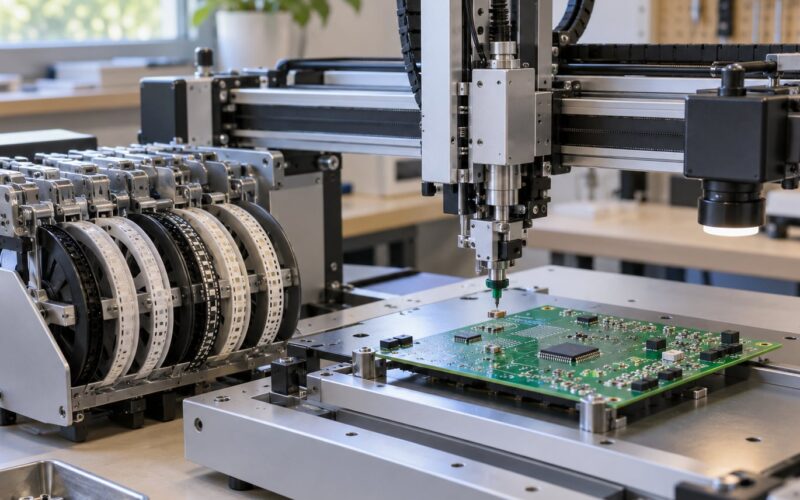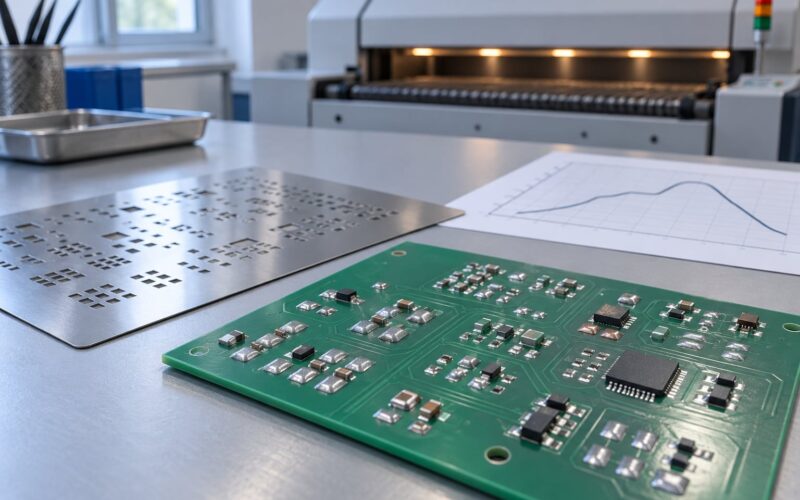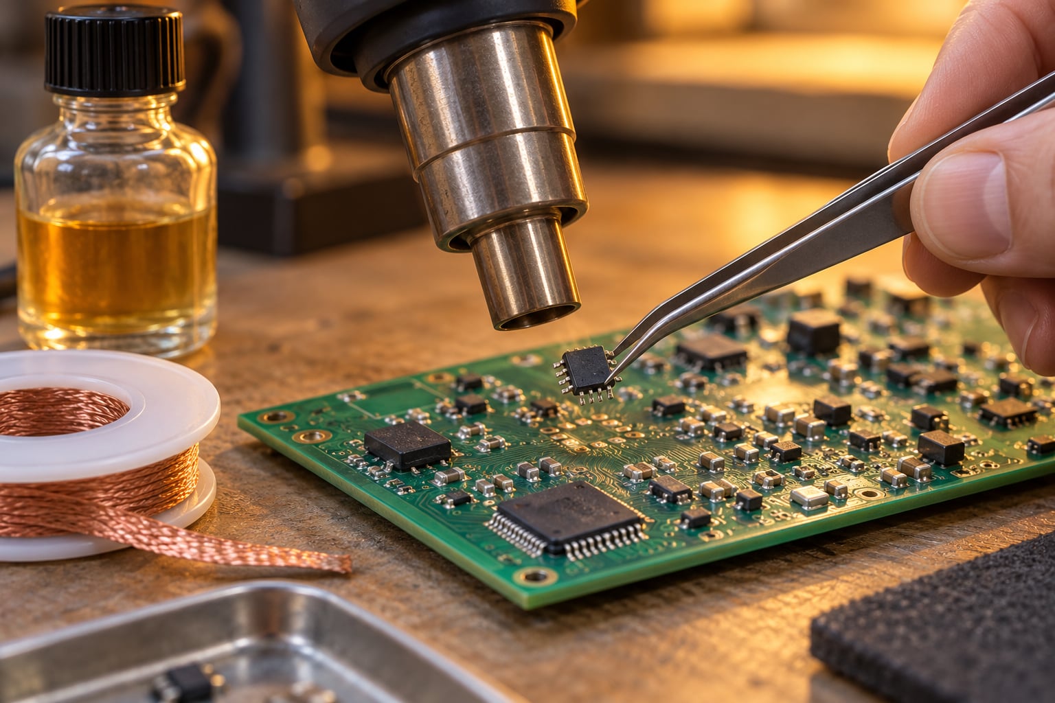
To desolder a surface mount chip, you heat every solder joint at the same time with a hot air rework station until the solder goes glossy and mobile, then lift the part straight off with fine tweezers. A 2-4 lead chip takes about five minutes; a 64-pin QFP on a multilayer board is a different job entirely. The whole technique is about applying even heat to the entire package and moving nothing until every joint has released.
Most damaged boards were not damaged by heat. They were damaged by impatience, or by too little of it. Get the process right and the chip comes off cleanly, the pads survive, and the board goes back into service.
Table of Contents
- What You Need
- Step-by-Step: How to Desolder a Surface Mount Chip
- 1. Inspect and Prepare the Board
- 2. Choose the Right Heating Method to Desolder a Surface Mount Chip
- 3. Apply Flux and Set the Temperature
- 4. Heat the Entire Package Evenly
- 5. Lift the Surface Mount Chip
- 6. Remove Residual Solder and Clean the Pads
- 7. Inspect and Prepare for Replacement
- A note on package choice, if the design is still open
- Common Mistakes
- Frequently Asked Questions
- What is the best tool for removing SMD components?
- Can you hand solder SMD?
- Can you solder surface mount components?
- Does isopropyl alcohol dissolve solder?
- Can I reuse a chip I removed from a board?
- When should I send the board to a rework specialist?
- Conclusion
What You Need
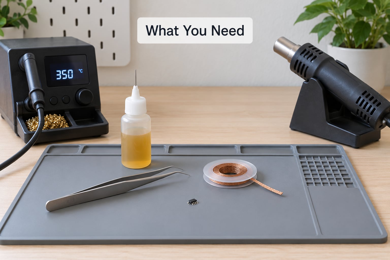
Six things cover almost every surface-mount removal job. Anything beyond that is specialty equipment for fine-pitch or ground-pad parts.
- A temperature-controlled soldering station. Not a fixed-temperature iron. You want a tip you can hold around 300-350C for SMD work, roughly 570-660F, and dial back for delicate passives.
- A hot air rework station with interchangeable nozzle tips if the part has more than about four leads. Hakko, JBC and Aoyue are the names most technicians ask for.
- ESD-safe tweezers. Ceramic or dissipative tips, narrow enough to grip a chip body without touching the leads.
- Flux. No-clean or tacky flux in a pen or syringe, plus a bottle of liquid flux for flooding a stubborn package.
- Desoldering braid (solder wick). Wide flat braid for ground pads, narrow braid for fine-pitch lands.
- Isopropyl alcohol at 90% or higher and a lint-free wipe, for cleaning flux residue off the pads afterwards.
Add a preheat plate or a hot plate if you regularly work on multilayer boards, and a microscope or jeweller’s loupe. Trying to judge whether a 0.4 mm pitch joint has cleared without magnification is guesswork.
On the hot air versus soldering iron question: use a soldering iron on two-terminal parts such as 0402, 0603 and 0805 chips, and on single-pin parts like a memory chip on a module. For anything with leads on four or more sides, hot air is faster and far kinder to the board. A big thermal pad on the bottom of a QFN or any BGA really only comes off with hot air.
Step-by-Step: How to Desolder a Surface Mount Chip
1. Inspect and Prepare the Board
Before any heat goes near the board, look at what you are removing. Note the package type, the lead pitch, whether there is an exposed ground pad underneath, and how close the nearest components sit to the chip body.
Take a photo from directly above with a scale reference in frame, or at minimum note the pin-1 dot. On a multi-pin package, pin 1 orientation is the single most common reason a replacement part lands backwards.
Clean the area first. A toothbrush and isopropyl alcohol, or a lint-free wipe with solvent, removes grime and old flux so you can actually see the joints. Disconnect power, and if the board came off a live device, discharge any large capacitors.
What success looks like at this stage: a dry, clean surface where you can count the leads and see the pad edges.
2. Choose the Right Heating Method to Desolder a Surface Mount Chip
Three methods cover almost everything. Hot air heats all leads simultaneously and is the default for SOIC, SSOP, TSSOP, QFP, QFN and BGA packages. A soldering iron makes contact with one joint at a time, so it suits small two-terminal chips where the whole part is barely bigger than the tip.
A preheat platform is not a removal method, it is a support method. Raising the board to 100-150C before you apply hot air keeps the far side of the board from acting as a giant heat sink, and it is the single most effective way to avoid a pad lifting.
The beginner-safe rule: if you have to ask whether to use hot air, use hot air. Special handling applies to a single large ground pad (slow the ramp, use a wide tip), a fine-pitch IC below 0.5 mm pitch (lower airflow, more patience), a plastic connector within a few millimetres (shield it with kapton tape or foil), and any multi-terminal package over 64 pins (preheat, then be patient).
3. Apply Flux and Set the Temperature
Flux is what makes the job possible. It dissolves the oxide film on the solder and the pads, it improves wetting, and it buys you working time. Sn63Pb63 solder melts around 183C and SAC305 lead-free around 217C, and flux lets you work a package at a tip or air temperature well below the pure melting point of the alloy.
There is no single universal temperature. For a small SOIC or TSSOP, start around 300-320C at the tip. For a large QFP or a multilayer board, 350C and slow movement work better. For a QFN with a thermal pad, add a small amount of solder to the pad first so you have a good thermal bridge.
Start at a lower setting and add heat if the solder will not move. Many people scorch a board by cranking the air to maximum because the solder refuses to melt, when the real problem is an oxidised tip that is not transferring heat at all.
Apply flux generously. Pin a pen to the pads, then flood the whole package with liquid flux. A shiny wet surface is what you want before heat goes on.
4. Heat the Entire Package Evenly
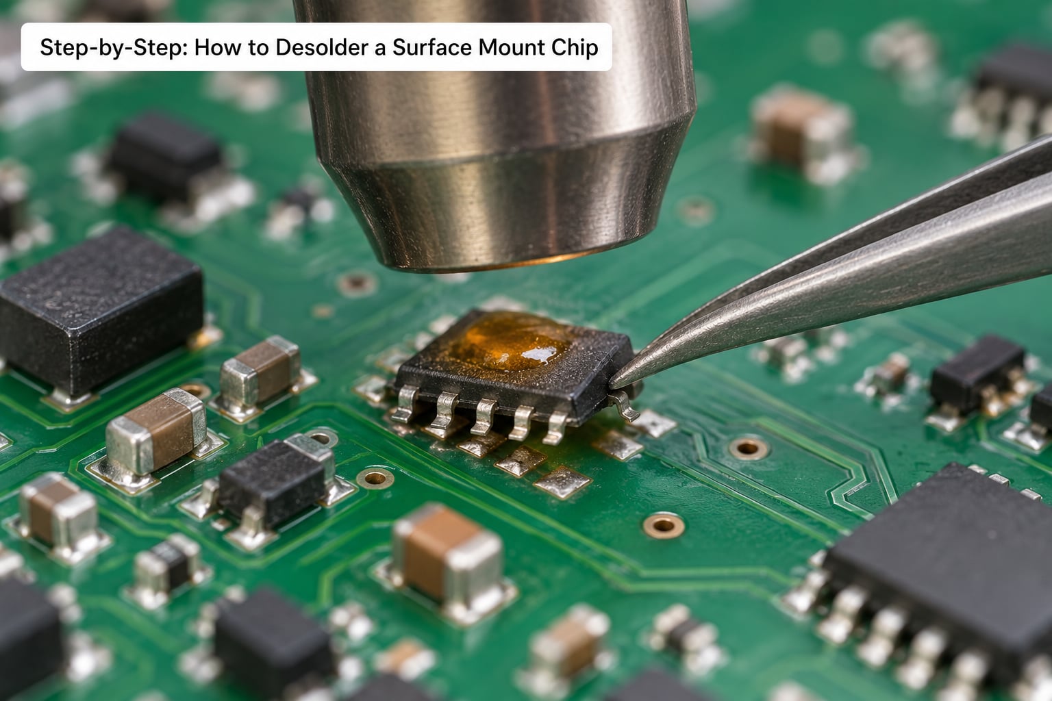
Pick a nozzle slightly wider than the chip body, so the hot air reaches both rows of leads at once. Hold the handpiece a few millimetres above the board and move it in a slow orbit across the package. Never touch the nozzle to the board, and never park it in one spot.
Watch the solder, not the clock. Two or three seconds of heat on a small package, up to ten or fifteen on a large one. The joints go from dull grey to glossy, then the solder starts to slump and pull inward toward the pads. That slump is your signal.
Stop the moment the component shifts slightly on its own under the airflow. That means the solder has released. If a nearby component such as a connector or an electrolytic capacitor starts to move or discolour, back the temperature down and shield the neighbour with foil or kapton tape.
5. Lift the Surface Mount Chip
Once every joint is molten, grip the chip at its centre of mass with the tweezers, not by a lead. Lift straight up, gently, without twisting. Twisting is what tears pads and traces off the laminate.
If it does not come free, put the tweezers down, add more flux, and heat again rather than pulling harder. A small vacuum pick (an airpick or a vacuum lifter) works well for larger packages where tweezers would twist the part.
A mechanical chip popper, which is a dowel with a bent wire fork, is a useful alternative on big parts: one light tap and the part comes free with zero rotational force.
Keep the board level or tilt it about 90 degrees so molten solder drains off the pads instead of wicking underneath the part. Store the removed chip in a labelled container; salvaged parts are worth keeping for failure analysis.
6. Remove Residual Solder and Clean the Pads
Even a clean removal leaves a film of solder on every pad, and a replacement chip will not sit flat on it. Flood the pads with fresh flux, lay the braid across them, press the iron tip onto the braid, and drag it slowly across the row. Lift and reposition for each pad rather than scrubbing back and forth, which can catch and peel the edge of a land.
On a big exposed ground pad, a broad tip and flat braid do the job faster than a narrow one. If solder still sits in a corner, controlled hot air with the braid held against it clears what an iron cannot reach.
Finish with 90% or higher isopropyl alcohol and a lint-free wipe. It removes no-clean flux residue and it does not dissolve solder, so the pads stay usable. Do not scrape pads with a blade or pick at them with a screwdriver. If the surface looks rough, re-tin it with fresh solder rather than trying to shave it flat.
7. Inspect and Prepare for Replacement
Put the board under magnification and check five things: every pad is present and flat, no trace has lifted, no solder ball sits between lands, no neighbouring component moved, and there is no contamination left on the surface.
Run a continuity check between adjacent pads and from each pad to its via or surrounding ground plane. A short here means leftover solder or a solder ball, and it will show up as a mystery failure after the new chip goes in.
Apply a small amount of fresh flux, then tine the pads with a thin coat of solder so the replacement part has something to bond to. Reflow the new chip on all four sides in turn, keep working until the joints look like slightly concave fillets, and clean again with isopropyl alcohol when it cools.
A note on package choice, if the design is still open
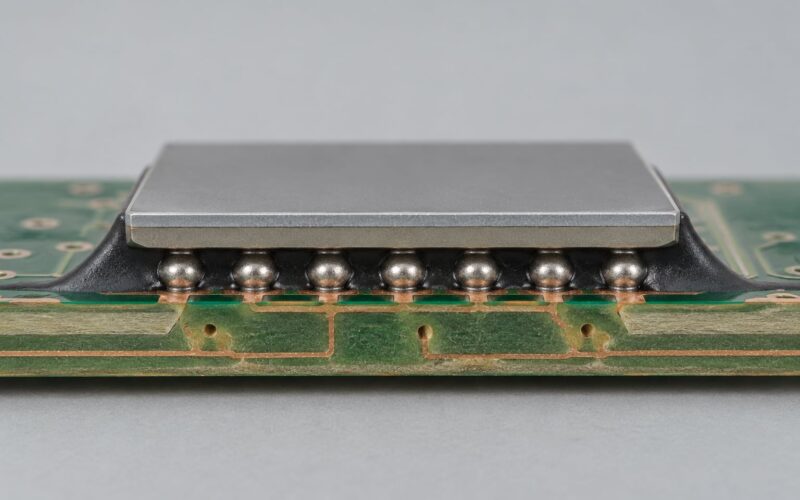
For a prototype that has not been laid out yet, this is a decision that pays off before anyone picks up an iron. Packages with a large exposed ground pad, and BGAs in general, are the hardest things to rework. A design that routes critical signals to a fine-pitch QFN with a thermal pad underneath will cost more in respins than one using a package with a longer pitch and no hidden underside connection. Reworkability is a packaging decision, not a rework-station decision.
Common Mistakes
Almost every failed removal traces back to one of these eight.
- Moving the part too early. You lift while one row of leads is still solid and twist the package off the board. Fix: wait for the solder to slump everywhere. Next repair: work the largest package on your board last, after your hand is warm.
- Insufficient heat. If you are struggling, the solder is usually not hot enough, or the tip is oxidised and not conducting. Fix: clean and re-tin the iron tip, add fresh solder to the joints, then add heat. Next repair: check the tip under magnification before blaming the board.
- Excessive airflow. A strong stream can blow a small chip across the bench or spin a part you have just released. Fix: drop to medium airflow and use a wider nozzle. Next repair: always start at low airflow and raise it only if the solder will not move.
- Overheating the board. Prolonged heat weakens the adhesive bond between the copper pad and the laminate, and the pad peels off. The 1 oz copper used on most two-layer boards has very little margin. Fix: preheat, move continuously, and work the shortest time that clears the joints. Next repair: check under the part for scorched solder mask afterwards.
- Skipping flux. Dry joints need more heat and more time to clear than fluxed ones. Fix: flux generously and re-apply whenever the surface stops looking wet. Next repair: keep a flux pen within reach of the board at all times.
- Tweezing a lead instead of the body. Gripping a pin gives you a lever right at the joint. Fix: grip the centre of the package. Next repair: practise the grip on a scrap board first.
- Letting solder wick under the part. Adding braid before the part is off traps solder beneath it, so the pads never come clean. Fix: remove the chip first, then clean. Next repair: hold the board at a slight angle so molten solder drains away.
- Confusing package types. Expecting a pin-cutting method to work on a part with a bottom-side ground pad, or setting a one-sided temperature for a two-sided package. Fix: identify the package and its underside features before applying heat. Next repair: iron-only and mechanical methods do not work on BGAs, and pin cutting will not free a part bonded through its thermal pad.
Frequently Asked Questions
What is the best tool for removing SMD components?
A temperature-controlled hot air rework station is the best tool for removing surface-mount chips with more than about four leads, because it heats every joint at once and lets you lift the part without twisting. A soldering iron is enough for two-terminal chips such as 0603 passives and single-pin memory chips. Desoldering braid cleans the pads afterwards rather than removing the part, and a solder sucker works on through-hole joints but poorly on SMD land patterns.
Can you hand solder SMD?
Yes. Hand soldering surface-mount parts is normal practice in repair and prototyping, and a good temperature-controlled iron plus flux plus steady hands handles two-terminal chips and SOIC packages comfortably. Fine-pitch parts below 0.5 mm and BGAs are realistic only with a fine tip, magnification, and steady air rather than a bench rest. Practise on scrap boards first, since the cost of a mistake is a pad you cannot easily replace.
Can you solder surface mount components?
Surface-mount components solder easily once the pads are flat, clean and tinned. A replacement chip goes on by applying flux, positioning it by its pin-1 mark, and reflowing one side at a time until the joints form slightly concave fillets. A weak joint looks like a shiny dome rather than a curve that flattens out at the edges, which means not enough heat or not enough dwell time on that side.
Does isopropyl alcohol dissolve solder?
No. Isopropyl alcohol at 90% concentration and above removes flux residue, oils and fingerprints without touching the solder, copper pads or solder mask, which is exactly why it is the standard final clean after rework. Lower concentrations pick up more water and leave a hazy film. Use it on a lint-free wipe, and let the board dry fully before applying power.
Can I reuse a chip I removed from a board?
Sometimes. A chip removed with hot air and plenty of flux, with every joint fully molten, often survives and can be tested in a socket or a new board. A chip pried off with force, heated aggressively, or twisted while pins were still attached usually has bent or fractured leads and is scrap. Treat any salvaged part as suspect unless you have a way to test it, and note the board it came from for failure analysis.
When should I send the board to a rework specialist?
Send the board out when the part is a BGA, when the die is bonded through a large exposed ground pad on a multilayer board, or when a pad or trace has already lifted. Those jobs need an X-ray or microscope, a controlled reflow profile and often stencil work, and a second attempt by hand usually makes the damage worse. High-value production boards and anything with impedance-controlled routing deserve the same caution.
Conclusion
Start by identifying the package and what sits under it, then protect the board with flux, a clean tip and steady, even heat across the whole package. Nothing moves until every joint has turned glossy and mobile, and the part comes straight off with no twisting.
Multilayer boards, fine-pitch ICs, ground-pad parts and BGAs are a different discipline. If that is what you are holding, or if a pad has already lifted, hand it to a rework specialist rather than trying a third time. The same applies at design stage: package choice and pad layout decide how hard the repair will be long before anyone picks up an iron.
Practise the sequence on a scrap board until the part comes off first try. The procedure is the same in 2026 as it was ten years ago, and the difference between a clean removal and a scrapped board is patience.