A bench power supply is a mains-powered instrument that hands you a DC voltage you choose and a current ceiling you set yourself, so every test happens under conditions you control instead of conditions you hope for. Power supply basics for electronics bench work come down to four ideas: voltage, current, a set current limit, and clean ground. Get those right and powering a board stops being guesswork. Get them wrong, and the usual outcome is a fried part and a supply you now distrust.
Table of Contents
- What Is a Bench Power Supply?
- What a bench power supply actually does
- How a bench supply makes regulated DC
- Linear and switching designs trade noise against efficiency
- How Do Voltage, Current, and Power Relate?
- Constant voltage and constant current modes
- Why the wattage rating is not what you multiply
- How to Choose the Right Bench Power Supply
- Voltage range and headroom
- Current capacity
- Adjustment resolution and the setpoint readout
- Reading a spec sheet
- How many outputs do you need
- Beginner bench or advanced bench
- Five tests to run before you trust any supply
- How Do I Use Power Supply Basics for Electronics Bench Work?
- Set the current limit before you connect anything
- The power-up sequence
- Shutdown
- Which Output Connection Should I Use?
- Is It Normal for a Power Supply to Be Hot or Noisy?
- How to Troubleshoot Common Power Supply Problems
- No output at all
- Unexpected voltage
- The supply is stuck in current limit
- Ripple and noise
- Intermittent connections
- When to suspect the supply instead of the circuit
- Frequently Asked Questions
- Can I use a bench power supply for a breadboard?
- Why is my power supply showing a current limit?
- Can I connect a bench power supply directly to a battery or motor?
- Should the negative terminal of a bench power supply be grounded?
- How do I measure the output voltage safely?
- Where to Start on the Electronics Bench
What Is a Bench Power Supply?
A bench power supply is a stable, low-noise, adjustable DC voltage source that is routinely current limited to protect the circuit under test. You set the voltage on the front panel, you set a current ceiling below what the circuit should ever draw, and the supply holds both values until something goes wrong.
That last part is the reason a bench supply exists. A wall adapter gives you one fixed voltage and no visibility into what the circuit is drawing. A bench power supply gives you a test source you can dial, watch and trust, which turns “it works when I touch it” into an actual measurement.
It is also the fastest tool you have for fault isolation. When a board will not boot, swapping the wall adapter for a known-good adjustable source answers a whole class of questions in about two minutes: is the problem upstream of the board, or in the board?
What a bench power supply actually does
- Sets an output voltage anywhere inside its rated range, typically in steps fine enough to hit 3.3 V or 5.0 V without guesswork.
- Sets a current limit that the load is not allowed to exceed, no matter what the load does.
- Survives a dead short or a mis-wired board by throttling itself instead of destroying the circuit.
- Meters the output voltage and the current actually being delivered, continuously and on the front panel.
- Acts as a known-good reference source when you suspect the power supply feeding a board is the faulty part.
- Replaces a suspect supply during repair work, so a dead adapter never stalls a diagnosis.
How a bench supply makes regulated DC
Mains power arrives as AC. A transformer steps it down and isolates it from the mains, which is the barrier that keeps a lethal voltage out of your circuit. Rectification and a filter capacitor turn the stepped-down AC into a raw DC rail.
From there the two topologies diverge. In a linear supply, a series pass element (typically a transistor with a heatsink) drops whatever voltage is left over, and a feedback loop compares a sample of the output against your setpoint and adjusts the pass element continuously to keep the error near zero. In a switching supply, a transistor chops the input at tens or hundreds of kilohertz, and a small inductor and capacitor filter the result into smooth DC.
Linear and switching designs trade noise against efficiency
A linear supply burns the difference between the input voltage and the output voltage as heat, so it is quiet and inefficient. A switching supply moves energy in pulses and is efficient, but switching residue lands on the output rail as ripple. This is the whole trade-off, and it is why hobbyists argue about it.
The Hackaday teardown of a budget switching bench supply measured roughly 200 mV peak-to-peak of switching ripple on the output, with almost no output filtering. Hobbyists running similar boxes in comments describe Riden-branded models at around 100 mV of noise, which is usable for digital work and useless for anything analogue.
| Design | Output noise | Efficiency and heat | Typical use |
|---|---|---|---|
| Linear | Microvolts to a few millivolts ripple | Low efficiency, large heatsink, hot in a small case | Low-noise analogue, RF, audio, precision reference work |
| Switching | Millivolts to hundreds of millivolts ripple | High efficiency, small and cool for a given current | Most prototyping, digital rails, general bench work |
| Budget rebrand | Often unstated, sometimes badly overstated | Varies; headline current rating can be optimistic | Learning to solder and first breadboards, with supervision |
The cheap middle path that experienced hobbyists keep recommending is a switching supply used as a pre-regulator ahead of a linear regulator, so the linear stage only ever burns a volt or two and the switching residue never reaches the load.
How Do Voltage, Current, and Power Relate?
Voltage is electrical pressure, measured in volts. Current is the flow of charge, measured in amps. Power is what happens when both are present, and it is simply voltage multiplied by current.
Multiply volts by amps and you get watts. That is the number that heats a part, drains a battery, or destroys a MOSFET you connected backwards.
| Typical bench job | Voltage | Current | Power |
|---|---|---|---|
| 3.3 V microcontroller rail | 3.3 V | 0.3 A to 1 A | 1 W to 3 W |
| 5 V development board | 5 V | 0.5 A to 2 A | 2.5 W to 10 W |
| Small signal or op-amp prototype | 9 V to 15 V | under 0.2 A | under 3 W |
| LED strip constant-current test | 12 V | 0.5 A to 2 A | 6 W to 24 W |
| Motor or solenoid load test | 12 V | 1 A to 5 A | 12 W to 60 W |
| Class-D amplifier bench test | 24 V | 2 A to 4 A | 48 W to 96 W |
Most circuits draw far less than you would guess at first. A microcontroller plus a few sensors on a breadboard sits under 200 mA, and a modern switching regulator feeding it draws even less at the wall.
Constant voltage and constant current modes
Every decent bench supply runs in one of two modes. In constant voltage, or CV, it holds the voltage you set and delivers whatever current the load asks for, up to your limit. In constant current, or CC, it holds the current you set and lets the voltage fall to whatever the load demands.
The crossover is automatic. If your load asks for more current than the limit you set, the supply abandons CV and drops into CC, and the front panel usually shows a CC indicator. That indicator is the single most useful thing on the display, because it tells you the circuit is pulling more than it should.
Why the wattage rating is not what you multiply
Multiply 30 V by 5 A and you get 150 W, which is how most suppliers advertise. The real limit is usually lower, because the transformer, rectifier and pass devices are sized for a fixed total output. Many hobby supplies hold roughly 100 W to 150 W across the range, and tap the current down as the voltage climbs.
| Set voltage | Current available | Delivered power |
|---|---|---|
| 5 V | 5 A | 25 W |
| 12 V | 5 A | 60 W |
| 30 V | about 3 A | about 90 W |
This envelope is why nobody serious powers a 5 V 3 A board and a 12 V 4 A motor from the same 30 V 5 A supply at full tilt, and why the manufacturer prints a small chart of current against voltage on the case rather than a single headline number.
How to Choose the Right Bench Power Supply
The shopping results for this search term are a wall of near-identical listings with wildly different numbers printed on them, which tells you the numbers alone are not going to help you. Judge a supply on range, on whether you can read its current setpoint before connecting anything, and on whether the maker publishes ripple and regulation figures at all.
Voltage range and headroom
Maximum voltage has to cover the highest rail you intend to build, with room to overshoot during testing. A 30 V supply covers 3.3 V, 5 V, 9 V, 12 V, 15 V and 19 V, which covers almost every breadboard and small motor project. A 60 V supply only earns its place if you work on switch-mode circuits or drive higher-voltage devices.
Current capacity
Size for the largest load, not the typical one. Motors draw a startup surge several times their running current, and that surge will pull a supply into CC mode if the limit is set too low, which looks like a fault and is not one.
For a hobby bench, 3 A to 5 A covers motors, solenoids, LED strings and small amplifier boards without a large footprint. Above 10 A you are buying bench volume you will rarely load, and you should be spending the difference on measurement gear instead.
Adjustment resolution and the setpoint readout
Resolution determines how precisely you can hit a rail. A supply with a coarse knob and a fine knob plus a three-digit display lands around 10 mV steps, which is workable for 3.3 V and 5 V work. An encoder with a four-digit display gives you the setpoint and the delivered current side by side.
That readout is not a luxury. If the panel cannot show you the current limit you have set before a load is connected, the only way to find out is to short the output and watch, which is exactly the behaviour beginners on r/AskElectronics complain about most. Display accuracy also deserves a footnote: a forum owner running a low-cost unit reported a voltmeter error near 3 percent against a reference meter, so trust the panel for setpoint and your multimeter for truth.
Reading a spec sheet
Most spec sheets publish eight numbers and most buyers read two of them. The rest are worth knowing.
| Specification | What it tells you | Reasonable value |
|---|---|---|
| Ripple and noise | Residual AC riding on the DC output, in millivolts peak-to-peak | Below 5 mV p-p for analogue work, tens of mV acceptable for digital |
| Load regulation | How much the output voltage moves as you add or remove load | Below 0.5 percent across the rated range |
| Line regulation | How much the output moves when the mains input sags or surges | Below 0.5 percent over the input range |
| Voltage accuracy | How close the setpoint is to the output at the terminals | Below 0.5 percent for lab work |
| Constant current range | How finely you can set the ceiling, and over what range | Adjustable down to tens of milliamps |
| Over-voltage and over-current protection | Whether the supply trips itself on a fault condition | OVP and OCP both present and adjustable |
| Output enable | A front-panel control that kills the output without unplugging | Present, ideally with a momentary switch |
Ripple is quoted in millivolts peak-to-peak, which is the distance from the highest point of the waveform to the lowest. A figure that is missing entirely should be read as unknown, not as good. Several budget supplies publish a maximum current but no ripple figure at all, and the ones that do publish it tend to have been measured by somebody else.
How many outputs do you need
A single channel covers most hobby work. Two channels let you build a split supply for op-amp work, which is how you run an amplifier from a single wall outlet. Three isolated channels cover digital, analogue and a negative rail at once, which is what most small bench development boards give you.
Beginner bench or advanced bench
| Consideration | First bench supply | Advanced bench supply |
|---|---|---|
| Voltage range | 0 V to 30 V | 0 V to 60 V or more |
| Current range | 0 A to 3 A or 5 A | 0 A to 10 A with a real power envelope |
| Output enable | Wanted, front-panel switch | Expected, plus remote sense |
| Setpoint readout | Voltage and current on the same display | Separate setpoint and delivered readings |
| Ripple and noise | Specified, under 20 mV p-p | Specified, under 5 mV p-p or explicitly linear |
| Protection | OVP and OCP with adjustable trip points | Sequencing, remote inhibit, sense leads |
| Control | Front panel only | USB or Ethernet with an SCPI command set |
| Budget priority | Spend on the supply, borrow measurement gear | Spend on a meter and scope, reuse the supply |
Five tests to run before you trust any supply
These work on a new supply, a used lab box from a hamfest, or a build of your own. I would run all five before anything expensive touches it.
- Output enable. Confirm the output actually goes to zero volts when the enable control is released, without unplugging anything. If it does not, that is the first thing you will miss during a fault.
- Setpoint readability. Read the current setpoint with nothing connected. If the panel shows the ceiling you configured rather than a blank or a maximum, the supply is telling you the truth about its own limits.
- No-load and loaded voltage. Measure the output unloaded with a meter, then attach a known load and measure again. The difference is load regulation in practice, and voltage that walks rather than holds is the rebrand complaint that comes up repeatedly.
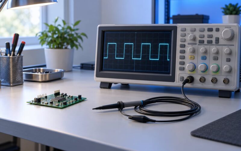
- Ripple. Put a scope probe across the output in AC coupling and read the peak-to-peak figure. Compare it against what the maker claims.
- Discharge behaviour. Turn the output off at a moderate voltage and watch the terminals. Output capacitance that bleeds away in seconds is safer; a rail that clings for minutes is an annoying surprise and a probe hazard.
How Do I Use Power Supply Basics for Electronics Bench Work?
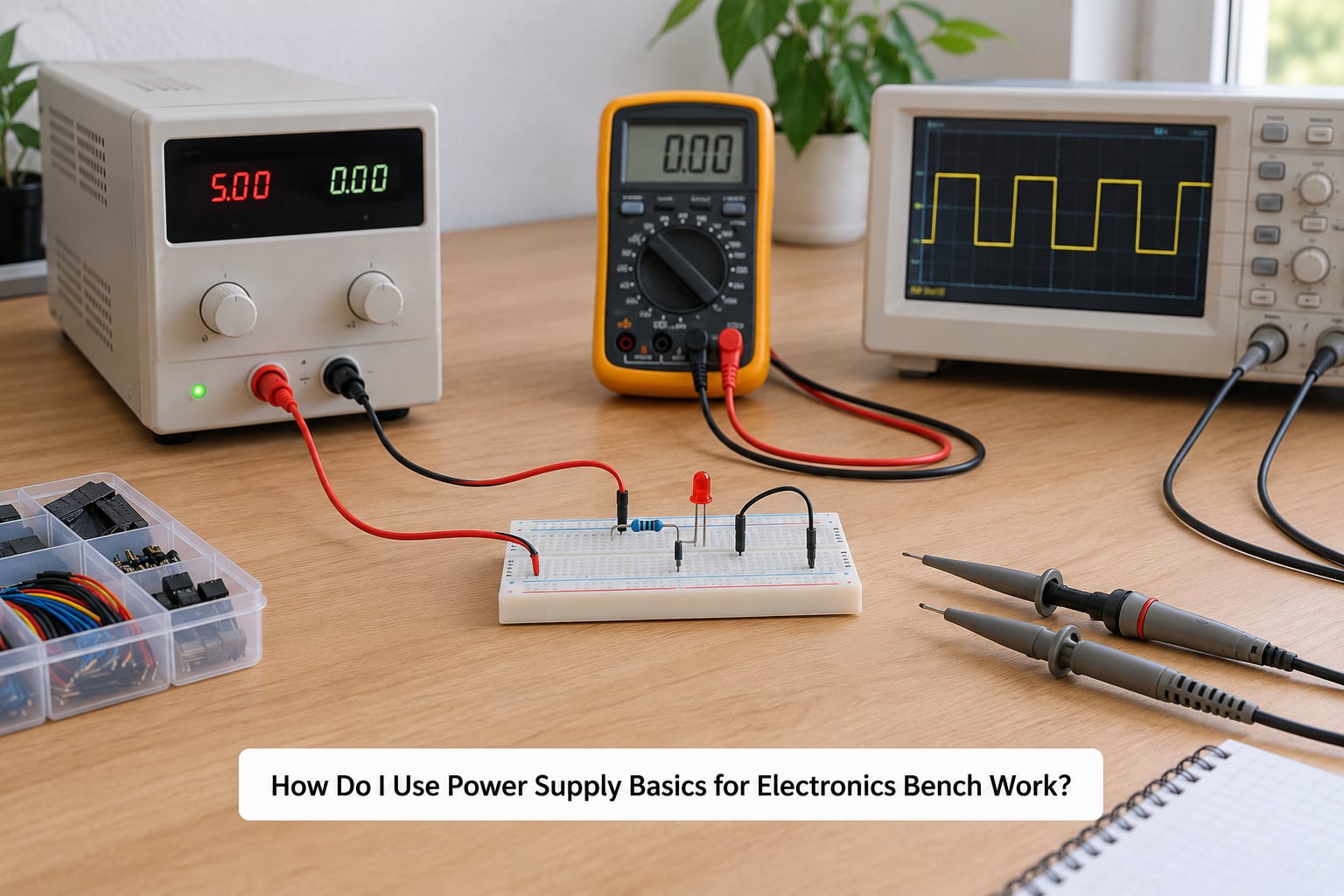
The whole procedure takes about two minutes and prevents almost every beginner casualty. Do it the same way every time, on every board, until it is automatic.
Set the current limit before you connect anything
This is the step nobody teaches and everybody learns the expensive way. You do not attach a board and then decide how much current it should draw. You decide first, and the board gets to prove you were right.
- With the output disabled, set the voltage to what the circuit needs. For a 5 V board, that is 5.0 V.
- Set the current limit below the expected draw. For a development board drawing a few hundred milliamps, 200 mA to 300 mA is a sensible starting ceiling; for an unknown circuit, start at 100 mA.
- Enable the output. The meter should now show a voltage near your setpoint and a current near zero.
- Connect the load across the terminals and watch the current reading climb.
- If the supply drops into CC mode immediately, the circuit is drawing more than you expected, or you wired something backwards. Disconnect before investigating.
- Raise the current limit deliberately, in steps, until the CC indicator stays out and the current settles.
Roughly double your limit at each step rather than jumping to a large value. A limit set at 5 A protects a board that needs 300 mA, and if a fault exists the board sees 5 A instead.
The power-up sequence
Work in this order and the order never matters again: confirm polarity at the circuit, set the voltage, set the current limit, enable the output, measure the voltage at the circuit terminals with a meter, connect the load, watch the current, and only then probe anything with a scope.
Measure at the circuit, not at the supply. Long leads and breadboard contacts add resistance, and a rail that reads 5.00 V at the supply can be 4.6 V at the far end of the board. That difference is often the actual fault you were hunting.
Shutdown
Reduce the current limit first, then the voltage, then disable the output, then disconnect. Disconnecting a load while the output is live invites arcing across the terminals, especially at higher voltages.
For a supply with a slow discharge circuit, expect the terminals to hold a charge after shutdown. Confirm with a meter before you touch a probe to anything.
Which Output Connection Should I Use?
Most bench supplies put 4 mm banana jacks on the front panel. That single connector type covers most of what you will meet.
Banana plugs mate with binding posts, and with the barrel sockets found on older laboratory gear. Banana-to-alligator leads are convenient for a one-off connection to a breadboard rail, and they are also the most common way to start a small fire, because cheap leads are frequently rated well below the current your supply can deliver. Check the rating printed on the moulded handle, and use leads rated for at least the maximum current of your supply.
Screw terminals appear on entry-level supplies and suit heavier wire with no plug to come loose. They are slow to use and permanent to wire up, which some people prefer. Barrel sockets exist for adapting to fixed DC leads; check the polarity convention and the centre pin versus sleeve connection before connecting anything, because they are not standardised across every manufacturer.
Whatever you use, keep the positive lead visibly separate from the negative one when the circuit is not connected. Reversed polarity is the second most common way a board dies on a bench, and a supply with an output enable switch makes it far less likely because you can power down before rewiring.
Do not daisy-chain leads to stretch a reach. Buy a longer lead. And never probe a powered circuit with a bare lead held in your fingers.
Is It Normal for a Power Supply to Be Hot or Noisy?
Some fan noise and some warmth are entirely normal. A switching supply drawing near full current runs its fan constantly, and a linear supply at low output voltage dissipates the dropped voltage as heat by design, which is why a large heatsink exists at all.
Normal means the fan runs continuously, the case is warm to the touch on the top or side, and the reading on the panel is steady.
Stop work and unplug if you see any of the following: a burning or fishy smell, a fan that has stopped while the supply is still loaded, discolouration or melting around the vents, a case hot enough to be uncomfortable to hold, arcing or a visible spark at a connector, or a voltage reading that jumps around with no load change.
Heat in a linear supply tells you something useful. If a 30 V supply delivering 5 V at 2 A is cool and one delivering 25 V at 2 A is very hot, that is just the physics: 25 V minus 5 V at 2 A is 40 W of heat in the pass transistor. A linear supply used this way wastes power deliberately in exchange for quiet output, which is a trade you make knowingly or not.
Intermittent fan noise paired with a stalling display usually points at a failing fan bearing, and the fix is a replacement fan, not a working supply. Undersized connectors, however, are a genuine fire risk rather than an annoyance, and a plug that has darkened needs replacing.
How to Troubleshoot Common Power Supply Problems
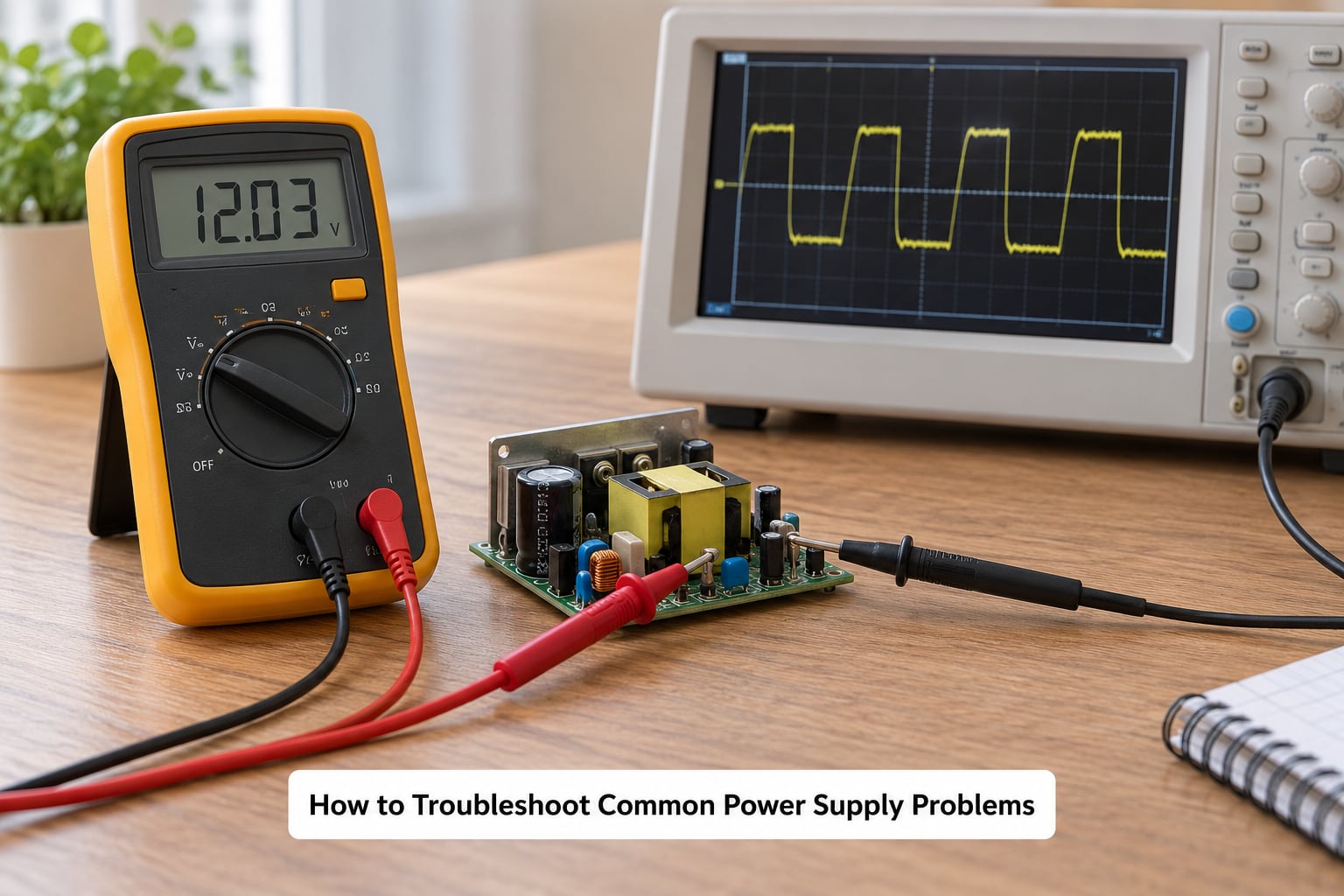
Work through the problems in the order below rather than jumping to conclusions. Each step assumes the previous one checked out, which saves a lot of time chasing a fault that was never in the circuit.
No output at all
Check the mains indicator, then the output enable control. If the supply has no output switch at all, that is the most common complaint about budget boxes, because cutting power means reaching behind the bench to the wall.
Next, confirm the setpoints are not sitting at zero. Then measure the terminals with a meter while the output is enabled. If the panel shows a voltage and the terminals show nothing, suspect a broken connector or a failed output stage rather than a settings problem.
Unexpected voltage
Compare three readings: the setpoint on the panel, the no-load voltage at the terminals, and the voltage under load. If the panel disagrees with a reference meter by more than a percent or so, the panel is the inaccurate part, and hobbyists report several percent of error on the cheapest models.
If the no-load voltage is correct but the loaded voltage sags, load regulation is poor and the setpoint is not being held. If the voltage drifts slowly on its own with nothing connected, that is voltage walk, a complaint that comes up repeatedly about budget units.
Also check that the current limit is not set so low that the supply sits in CC mode even at light load. In CC, the output voltage floats wherever the load puts it.
The supply is stuck in current limit
Constant-current mode means the load is asking for more current than you allowed, or the output is shorted. Disconnect the load and check whether the indicator clears. If it does, the circuit is drawing what it draws, and you need either a higher limit or a smaller circuit.
If the indicator stays on with nothing connected, the supply has a fault or the current limit control is miscalibrated.
Ripple and noise
Ripple is the leftover AC riding on the DC output, measured in millivolts peak-to-peak. To see it, put the scope probe across the output terminals, use the AC coupling on the vertical channel, and set the timebase so you see a handful of switching cycles. Set the probe tip to short ground spring mode so the ground clip does not turn into an antenna.
Excessive ripple on a switching supply is normal for an analogue load and a real problem for an RF, audio or low-level analogue circuit. A switching pre-regulator feeding a linear stage solves it without buying a linear supply.
Intermittent connections
Symptoms that come and go with movement usually mean a mechanical problem: a loose banana plug, a screw terminal with a stripped thread, a breadboard contact that has been used too many times, or an alligator clip that has annealed and lost its grip. Wiggle each connection while watching the current reading, and replace anything that moves.
When to suspect the supply instead of the circuit
If the same board works on a different known-good source, stop debugging the board. If a supply reads correctly with nothing attached and collapses under the smallest load, the output stage or the filtering is failing, and no amount of work on the DUT will help.
Safety: a bench supply is connected to the mains, and its output is live at whatever voltage you set. Do not open the case unless you are qualified for mains work, never defeat protective earth, and treat any mains-adjacent cabinet as energised even when switched off.
Frequently Asked Questions
Can I use a bench power supply for a breadboard?
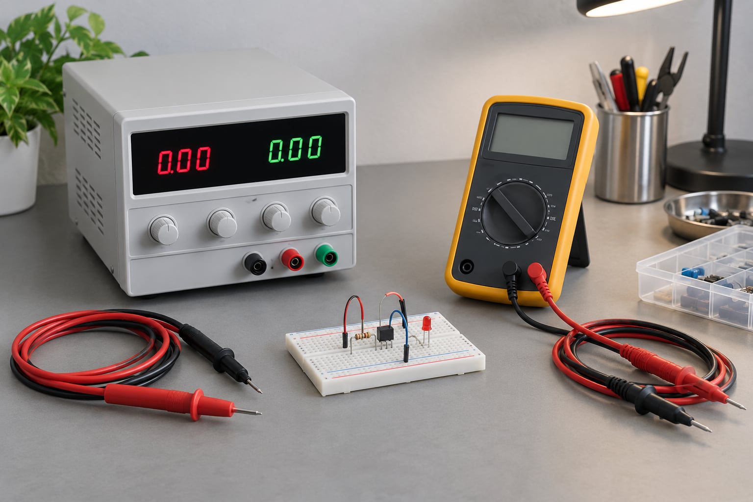
Yes, and that is the classic use. Set the current limit first, a few hundred milliamps for a typical microcontroller project, then connect across the breadboard rails. Keep the current limit set well below what the supply can deliver, because the limit is what protects the components if your wiring is wrong.
Why is my power supply showing a current limit?
Constant-current mode means the load is asking for more current than the ceiling you set, or the output is shorted. Disconnect the load and see whether the indicator clears. If it does, the circuit genuinely needs more current than you allowed. If it does not, the wiring is shorted or the supply has a fault.
Can I connect a bench power supply directly to a battery or motor?
A motor is fine within the voltage and current range, but set the current limit above its running current and above its startup surge, or the surge will trip the limit. A battery is a different matter: putting a bench supply across a cell is not real charging control, since charge termination needs a proper charger with CC and CV stages.
Should the negative terminal of a bench power supply be grounded?
Most supplies tie the negative output terminal to protective earth, which is a safety feature. Some can float it, which helps with ground loops when using a bench scope. Know which one you have, because a scope ground clip connected to a different earth point can short a circuit through the bench earth strap.
How do I measure the output voltage safely?
Set the output below the range you expect, disable the load, and measure with a multimeter across the terminals before connecting anything. Measure at the circuit as well as at the supply, because lead resistance can hide several tenths of a volt at the far end of a breadboard. Confirm polarity before power-up every time.
Where to Start on the Electronics Bench
Take these six steps in order for the first board you power, and every board after it. It takes two minutes and it is the difference between a quick diagnosis and a bag of components.
- Identify what the circuit needs: voltage, current and polarity. Read the schematic or the board markings.
- Verify polarity at the circuit before connecting anything.
- Set the current limit below the expected draw, starting at roughly double what you think the circuit will use.
- Start at zero volts and ramp to the setpoint with the load disconnected.
- Measure the voltage at the circuit with a meter before connecting the load.
- Power down by lowering the limit, then the voltage, then disabling the output, and only then disconnect.
Those six steps cover almost everything a bench power supply does, and they cover it in the order that keeps the circuit alive. Everything else in this guide, from topology to grounding to ripple, exists to help you judge whether the instrument itself is telling you the truth.