In-circuit test and functional test check a printed circuit board for two different things. In-circuit test, or ICT, presses probes onto test points on an unpowered board and measures resistance, capacitance and junction voltage at component level. Functional test, or FCT, powers the assembly up and drives it through simulated real-world conditions to see whether the whole product behaves correctly.
Neither one replaces the other. ICT catches the vast majority of assembly defects, and FCT catches the things a board only misbehaves about when it actually runs. This guide breaks down the difference between the two, then looks at speed, fault coverage, equipment, cost, and how to choose for your production volume.
Table of Contents
- In circuit test vs functional test explained at a glance
- What Is In-Circuit Testing?
- What Is Functional Testing?
- How Do the Test Methods Differ?
- Which Test Method Is Faster?
- Which Test Method Finds More Faults?
- Where the two methods overlap
- What Equipment Does Each Test Require?
- Which Test Is More Cost-Effective?
- Which Should You Choose?
- Frequently Asked Questions
- Is in-circuit testing the same as functional testing?
- What faults does in-circuit testing usually find?
- Does functional testing check individual components?
- Can a circuit board be tested with both methods?
- Which method is better for high-volume manufacturing?
- Why can functional testing produce false failures?
- Conclusion
In circuit test vs functional test explained at a glance
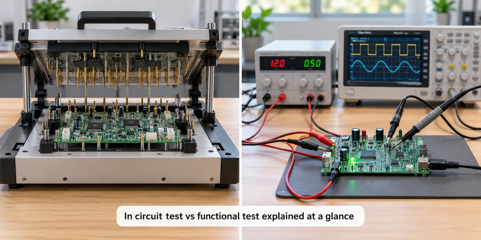
Here is the short version of in circuit test vs functional test explained in one table.
| Criterion | In-Circuit Test (ICT) | Functional Test (FCT) |
|---|---|---|
| Test objective | Confirm every component is present, correct and properly soldered | Confirm the assembled board performs its job |
| Board power state | Unpowered, or powered only at low test currents | Fully powered and running firmware |
| Test access | Bed-of-nails fixture or flying probe on internal nets | External connectors, test points, USB, Ethernet, CAN |
| Typical cycle time | Seconds to tens of seconds per board | Tens of seconds to a few minutes per board |
| Fault coverage | Opens, shorts, wrong values, missing parts, polarity, misaligned parts | Behaviour: firmware, timing, protocols, sensor response, interaction faults |
| Diagnostic detail | Pin-level, points to the exact net or component | Usually a failed function, not a failed component |
| Main setup cost | Custom fixture engineering and programming | Test system, interface modules, fixtures, firmware test software |
| Typical applications | High-volume PCBA production, stable builds | Prototype validation, mixed-signal boards, final system proof |
| Biggest limitation | Needs test access, which dense boards often lack | Gives a vague failure and can produce false failures |
Read that last row carefully. It is the whole argument for running both: ICT is precise but needs access, and FCT needs no access but tells you far less about what went wrong.
What Is In-Circuit Testing?
In-circuit testing measures the electrical condition of individual components and nets while they are still soldered onto the assembled PCB. The board is usually not running any code and often carries no real power. That single design choice makes the measurements stable and repeatable.
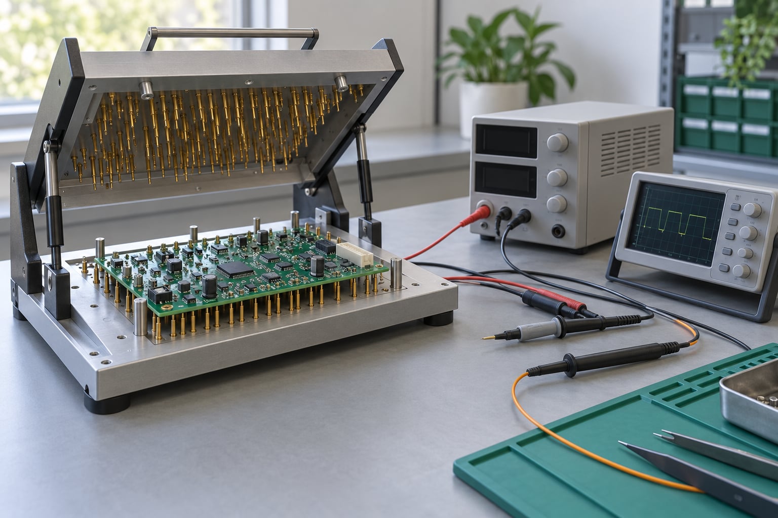
The test head presses spring-loaded pins onto test pads and copper features. A bed-of-nails fixture reaches hundreds of nets in one engagement, which is why it dominates production lines. Flying probe systems move a small number of probes from point to point instead, which suits prototypes and low-volume work where building a fixture does not pay for itself.
The measurements an ICT system typically performs include:
- Continuity and opens to catch a broken trace or a missing connection.
- Shorts between nets that should be isolated, including solder bridges.
- Resistance and tolerance on resistors, to catch wrong values and out-of-spec parts.
- Capacitance on capacitors and, often, on assembled circuits like filters.
- Diode junction voltage, which covers polarity, forward voltage and shorted junctions.
- Component presence on BGA, QFN and other packages that optical inspection cannot resolve.
- Inductor and transformer checks, including DCR on multi-turn windings.
Because each net is measured on its own, fault isolation is very good. A failing net at node 41 on the fixture maps back to a specific component location on the board drawing, so rework does not start with guesswork. Most programs also guard against in-circuit measurement errors caused by parallel paths, applying guarded or four-wire techniques where resistance limits demand it.
One practical limit is access. Fine-pitch BGA parts, dense power sections and RF areas often have no usable probe land. When a board has poor test access, engineers either add pads for a fixture or add boundary scan.
What Is Functional Testing?
Functional circuit testing powers the board, loads its firmware, applies stimulus to its inputs, and measures the responses at its outputs. Instead of asking whether R47 is 4.7 kOhms, FCT asks whether the LED blinks at the right cadence when a button is pressed.
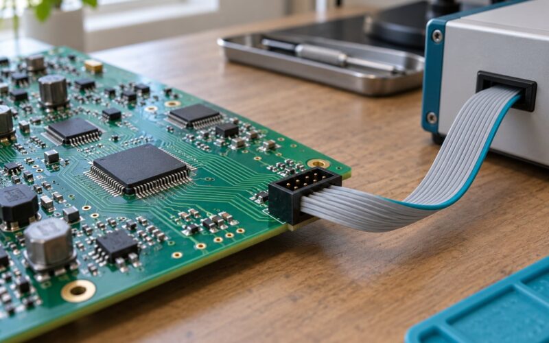
A typical functional station applies power over a range of voltages, drives digital inputs through relay or solid-state matrices, simulates analogue signals with signal generators, and captures outputs on a scope, a data acquisition unit or a protocol analyser. It also talks to the board over USB, Ethernet, CAN, RS-485, UART or a wireless radio.
The work it performs usually includes:
- Power-on verification, checking current draw at several supply rails and watching for rail sequencing problems.
- Firmware loading through ISP, JTAG, SWD or an in-circuit programmer.
- Input simulation on switches, sensors, encoders and analogue channels.
- Output validation on relays, motor drivers, displays, actuators and indicator circuits.
- Protocol and register checks across every interface the product exposes.
- Sensor calibration and compensation, where the product must read known values within tolerance.
- Pairing and RF checks on wireless products, including antenna path losses in the fixture.
This is where a board finally proves it does its job. It is also where non-electrical problems surface: firmware bugs, timing races, wrong register configuration, mismatched part revisions, thermal problems under load, and mismatches between a sensor and its calibration table.
How Do the Test Methods Differ?
The methods differ first in what they can reach. ICT touches nets inside the board. FCT only touches connectors and exposed interfaces, so a defect on a buried trace that never changes the connector behaviour can slip past functional test entirely.
They also differ in diagnostic resolution. An ICT program reports a net name and a measured value. A failing FCT test usually reports a symptom: LED 3 did not light, or the CAN frame timed out. Getting from that symptom to a component is manual work unless the board also has boundary scan.
| Dimension | In-Circuit Test | Functional Test |
|---|---|---|
| Isolation of a single defect | Strong, at net or pin level | Weak, at function level |
| Coverage of assembly defects | Very high | Partial, and only where the defect affects behaviour |
| Coverage of system behaviour | None | High |
| Repeatability between operators | Very high, program-driven | High once the station is proven |
| Risk of a false failure | Low, though parallel paths can mislead | Moderate to high without good fixture design |
| Board handling | Clamped flat in a fixture | Often restrained in a harness or nest |
| Natural production stage | Immediately after soldering and cleaning | After board-level test passes |
Which Test Method Is Faster?
On a running line, ICT is faster. A bed-of-nails fixture engages once and measures thousands of points in seconds, and the board never has to boot anything. Flying probe is slower per board, often tens of seconds, because the probes move mechanically, but it still beats a full functional sequence on a stable design.
FCT costs more time for reasons that are not obvious until you run one. The station has to apply power and let rails settle, wait for firmware to boot, run a scripted sequence, and often allow retries. A board that passes takes that whole path.
The real time sink is failure. When a board fails functional test, an operator has to reproduce the symptom, probe around it and often reload firmware. That debugging session can run many times longer than the original test. This is why good programs treat ICT as the fast filter that keeps ambiguous failures out of the slower station.
Which Test Method Finds More Faults?
ICT finds more faults overall, and it finds nearly all of the ones that come from manufacturing. Missing parts, tombstoned small passives, cold joints on power rails, micro-shorts, wrong polarity diodes, misaligned BGAs and unpopulated optional circuits are all visible to an electrical measurement and invisible to a functional test that merely observes the product not working.
There is a specific set of failures only FCT reaches:
- Firmware that boots but configures a peripheral incorrectly.
- Timing problems that only appear when the real workload runs.
- Protocol errors under realistic message traffic.
- Sensor reads that are present but out of calibration range.
- Signal integrity and crosstalk problems that appear only at speed.
- Thermal behaviour under sustained load.
- Interaction faults across subsystems, where each part works alone.
Where the two methods overlap
Coverage is not additive. Both methods can flag a bad power rail, and both will catch a shorted output. The overlap is where a combined strategy earns its keep: ICT acts as a precise screen, FCT acts as the final acceptance gate. Boards that pass both have been checked at net level and then at system level, and the failure data from each stage is different enough to be worth having.
What Equipment Does Each Test Require?
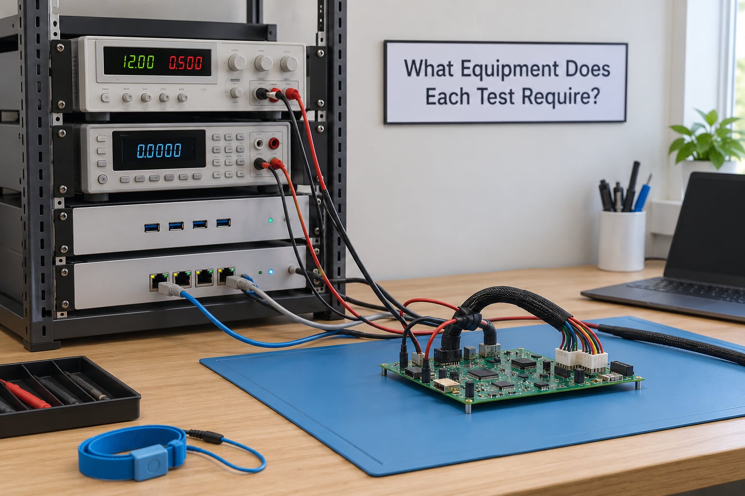
An ICT station needs a test head with measurement hardware for resistance, capacitance, inductance and diode function, plus a fixture built for the specific board. Fixtures come in several actuation styles. Clamshell units close a lid onto the board, vertical fixtures press straight down through a platen, and vacuum or pneumatic actuation holds the board flat with lower pin force, which matters on fragile or large-format assemblies. Probe pitch options run from 100 mil down toward 15 mil for fine work, with beryllium copper pins in gold-plated tips on production fixtures.
Flying probe systems trade coverage for flexibility. They need no custom fixture, which is why they turn up on prototypes and pilot runs, but probing is slower and coverage is lower because every net needs its own approach.
A functional station needs a bench supply or programmable supply, relays or solid-state switch matrices for input simulation, data acquisition, protocol interfaces for USB, Ethernet, CAN or RS-485, scope and multimeter access, and often an environmental enclosure if the product is temperature sensitive. Test software on top ties it together, and fixture design decides how many false failures you will chase.
Two supporting tools matter enough to plan for. Boundary scan, accessed over JTAG, lets a system drive a pattern into an FPGA or ASIC and observe the pins around an inaccessible cluster, which is how boards without probe lands still get structural test coverage. Second, test software and a golden-unit strategy: keeping a known-good board on hand to compare against when the station produces an unexpected result saves more time than most people expect.
Signal integrity in the fixture is a real constraint that grows with frequency. Long parallel wires and harness runs in a functional station act as antennas and transmission lines, so designers keep leads short, use twisted pairs where they can, add shield or ferrites on sensitive lines, and measure how far the harness has degraded a signal before blaming the board.
Which Test Is More Cost-Effective?
Neither method is cheaper in the abstract. ICT puts most of its cost up front: custom fixture engineering, probe pin sets, test program development and a test head. That spending pays back only across volume. A bed-of-nails fixture for a stable production part commonly runs into five figures in fixture cost and takes weeks to build, so it is hard to justify on a handful of prototypes.
FCT shifts the cost to per unit. The station hardware is often shared, and the fixture is simpler, but every board still pays in operator time, cycle time and software development. Development is also slower to start, because a functional test is only as good as the firmware on it and the stimulus behind each step.
Three costs are easy to overlook when teams compare the methods:
- Rework and scrap. Catching a defect on a bare board before it is populated is dramatically cheaper than debugging a finished assembly, which is the main argument for putting ICT early in the flow.
- Escape cost. A defect that reaches the customer costs more than everything else combined, and this is where functional coverage earns its keep.
- False failures. A flaky functional station destroys throughput and erodes trust in the line, so fixture and station design deserve budget.
As a rule of thumb, higher volume and a more stable design push you toward ICT. Lower volume, frequent design changes and heavy firmware content push you toward FCT. Mixed-signal products with real analog behaviour usually need FCT even at volume.
Which Should You Choose?
Pick the method by looking at your worst defect class first, not by which machine is cheaper to buy.
- High-volume production of a stable board with good probe access: ICT first. It is fast, repeatable and carries most of the assembly defect load.
- Prototypes and new product introduction where the design changes weekly: flying probe plus a light functional smoke test. Building a fixture before the design freezes is wasted money.
- Mixed-signal boards with analog front ends, RF sections or sensors that need calibration: FCT is the only way to verify the behaviour that customers pay for.
- Complex digital systems with firmware, processors or FPGAs: FCT, and usually boundary scan as well, because ICT says nothing about code.
- Automotive, medical, aerospace and industrial control boards where traceability and defect evidence matter: both, sequenced, with records from each stage.
- Dense boards with no practical test access: add boundary scan during design so structural coverage survives without a bed-of-nails fixture.
When you run both, the order is standard. Step one, ICT immediately after soldering and cleaning, while the board is still bare of any enclosure and easy to handle. Step two, retest after any repair, using the same program so the fix is verified against the original failure. Step three, FCT as the final gate, with the board in its normal operating configuration. Step four, record both results against the serial number, because the pair together is your evidence of workmanship.
That sequence works because each stage filters for the next. Boards arriving at FCT are far more likely to fail for a real design reason, so the functional station stays useful instead of becoming a debugging desk.
Frequently Asked Questions
Is in-circuit testing the same as functional testing?
No. In-circuit test measures component values and net conditions on an unpowered board to find assembly defects. Functional test powers the assembly and drives it through simulated real conditions to see whether the product performs correctly. One checks construction, the other checks behaviour.
What faults does in-circuit testing usually find?
ICT typically finds opens, shorts between nets, wrong resistor or capacitor values, reversed polarity, missing components, misaligned BGA and QFN parts, cold joints and micro-shorts. These are manufacturing defects that a functional test only sees indirectly, usually as a product that fails to start.
Does functional testing check individual components?
Not directly. Functional test works at the interface level, applying stimulus to inputs and measuring responses at outputs. It will reveal a failed regulator or dead amplifier, but it does not measure the component itself. That level of detail comes from in-circuit test or boundary scan.
Can a circuit board be tested with both methods?
Yes, and most production lines that build complex assemblies do exactly that. ICT runs first, right after soldering, to screen out assembly defects. Functional test runs last as the final acceptance gate. Running them in sequence keeps boards reaching the slower station as clean as possible.
Which method is better for high-volume manufacturing?
ICT, when the board is stable and has usable test access. Fixture cost is high, but it is amortised across the run and cycle times are measured in seconds, so it handles volume well. High-mix or frequently revised products still need functional coverage even at high volume.
Why can functional testing produce false failures?
The board is only one variable in a functional station. Long harness wiring, poor grounding, an unstable power supply, incorrect stimulus timing, an unprogrammed device or a marginal component can all fail a board that is actually good. Good fixture design and a proven golden unit keep the false-failure rate down.
Conclusion
Start by naming the failure that would hurt you most. If it is a soldering or assembly defect slipping to the customer, put in-circuit test early, with a bed-of-nails fixture for volume or flying probe for prototypes. If it is firmware, timing, signal integrity or system interaction, functional test is the only thing that will show it.
For most assembled products the answer is both, in sequence: ICT as the fast, precise screen, FCT as the final proof that the product does its job. Fix test access early in the design with probe pads and boundary scan, because retrofitting either one after a board is in production is expensive.