A battery management system (BMS) is the electronic controller that sits between a rechargeable battery pack and the charger or load it serves. It measures every cell’s voltage, the pack current and the temperature, then decides whether the pack may safely keep operating. This guide walks through the hardware, the control loop and the chemistry-specific limits that define one.
The BMS is not the battery and it is not the charger. It is the safety and control layer that makes a multi-cell pack usable, and understanding it means understanding which measurements a pack actually needs and what the controller does with them.
Below is battery management systems explained block by block, from the sensing chain through to the protection decisions the controller makes.
Table of Contents
- What Is a Battery Management System?
- Why Batteries Need Management
- Battery Management Systems Explained by Core Components
- How Does a Battery Management System Work?
- How Does a Battery Management System Estimate State of Charge?
- Open-circuit voltage lookup
- Coulomb counting
- Model-based estimation
- How Does Cell Balancing Improve Capacity and Safety?
- Passive balancing
- Active balancing
- What Protections Does a Battery Management System Provide?
- Battery Management Systems Explained by Chemistry and Cell Voltage Limits
- How Does a BMS Communicate With Chargers and Loads?
- What Are the Main BMS Design Trade-Offs?
- What Design Practices Make a BMS More Reliable?
- Frequently Asked Questions
- Does every rechargeable battery need a battery management system?
- Is a battery management system the same as the battery charger?
- What is the difference between passive and active cell balancing?
- Why does a battery pack have less usable capacity than the sum of its cells?
- Can a battery management system prevent a battery from overheating?
- What happens if the battery management system fails?
- Conclusion
What Is a Battery Management System?
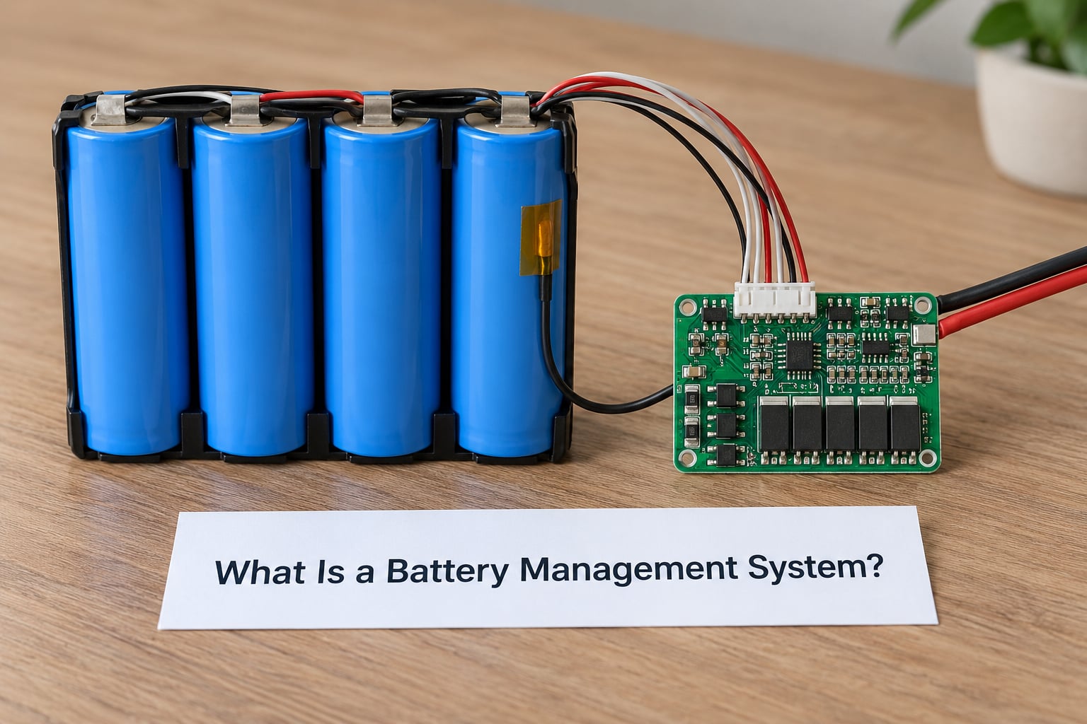
A battery management system is the electronic brain of a rechargeable battery pack: it monitors every cell’s voltage along with pack current and temperature, protects the pack from damage by disconnecting it when a limit is exceeded, balances cells so they wear at the same rate, and estimates how much charge and how much useful life remain. That estimation is usually reported as state of charge, state of health and state of power.
The word pack matters here. A single 18650 cell needs almost no management. Four cells wired in series need far more, because the string’s capacity and its voltage window are set entirely by the weakest cell in it.
So the BMS is not the charger. A charger supplies current according to a charge profile. The BMS measures the pack and decides whether that charger is allowed to keep working, at what current, and when to stop.
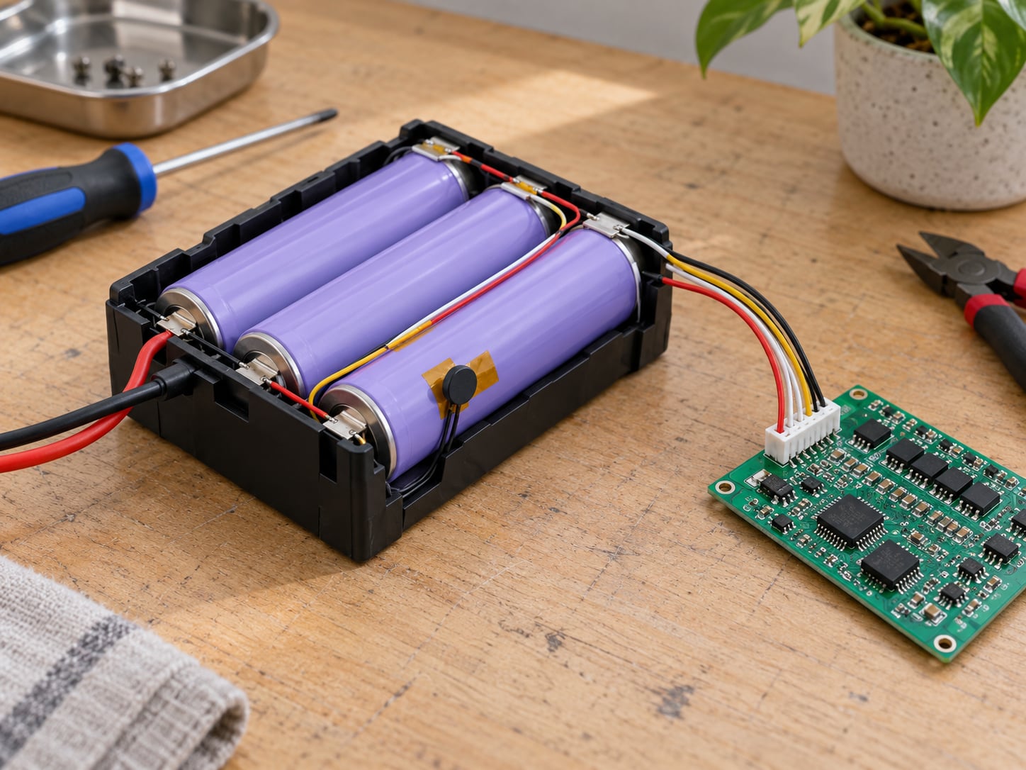
It is also not the pack itself. The pack holds the cells, busbars, insulation and enclosure. The BMS is the board with the sensing, analog front end, microcontroller and switching elements that interfaces to it.
Why Batteries Need Management
Every failure mode below is a reason a battery management system exists. Left ungoverned, any one of them can shorten a pack’s life or start a fire.
- Overcharge: pushing a cell above its maximum voltage drives parasitic reactions, gasses the cell and damages the SEI layer. On a lithium-ion cell this is the fast route to thermal runaway.
- Over-discharge: a cell driven too low gains a permanent internal copper dissolution damage and its capacity does not come back. In a series string one weak cell drags the whole pack down.
- Excessive current: current above the cell’s rating raises internal heating. Peak current matters, but so does the C-rate averaged over time.
- Voltage imbalance: cells differ in capacity, internal resistance and self-discharge from the factory. A series string must stay inside the window of its weakest cell, so imbalance directly reduces usable capacity.
- Heat: temperature is the strongest single accelerator of degradation. Charging a cold cell fast, or any cell above roughly 45 C, accelerates side reactions and lithium plating.
- Aging: every cycle adds loss of lithium inventory and loss of active material. A BMS limits the operating envelope so aging happens slowly rather than abruptly.
None of this is visible from the outside. A pack looks identical whether it is balanced or not, so the measurements have to be taken continuously rather than checked occasionally.
Battery Management Systems Explained by Core Components
Every battery management system is the same seven blocks arranged differently. Knowing which block sits between the failure and the response is most of the debugging work.
| Component | Input | Function | Typical failure concern |
|---|---|---|---|
| Cell taps | Voltage at each cell node | Bring every cell in a series string to a measurement point | Open or high-resistance tap produces phantom imbalance |
| Analog front end | Differential cell voltages | Multiplex and measure each cell to microvolt accuracy | Reference drift and channel crosstalk corrupt the whole image |
| Shunt resistor | Pack current | Generate a small voltage proportional to current | Drift or heating changes the current reading over time |
| NTC thermistors | Temperature | Track cell, module and coolant temperature | Slow response and self-heating bias the reading |
| Balancing network | Cell voltage deltas | Transfer charge off high cells or into low ones | FET stuck on bleeds a cell continuously |
| Contactor or MOSFET bank | Control decision | Connect or isolate the pack from the load and charger | Welded contacts defeat every software protection |
| Microcontroller | All measurements and limits | Estimate state, run protection logic, drive outputs, log faults | Firmware bug or watchdog failure can hold outputs in the wrong state |
Low-voltage parts usually run off the pack’s own supply through a linear regulator, which means the controller must wake from near-zero current and manage its own brownout behaviour.
Isolation is the other structural decision. In a high-voltage pack the measurement circuitry floats hundreds of volts above the vehicle chassis, so digital isolators and a communication isolator sit between the low-voltage domain and everything touching the cells.
How Does a Battery Management System Work?
The whole system runs one loop over and over: sense, filter, estimate, decide, actuate, report. Each step below repeats continuously while the pack is active.
- Wake-up and self-test. The microcontroller powers up, checks its supply rails, verifies the analog front end reference and confirms that the cell tap wiring and thermistor resistances are plausible. A failed self-test usually blocks the main contactors from closing.
- Measurement. The analog front end multiplexes every cell voltage in sequence, then the shunt and the thermistors are read. Cell taps are measured in parallel with the balancing network switched off, otherwise bleed current shows up as measurement error.
- Filtering. Raw readings are noisy because current switching injects transients. The firmware applies averaging, rejects samples taken during a transition, and checks the reading against the expected cell count.
- Estimation. The controller computes state of charge, state of health and available power from those measurements plus its internal model and its stored history.
- Safety checks. Every cell voltage, the pack current and every temperature are compared against programmed limits. Fault flags are latched with a timestamp so a transient event is not lost.
- Balancing. If the spread between the highest and lowest cell exceeds the threshold, balancing is enabled for the affected cells and only during conditions where it is safe.
- Charge and discharge control. The controller sets the permitted current window, blocks charge outside the temperature window, and lets the charger know when absorption and termination are allowed to begin.
- Actuation. On a fault the main contactors or MOSFET bank open, isolating the pack. On a healthy pack they stay closed and the system reports over the bus.
- Shutdown. When the pack is idle the controller drops to a low quiescent current, waking periodically to check for a charger or load before re-enabling balancing.
That last point explains a lot of forum confusion: a healthy BMS can look dead because it is in sleep and simply waiting to be woken by a charger connection.
How Does a Battery Management System Estimate State of Charge?
State of charge (SoC) is the percentage of rated capacity currently stored, and it is the number drivers and apps actually see. Three methods are used, usually in combination.
Open-circuit voltage lookup
A rested cell’s voltage maps to a charge level through a chemistry-specific curve. This is accurate at low current when the cell has settled, and inaccurate under load because of the internal resistance drop and the polarization that comes with it.
Coulomb counting
The controller integrates measured current over time and subtracts from the previous estimate. It tracks well between full charges but drifts whenever the current reading is even slightly wrong, and it has no idea what the starting state was unless the pack was recently at a known voltage.
Model-based estimation
An equivalent circuit model describes the cell as a voltage source plus series resistance and one or more RC branches, and a filter such as a Kalman filter or extended Kalman filter corrects the coulomb count using the voltage residual. Better models add temperature dependence, hysteresis and an ageing term.
Temperature and ageing are what break naive lookups. A cold cell and a hot cell at the same voltage hold different charge, and an aged cell’s open-circuit voltage curve shifts. Current error matters just as much: a small bias in the shunt integrates into a large SoC error over days.
Related estimates sit alongside SoC. State of health (SoH) expresses remaining capacity and internal resistance relative to a new pack, usually as a percentage. State of power (SoP) is the power the pack can deliver or accept right now, which depends on both SoC and temperature.
How Does Cell Balancing Improve Capacity and Safety?
A series string is limited by its weakest cell. If one cell reaches the maximum voltage first, charging stops even though the other cells still have room, so imbalance costs usable capacity on every cycle.
Cells drift apart for ordinary reasons: manufacturing tolerance in capacity, differing internal resistance, differing self-discharge rates, and temperature gradients across the pack. DIY builders see this constantly, where a pack of nominally identical cells settles within a couple of millivolts after balancing but can show a much larger spread before it.
Passive balancing
Passive balancing connects a resistor across any cell whose voltage is above the lowest cell in the string. The resistor wastes that energy as heat and slowly pulls the high cell down toward the others.
- The controller measures every cell.
- Cells above the target threshold are selected.
- A resistor is switched in parallel with each selected cell.
- Balancing stops once the delta falls below the threshold or the pack leaves the balancing state of charge window.
Active balancing
Active balancing transfers charge from the high cells into the low cells through a converter instead of burning it. Balance currents of a few amps are practical in a vehicle pack, which closes large deltas far faster than a resistor network.
| Factor | Passive balancing | Active balancing |
|---|---|---|
| Mechanism | Resistor bleeds charge off high cells | Converter moves charge from high cells to low cells |
| Balance current | Typically tens to a few hundred milliamps | Typically amps |
| Efficiency effect | Energy is dissipated as heat | Energy is largely recovered |
| Hardware complexity | Low, one FET and resistor per cell | High, bidirectional converter and inductors |
| Where it fits | Small packs, power tools, e-bikes, consumer devices | EV packs and stationary storage where capacity matters |
A worked example makes the cost of imbalance concrete. Consider a 4S pack of nominal 3.7 V cells with 100 Ah each, giving 400 Ah at the pack level. If one cell sits 100 mV below the others and the upper cells hit the 4.2 V limit first, the usable capacity is set by that low cell rather than by the nameplate.
Parallel strings deserve a separate note. Cells in parallel share current naturally, so balancing is less critical, but each parallel group still needs to start at the same state of charge or the strings will fight each other, which is why pre-balancing cells to a common voltage before assembly matters.
What Protections Does a Battery Management System Provide?
Protection is layered on purpose. Software limits shape normal behaviour; hardware mechanisms stop the pack when software cannot.
- Overvoltage protection: a cell above the maximum cell voltage blocks further charge, and above a higher hard limit the contactors open.
- Undervoltage protection: a cell below the cut-off voltage blocks discharge. Many packs also lock out and require a charger to wake them, which is a safety feature and a common source of user confusion.
- Overcurrent protection: sustained current above the limit triggers a timed shutdown; a short circuit triggers an immediate one.
- Short-circuit protection: a fast comparator on the shunt voltage, or a pyrotechnic or fuse-based device in high-voltage packs, disconnects in milliseconds.
- Over-temperature protection: charging is blocked outside roughly 0 to 45 C, and discharge is restricted at the extremes.
- Reverse-polarity and insulation monitoring: miswired packs and insulation faults are detected and reported rather than left to fail silently.
Fail-safe behaviour is the design question underneath all of these. If sensing fails, the controller should treat the pack as unsafe. If communications fail, the pack should shut down rather than run open-loop. If the controller itself stops executing, the watchdog resets it and the outputs revert to their safe state.
Battery Management Systems Explained by Chemistry and Cell Voltage Limits
Cell voltage, cell resistance and chemistry-specific charge behaviour determine most BMS parameter choices. A controller designed for one chemistry is not simply usable on another.
| Chemistry | Nominal cell voltage | Full charge | BMS implications |
|---|---|---|---|
| Lithium-ion NMC / NCA | About 3.6 to 3.7 V | About 4.2 V | Narrow voltage window, active balancing common, SoC needs a model because the OCV curve is flat mid-range |
| Lithium iron phosphate (LiFePO4) | 3.2 V | 3.65 V | Flat OCV plateau, so OCV lookup works well; higher cell count for the same pack voltage |
| Lead-acid | 2.0 V | 2.4 V | Bulk and absorption charge with temperature compensation; balancing less critical because cells self-correct on float |
| Nickel-metal hydride | 1.2 V | About 1.45 V | Charge termination by temperature rise and voltage plateau, so the controller watches thermistors closely |
| Flow battery | About 1.3 to 1.5 V | Varies by chemistry | State of charge follows tank levels and concentration rather than cell voltage; balancing is largely unnecessary |
LiFePO4 deserves one caution. Its flat voltage plateau between roughly 20 and 80 percent makes voltage-based SoC estimation poor in that range, and its cell count for a 48 V pack is much higher than NMC, which multiplies the number of measurement channels the analog front end must handle.
How Does a BMS Communicate With Chargers and Loads?
The BMS publishes measurements and permissions, and receives instructions. The bus choice is mostly about distance, node count, isolation and cost.
- CAN: the default in vehicles and industrial equipment, robust against noise and fast enough for safety-relevant messages.
- RS-485: long cable runs in stationary storage and solar inverters, with good noise immunity over distance.
- UART: simple point-to-point links between a cell monitoring unit and a master controller inside a pack.
- SMBus and I2C: low-speed links to fuel gauges, EEPROMs and sensors on small consumer packs.
- Discrete signals: charge and discharge enable lines, a pre-charge request and a fault relay, which is all a basic tool pack needs.
A typical message path runs from the pack to the charger, which asks whether charge is permitted and at what current, then to the vehicle or device controller, which uses the same data to manage power limits, and finally to service diagnostics, which reads logged fault codes.
Isolation sits on the wire whenever the pack floats at high voltage. A fault on a CAN line in a 400 V pack must not become a path to ground, so galvanic isolation and a defined fault state are part of the interface design, not add-ons.
What Are the Main BMS Design Trade-Offs?
Most BMS compromises come from the same handful of quantities. Improving any one of them usually costs something else.
- Measurement accuracy versus cost: tighter cell-voltage accuracy needs a better reference, more filtering time and more careful layout.
- Balance current versus quiescent current: a larger balance network discharges faster and also consumes more standby power, which matters in a sleeping pack.
- Response time versus noise rejection: averaging cleans up readings but slows reaction to a genuine fault.
- Cost versus redundancy: duplicated sensing channels and redundant contactors raise cost but are often mandated in automotive work.
- Isolation versus data integrity: more isolation stages protect people but add delay and error sources.
- Diagnostics versus firmware complexity: richer logging helps the field but grows the attack surface and the validation burden.
- Cyber security versus connectivity: any remote access path, including a service port, needs authentication and update control.
| Application | Dominant constraint | Architecture that fits |
|---|---|---|
| Consumer electronics and power tools | Cost and board area | Single IC with integrated protection and a fuel gauge |
| Electric vehicles | Functional safety and thousands of cells | Distributed cell monitoring units under a master BMS, redundant contactors |
| Stationary storage | Long life, thermal margin and grid compliance | Modular monitoring with active balancing and a supervisory energy management layer |
One boundary is worth stating plainly: the BMS manages the pack, while the energy management system above it manages the system. In a battery energy storage system, the EMS decides how the pack is dispatched against price signals and grid commands, and the power conversion system does the actual current conversion.
What Design Practices Make a BMS More Reliable?
Reliability comes from margins and verification rather than from clever algorithms alone. In practice these habits show up repeatedly.
- Calibrate at end of line. Store the offset and gain of every measurement channel in memory at manufacture. Voltage measurement accuracy that drifts over a cell’s life is a common root cause of phantom imbalance.
- Design for tolerance, not for nominal. Cell taps, thermistor placement and shunt layout should tolerate component spread and connector variation, because those vary across production lots.
- Keep protection margins. Set software limits a little inside the cell’s rated limits, and put a hardware cut-off outside the software limit.
- Make the watchdog meaningful. On a watchdog reset, outputs must default to the safe state rather than to whatever they last held.
- Recover cleanly from brownout. Test what happens when supply voltage dips mid-operation, and make sure a recovered controller does not re-enable the pack before it has re-read every measurement.
- Handle the thermal path. Thermistors sit close to cells, and the balancing components need to dissipate without becoming the heat source they are measuring.
- Test the failure modes on purpose. Inject open taps, shorted thermistors, shunt drift and stuck balancing FETs during design validation, not just nominal operation.
When something does go wrong, the log is the starting point. A fault code with a timestamp, the cell voltage snapshot at that moment and the current reading narrow the cause far faster than guessing at the symptom.
Frequently Asked Questions
Does every rechargeable battery need a battery management system?
Multi-cell packs need one. A pack with two or more cells in series has no other way to know whether a single cell is over- or under-charged, because the string voltage hides individual cell behaviour. Single-cell packs usually still carry a protection circuit, either a discrete chip or a protection board built into the cell. Packs with cells in parallel only need balancing for comfort rather than safety, since parallel cells share current.
Is a battery management system the same as the battery charger?
No, they do different jobs. The charger supplies current following a charge profile such as bulk, absorption and float, and it usually acts as if the pack is healthy. The battery management system measures the pack and decides whether charging or discharging is permitted at all, at what current, and when the pack must be isolated. Many designs also let the charger ask the BMS for a charge limit.
What is the difference between passive and active cell balancing?
Passive balancing connects a resistor across any cell sitting above the lowest cell in the string, bleeding energy away as heat. Balance currents are typically tens to a few hundred milliamps. Active balancing uses a converter to move charge from high cells into low cells at amps of current, recovering most of the energy. Passive is simpler and cheaper; active closes large deltas faster and is used in vehicle packs.
Why does a battery pack have less usable capacity than the sum of its cells?
Because a series string can only use the energy its weakest cell allows. Charging stops when the highest cell reaches its maximum voltage, and discharging stops when the lowest cell reaches its cut-off. Nameplate capacity is measured with every cell sitting at the same voltage, so any imbalance reduces what you actually get. Balancing exists to close that gap over time.
Can a battery management system prevent a battery from overheating?
It reduces the risk, but it does not make overheating impossible. A BMS blocks charge and restricts current outside safe temperature windows, which removes the main causes of heat such as high C-rate charging, over-discharge and imbalance. It cannot remove the heat generated by a hard short circuit or an external fire, and a passive pack with no temperature sensing has no way to react at all.
What happens if the battery management system fails?
How it fails depends on the design, and safe designs are built around the worst case. A stuck output or welded contactor is the dangerous failure, because protection is defeated and the pack is isolated by nothing. Well-designed systems treat missing measurements or lost communication as faults and open the pack rather than running open-loop. A controller that stops executing should reset through its watchdog and return outputs to the safe state.
Conclusion
A dependable battery management system combines five things: accurate measurement of every cell, chemistry-aware control, active or passive balancing, layered protection with a defined safe state, and communications that tell the rest of the system what the pack can safely do. Remove any one of them and a pack becomes either unsafe or short-lived.
Before specifying a controller, write down five numbers and one behaviour. The cell chemistry, the pack series count and voltage window, the continuous and peak current, the ambient temperature range, and the required safety reaction to each fault. The design then follows from those, rather than from a datasheet picked first.
There is a practical reason to want battery management systems explained at the block level: that is where failures are actually diagnosable, and where the line separates a pack that works for a season from one that works for a decade.