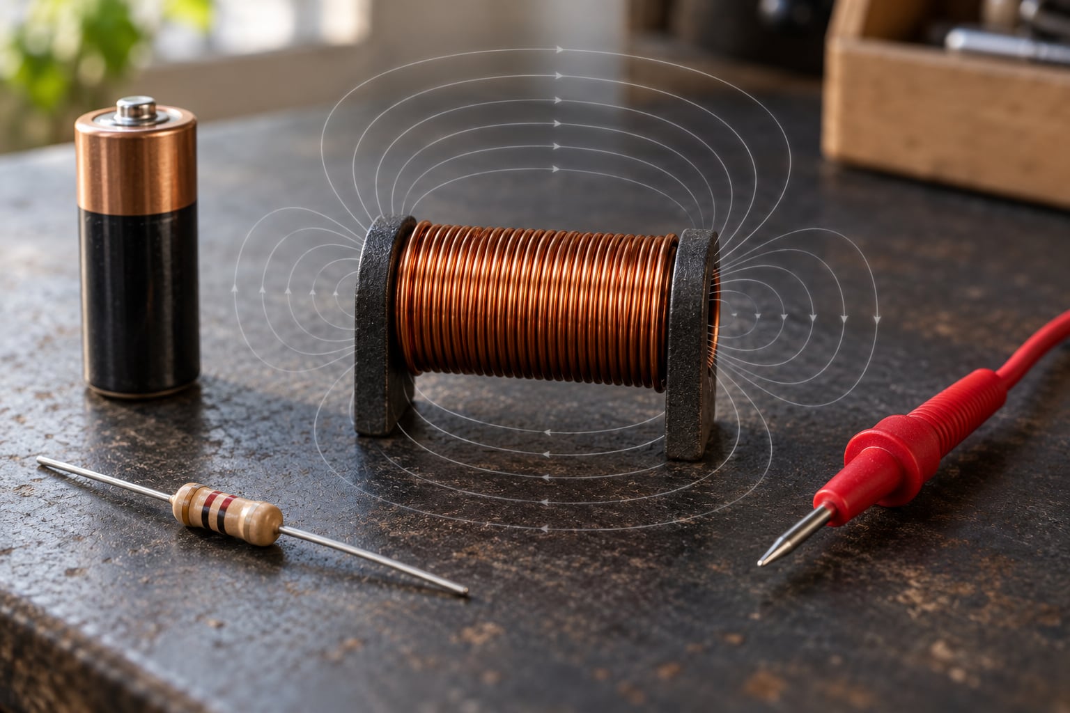
An inductor is a passive component, usually a coil of wire wound around a core, that stores energy in a magnetic field and opposes any change in the current flowing through it. That single sentence covers most of what a beginner needs: the coil stores, and the coil resists change. Updated for 2026.
The rest of this guide unpacks that idea. We will look at what happens inside the coil, what the numbers on a datasheet mean, and how to pick a sensible part for a circuit you actually want to build.
Table of Contents
- What Is an Inductor?
- How an Inductor Stores and Releases Energy
- Inductor Basics for Electronics Beginners: Key Terms
- What Is Inductance?
- What Is Inductor Tolerance and Current Rating?
- How Inductors Behave in DC and AC Circuits
- Common Uses for Inductors
- How to Choose an Inductor for a Beginner Circuit
- Inductor Basics: A Simple Worked Example
- Common Beginner Mistakes
- Frequently Asked Questions
- Can you explain an inductor in a simple way?
- Does an inductor allow AC or DC?
- What are the three types of inductors?
- How can I make my own inductor at home?
- What is DCR on an inductor datasheet and why does it matter?
- Should I use a discrete inductor or a ferrite bead?
- Conclusion
What Is an Inductor?
Definition: An inductor is a two-terminal passive component built from a conductor wound into a coil, usually around a magnetic core. Current passing through it builds a magnetic field and stores energy; that field also works against any change in current, which is why you will see inductors described as coils, chokes or reactors depending on who is writing the datasheet.
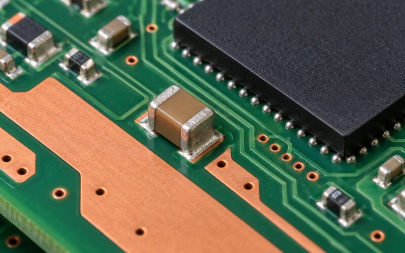
Physically, most inductors are a wire wound many times around ferrite, iron, powdered iron, or in the simplest case nothing at all. Some are wound on a bobbin and potted in epoxy, and the small surface-mount parts on a circuit board are the same idea shrunk down. A relay or a loudspeaker voice coil is also an inductor in the physical sense, though you would not order it from a passive component catalogue.
One naming habit trips up newcomers. An inductor is the component, inductance is the property it has, and a choke is an inductor deliberately used to block a frequency rather than to store energy for a converter. Some datasheets from TDK, Murata or Coilcraft use the terms loosely, so read the inductance and current rating rather than trusting the label. A transformer is a different component: it has two windings that pass energy from one to the other through the shared field.
How an Inductor Stores and Releases Energy
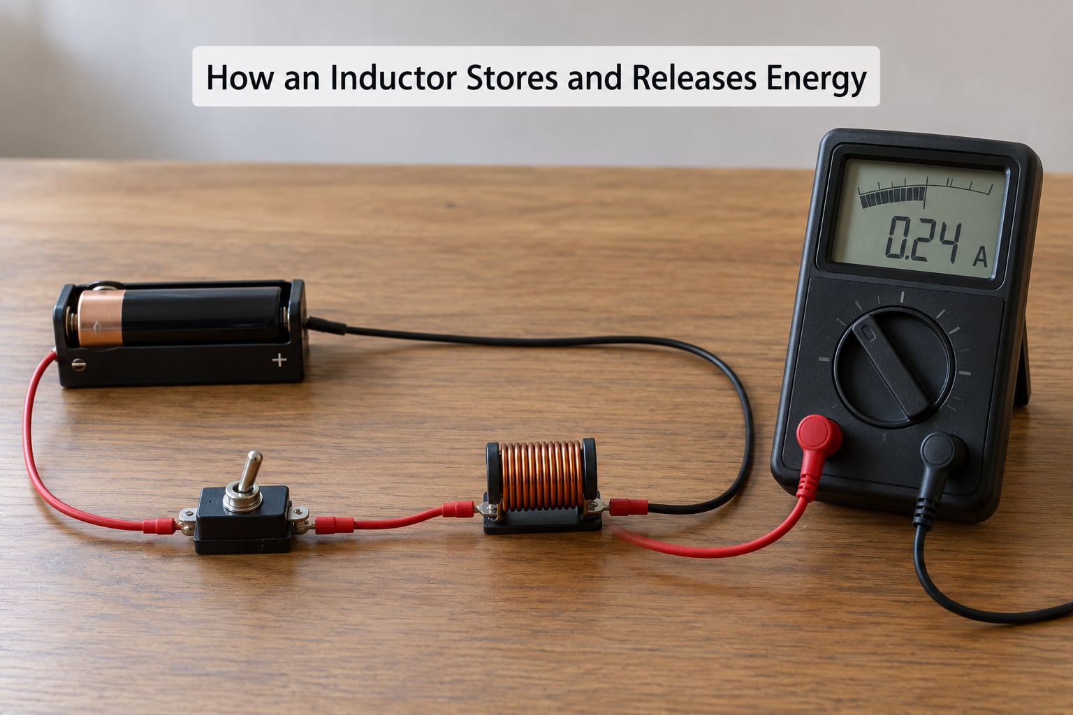
Current flowing through a coil produces a magnetic field around it. The Right Hand Rule gives you the direction: curl your fingers around the coil in the direction of current and your thumb points along the field through the core. That field is the stored energy, and it grows as current grows.
Here is the part that confuses most first-time builders. When the current changes, the changing magnetic field induces a voltage across the coil that pushes back against the change. Faraday found that a changing magnetic field makes a voltage; Lenz worked out that the induced voltage always opposes the change causing it. Combine them and you get the rule that defines an inductor: it resists change in current, not current itself.
So switch the current on and the inductor fights the ramp, turning the energy you supplied partly into a magnetic field instead of letting the current jump instantly. Cut the supply while the switch is open and the field collapses, and the collapsing field produces a voltage in the same direction as the old current. The coil keeps the circuit powered briefly on its own, which is exactly how a relay driver or a boost converter coasts through a switching gap.
Energy in a magnetic field grows with the square of current, and a bigger core or more turns gives you more energy for the same current. Both are worth remembering when you size a part, because the inductor in a power supply is usually chosen for how much energy it must hold between two switching events, not just for its inductance number.
Inductor Basics for Electronics Beginners: Key Terms
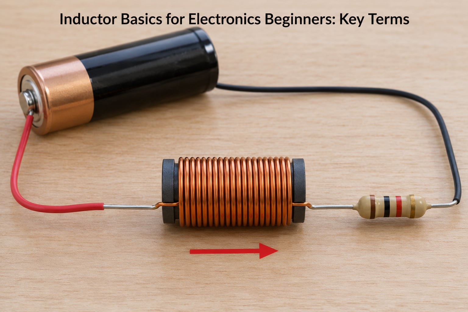
Getting fluent in inductor basics for electronics beginners mostly means getting fluent in a handful of terms that keep appearing on datasheets. Here they are in plain language, and they are the same words I use for the rest of this guide.
| Term | Symbol | What it means for you |
|---|---|---|
| Inductance | L | How much the coil resists a change in current, measured in henry (H). 10 microhenry is a small signal part; 10 millihenry is a power supply part. |
| Henry | H | The unit of inductance. 1 H, 1 mH (millihenry) and 1 microH are the same unit at different scales. |
| Inductive reactance | XL | The opposition an inductor offers to alternating current. It grows with frequency: XL = 2 pi f L. |
| Impedance | Z | Total opposition to AC. For a real inductor it combines reactance with the winding’s resistance. |
| DC resistance | DCR | The resistance of the wire itself. On DC this is the only opposition the inductor offers, and it is usually small. |
| Saturation current | Isat | The current at which the core runs out of magnetic capacity. Past this point inductance collapses and the part gets hot. |
| Self-resonant frequency | SRF | The frequency where the coil’s own stray capacitance resonates with it. Above SRF it stops behaving like an inductor. |
| Mutual inductance | M | How much energy one winding passes to a second coil through the shared field. This is the transformer effect. |
Two of those deserve extra emphasis for a beginner. DC resistance is the one that decides whether your 5 V rail really sees 5 V, because the current has to get through the winding’s own resistance. Saturation current is the one that decides whether the inductor survives a load step, because inductance that collapses under load changes the whole converter.
Self-resonant frequency is the one people skip and then regret. Every coil has capacitance between its turns, and once the signal reaches SRF the pair resonates and the impedance stops climbing with frequency. Inductor basics for electronics beginners gets a lot easier once you accept that an inductor is only an inductor below its self-resonant frequency.
What Is Inductance?
Inductance is the measured property of a coil: how many henries it takes to generate one volt of back EMF for a given rate of current change. One henry means one volt of induced voltage per ampere per second, which is why the unit is called after the physicist who put it in order.
For a simple solenoid, the relationship between geometry and inductance is:
L = N squared x mu x A / l
Read it in words. N is the number of turns, and inductance rises with the square of it, so doubling the turns gives roughly four times the inductance. mu is the core permeability, which is why an iron or ferrite core beats an air core of the same size. A is the cross-sectional area of the core, and l is the mean length of the magnetic path. You can see the N squared term is the dominant one for hand-wound coils.
A worked example makes it concrete. Take 20 turns of wire around a core 10 mm across and 20 mm long, with no core material at all. The core area is about 7.85 x 10^-5 square metres, the path length is 0.02 m, and air permeability is 1.2566 x 10^-6. That gives roughly 2 microhenry. Put the same 20 turns on a ferrite core with a relative permeability of 100 and you would expect about 200 microhenry instead, though at higher frequency the core losses eat into that gain and the saturation limit arrives much sooner.
That comparison is also the practical rule for hand-wound work: turns are cheap and square-law, core material is the multiplier, and once you need real energy at low frequency you are shopping for a core size rather than a winding.
What Is Inductor Tolerance and Current Rating?
An inductor datasheet rarely gives you one number. It gives a nominal inductance plus a tolerance band, a current rating, a saturation current, a DCR figure and a self-resonant frequency, and each of those changes how the part behaves in your circuit.
| Specification | What it tells you | What goes wrong if you ignore it |
|---|---|---|
| Nominal inductance and tolerance | The L value and how far the real part may sit from it, commonly plus or minus 20 percent for general parts and plus or minus 5 percent or tighter for precision lines | Your filter corner or converter ripple lands somewhere other than the frequency you calculated |
| Rated current | The continuous DC current the part is specified to carry without exceeding its temperature rise rating | The winding overheats in a closed enclosure, even though nothing is technically broken |
| Saturation current | The DC current where inductance starts falling away sharply | Instant collapse of inductance, huge ripple current, damaged switching device |
| DC resistance | The voltage drop and heat generated by the winding itself | Output sag under load, or a supply that never quite reaches its target voltage |
| Self-resonant frequency | The upper limit of useful inductive behaviour | A filter that passes noise instead of removing it, or an RF tank that will not tune |
Tolerance is the least dangerous of these, because an inductor is rarely used where a few percent matters. Filter corners and converter inductors tolerate wide bands happily. Saturation current and DCR are the two that decide whether a board works on the bench and then fails in the enclosure.
Rated current and saturation current are also not the same number. Rated current is a thermal limit for steady DC. Saturation current is a magnetic limit, and it is usually lower, which is why a datasheet lists both and why the inductor in a switching converter is checked against peak current with margin rather than against average current.
How Inductors Behave in DC and AC Circuits
Does an inductor allow AC or DC? Both, but it treats them very differently. On steady DC the magnetic field stops changing once the current settles, so the back EMF disappears and the inductor behaves like nothing more than its winding resistance, which is a few milliohms for a typical power inductor. On AC the field is constantly changing, the back EMF never stops, and the inductor presents a real opposition called inductive reactance, XL = 2 pi f L.
The practical consequence is that impedance against AC climbs with frequency while it stays flat against DC. That single property is why one component can smooth the output of a buck converter and, in a different circuit, block a 5 MHz interference signal while passing a 100 Hz one.
The other beginner surprise is time. Add a resistor to an inductor and the current cannot jump; it ramps toward the supply voltage along an exponential curve with a time constant of tau = L / R. Take L = 10 millihenry and R = 100 ohms, and tau works out to 100 microseconds. After one time constant the current has reached about 63 percent of its final value, after five it is within 1 percent, and that half millisecond of ramp is exactly the delay a relay driver or a solenoid depends on.
Disconnect the supply with the same 10 millihenry inductor and the stored field drives the current down through zero and out the other way, decaying along the same kind of curve. If you put a diode across the coil, that negative swing has somewhere safe to go, which is the standard flyback protection on a relay or a motor.
Common Uses for Inductors
Once you know that an inductor stores energy and blocks fast changes, the applications stop looking like a list and start looking like one idea reused.
- Switching power supplies. The inductor in a buck or boost converter smooths the chopped input current between switching cycles. Pick the inductance for the ripple current you will tolerate and the saturation current for the peak, or the converter will get hot and loud.
- DC-DC converters and battery regulators. The same trick at a different voltage level, often with a shielded inductor to keep the magnetic field off nearby circuits.
- EMI filtering and common-mode chokes. Noise on a cable or a switching node wants to escape through the ground plane. A choke in the path blocks that, and a two-winding common-mode choke handles the pair of conductors that noise rides on together.
- LC low-pass filters. Pair an inductor with a capacitor in front of a load and together they pass low frequencies and attenuate high ones. This is how a rail or an audio signal gets cleaned up before it reaches the next stage.
- Oscillators. A Hartley or Colpitts oscillator needs a resonant tank, which is exactly an inductor and a capacitor trading energy back and forth. Without the inductor there is no way to get a phase shift and start sustained oscillation.
- RF matching and signal integrity. Matching networks use an inductor to cancel the capacitive part of a load so a transmitter or antenna network sees a clean resistive value. Above a few megahertz, SRF and core losses decide which parts you can actually use.
- Audio crossovers. A small air-core inductor with a capacitor forms the low-pass leg of a speaker crossover, while a larger inductor handles the low-pass side of a woofer or a motor choke on an amplifier.
- Relay, solenoid and motor drivers. The coil is an inductor with a moving part attached. Drive it with a transistor plus a flyback diode so the collapsing field does not destroy the transistor.
How to Choose an Inductor for a Beginner Circuit
Work through these in order and most of the guesswork disappears.
- Set the inductance from the circuit, not from stock. A filter corner, an RL time constant or a converter ripple target all give you a number to calculate from. Round to the nearest standard value afterwards.
- Check the frequency against SRF. If the inductor runs above its self-resonant frequency, it is a resonator, not an inductor. Pick a larger part or a different family.
- Check average current against the rated current. Work out your RMS current, add a margin of roughly 30 to 50 percent, and remember that a part running near its limit in free air may run hot in a sealed box.
- Check peak current against the saturation current. This is the number that kills parts. Compare the worst-case peak, not the nominal load.
- Look at DCR and work out the loss. Losses are roughly I squared x DCR. A 50 milliohm inductor carrying 1 A dissipates about 50 milliwatts, which is trivial; the same part at 4 A dissipates 800 milliwatts and will tell you about it.
- Decide on shielded or unshielded. Shielded parts confine the field and help with EMI, at a small inductance penalty. Unshielded parts give you slightly higher inductance and lower DCR for the size, but the field escapes and can disturb nearby circuits.
- Match the package and the core. Through-hole parts are easier to hand solder and easy to swap. Ferrite cores suit tens of kilohertz to a few megahertz, powdered iron and silicon steel handle lower switching frequencies with higher current, and air core suits RF where you do not want a core at all.
- Read the markings before you power the board. Through-hole parts often use a colour code or a printed value. Surface-mount parts usually print the value directly, sometimes with a three-digit code where the first two digits are significant and the third is a multiplier in microhenries, so 102 means 1.0 microhenry and 472 means 4.7 microhenry.
You can also make your own, which is genuinely useful for learning and occasionally for a one-off RF or audio circuit. Wind insulated wire around a former or a ferrite rod, keep the turns tight and even, and count them. More turns and a shorter coil give more inductance; spread the turns out to reduce stray capacitance. Then measure it, because the arithmetic only ever gets you close. An LCR meter is the easy answer, and if you do not have one, a cheap capacitance-to-inductance or LC meter adapter plugged into a multimeter gives you a usable reading within a few percent for a hobby bench.
Inductor Basics: A Simple Worked Example
Say you want to convert 5 V down to 3.3 V at up to 1 A with a buck converter switching at 500 kHz, and you have decided 0.2 A of ripple current is acceptable.
The duty cycle works out at 3.3 divided by 5, or 0.66, which leaves 0.34 of the cycle for the inductor to charge. Ripple current in a buck is the output voltage times one minus the duty cycle, divided by inductance times switching frequency. Solving for inductance gives L = 3.3 x 0.34 / (0.2 x 500000), which is about 11 microhenry. A 10 microhenry part puts you close; a 15 microhenry part sits a little under your ripple target, so pick whichever matches your standard values.
Now the parts of that choice the inductance number never told you. Peak current is your 1 A load plus half the ripple, so about 1.1 A, and you want a saturation current rated comfortably above that, ideally 1.3 A or more. At 1 A with a typical 50 milliohm DCR the inductor wastes about 50 milliwatts, which is fine. SRF for a 10 microhenry power inductor usually sits well above 500 kHz, but check it anyway since that is the whole point of reading the datasheet.
None of those checks needs the full simulation toolchain. They need the datasheet, the ripple target and a sense of which failure you are trying to avoid. Simulation becomes worth it once you are chasing efficiency numbers or layout-dependent behaviour, not at this stage.
Common Beginner Mistakes
- Choosing on inductance alone. A 10 microhenry part exists in hundreds of forms. Current rating, saturation, DCR and SRF are what make one of them right.
- Treating the inductor as the DC load limit. It is not a fuse or a ballast resistor. On DC it is a short with a few milliohms of wire resistance, and the real limit is thermal.
- Assuming ideal behaviour at high frequency. Above SRF the stray capacitance takes over and the impedance stops rising. This is why switching nodes and RF nets need different parts entirely.
- Using an inductor with plenty of rated current but too little saturation current. Rated current is a heat number. Saturation current is the one that decides whether inductance collapses when the load steps up.
- Ignoring DCR in a low-voltage supply. A short inductor in a 1.2 V rail is a significant fraction of your available voltage.
- Wiring polarity into a part that has none. A moulded or shielded RF inductor is non-polarized. A diode, an electrolytic capacitor or a polarised inductor is not, and reversing a polarised part is how you get a very short-lived board.
- Forgetting layout. An inductor near a sensitive signal trace will couple into it, which is why power inductors in switching designs are shielded or placed deliberately away from sensitive nodes.
- Skipping the reverse diode on a relay or solenoid. The coil’s collapsing field spikes the supply node, and without somewhere for that energy to go you find out how much it takes to destroy your transistor.
Frequently Asked Questions
Can you explain an inductor in a simple way?
An inductor is a coil of wire, usually wound around a core, that stores energy in a magnetic field and opposes any change in the current through it. Current flowing through the coil builds a field, and a changing field induces a back voltage that fights the change. That is why an inductor passes steady DC but resists fast switching and rising frequencies.
Does an inductor allow AC or DC?
Both, but the behaviour is completely different. On steady DC the magnetic field stops changing, so the inductor offers only its winding’s DC resistance, usually a few milliohms. On AC the changing field creates a continuous back voltage, giving an inductive reactance of X-L = 2 pi f L that grows with frequency. High frequency sees high opposition; DC sees almost none.
What are the three types of inductors?
Beginners usually meet three families. Fixed inductors come in through-hole or surface-mount packages with a set inductance, chosen for current handling and DC resistance. Adjustable inductors have a movable ferrite slug or threaded core so you can tune the value in circuit. Chokes, including common-mode chokes, are wound specifically to block unwanted high-frequency noise on a supply line or a cable.
How can I make my own inductor at home?
Wind a few turns of insulated wire around a small ferrite rod, a pencil, or a spool of a chosen diameter. Keep the turns tight, even and in the same direction, and count them. More turns and a shorter coil give more inductance; spreading them out reduces stray capacitance. Leave long tails to connect in circuit, then measure the value with an LCR meter or an LC meter adapter, since the calculation will not be exact.
What is DCR on an inductor datasheet and why does it matter?
DCR is the DC resistance of the winding itself, measured in milliohms. It is the only opposition an inductor gives to steady DC current, and it turns into heat at roughly I squared times DCR. On a low-voltage rail that drop matters: a 50 milliohm part carrying 1 A loses 50 millivolts and 50 milliwatts. Higher DCR also means a larger, warmer, usually more expensive part.
Should I use a discrete inductor or a ferrite bead?
A ferrite bead is a very small inductor, typically around 100 ohms of impedance at 100 MHz, used to choke high-frequency noise on a line. Choose a bead when you only need HF suppression on a signal or supply trace and current is modest. Choose a real inductor when you need a defined inductance value, meaningful stored energy, higher current, or a lower frequency response than a bead provides.
Conclusion
Inductor basics for electronics beginners come down to one idea: a coil stores energy in a magnetic field, and that field pushes back against any change in current. Everything else follows from it. The rest is learning to read the datasheet, starting with saturation current and DC resistance, and checking the frequency against the self-resonant point.
If you want one place to start, build the 10 millihenry and 100 ohm RL circuit with a switch and a multimeter. Watching the current climb slowly instead of jumping instantly is the fastest way to make the physics stick.