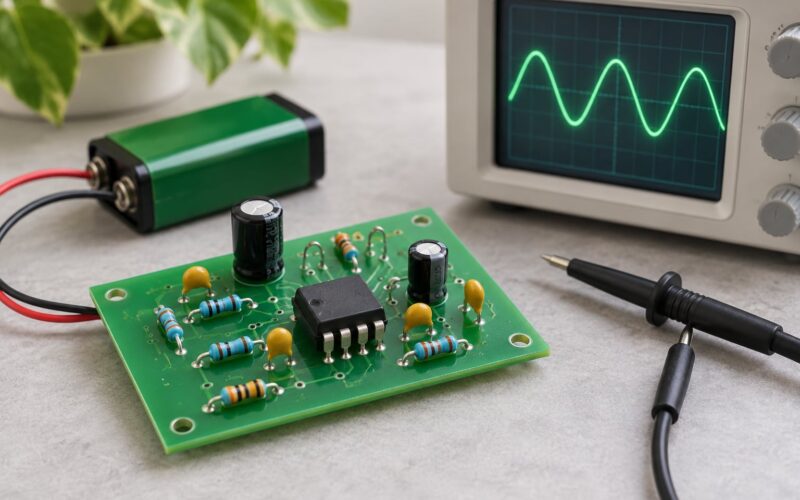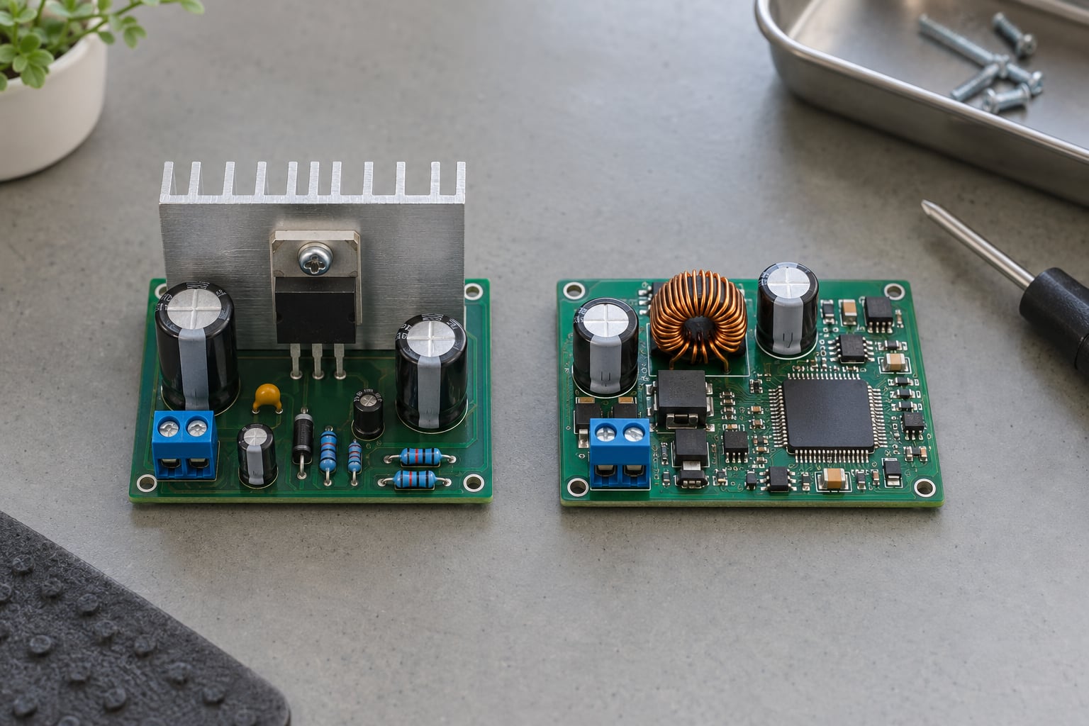
Voltage regulator types compared across the four things that decide a design: efficiency, output noise, how hard the part is to implement, and the current it can deliver. A linear regulator or LDO wins when the input sits close to the output and a quiet rail matters. A switching regulator — buck, boost or buck-boost — wins whenever there is a meaningful voltage difference to convert or the load current climbs into amps. There is no single best type; there is the right one for a given input, output, load and noise budget.
One thing worth clearing up before the comparison. When people search this term they sometimes mean AC power equipment: single-phase versus three-phase stabilisers, servo voltage regulators, static regulators and ferroresonant units that sit on mains feeds. Those are a completely different family of devices from the DC and IC-level regulators covered here, and nothing below applies to them. If you are sizing equipment for a factory or household supply, search on servo and ferroresonant instead.
The rest of this guide is aimed at the people who actually pick the silicon: hardware engineers, PCB designers, chip architects and embedded developers building a board that needs a stable rail from a noisy or varying source, as of 2026.
Table of Contents
- Voltage Regulator Types Compared at a Glance
- What are the three main types of voltage regulators?
- Linear Voltage Regulators: Simple and Low Noise
- Low-Dropout Regulators: Linear Regulation with a Small Voltage Headroom
- Buck Regulators: Efficient Step-Down Voltage Conversion
- Boost Regulators: Raising Voltage Efficiently
- Buck-Boost Regulators: Handling Rising and Falling Voltages
- Integrated PMICs: Multiple Rails in One Package
- How to Compare Efficiency, Noise, Ripple, and Transient Response
- Efficiency versus input voltage and load
- Output noise and ripple
- Transient response and loop stability
- Thermal limits and measurement expectations
- Which Voltage Regulator Type Should You Choose?
- Frequently Asked Questions
- Are LDOs and linear regulators the same thing?
- Which voltage regulator type is most efficient?
- Why does my regulator get hot?
- How do I choose between a buck regulator and an LDO?
Voltage Regulator Types Compared at a Glance
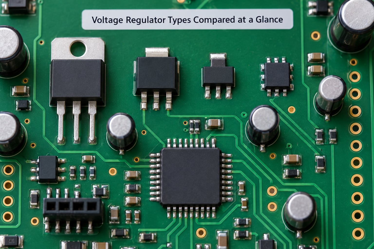
| Regulator type | Topology | Typical efficiency | Output noise | Input vs output voltage | Design complexity | Current capability | Relative cost | Best applications |
|---|---|---|---|---|---|---|---|---|
| Linear (series pass) | Series pass transistor or MOSFET, no switching | Approximates Vout/Vin | Very low, no switching ripple | Output must be below input | Lowest; input/output caps and a pass device | Low to medium, commonly tens of mA to a few amps | Low | Simple fixed rails, hot standby rails, post-regulation cleanup |
| Low-dropout (LDO) | Linear series pass with a small dropout spec | Approximates Vout/Vin, better at small headroom | Very low | Output just below input | Low; output capacitor stability is the main trap | Low to medium | Low to medium | Sensor rails, RF and audio, low-noise analog, 3.3V MCU rails off a 3.6V cell |
| Buck (step-down) | Switching inductor with a high-side switch | Often 85 to 95 percent | Contains switching ripple at fsw | Output well below input | Medium to high; inductor, input and output caps, feedback divider, loop compensation | High; amps to tens of amps | Medium | 3.3V and 5V rails from 12V or 24V, processors, battery power paths |
| Boost (step-up) | Switching inductor with a low-side switch | Often 85 to 95 percent | Contains switching ripple at fsw | Output above input | Medium to high, same component set as a buck | Medium | Medium | LED drivers, battery to 5V adapters, driving higher gate or bias rails |
| Buck-boost (four-switch) | Two inductors, four switches, inversion and inversion of the output | Often 90 percent or better across the range | Contains switching ripple at fsw | Output above or below input | Highest; two inductors, more switching states | Medium | Medium to high | Single-cell battery systems, USB power paths, variable inputs |
| Integrated PMIC | Multiple converters plus control, sequencing and monitoring in one package | Combines switching efficiency with LDO-grade outputs | Mixed; LDO outputs are quiet | Depends on the rails inside | High at the system level, low at the board level | Per-rail; usually medium | Medium | SoCs and processors needing several sequenced rails from one supply |
What are the three main types of voltage regulators?
Three families cover almost every design. Linear regulators, including low-dropout types, pass current through a series element and burn the excess voltage as heat, so they are quiet and simple. Switching regulators chop the input into pulses and filter them through an inductor and a capacitor, which makes them far more efficient. Integrated power management ICs package several converters, linear outputs and control logic into one part when a board needs multiple rails.
One extra category sits alongside those: shunt regulators, which dump excess current into a load path rather than passing it through a series element. They are simple and short-circuit tolerant but waste power by design, so they show up in voltage references and low-current monitoring rather than on power rails.
Linear Voltage Regulators: Simple and Low Noise
A linear voltage regulator uses a series pass element — a bipolar transistor, a MOSFET or a tube in very old designs — to hold the output at a fixed value while a feedback loop senses the error and drives the pass device harder or softer. The output ends up cleaner than the input because the pass element filters, and the whole thing is a handful of parts: the pass device, a reference, a feedback divider, and input and output capacitors.
The cost of that simplicity is arithmetic you can do in your head. Power out equals output voltage times load current; power in equals input voltage times the same current. Efficiency is simply Vout divided by Vin, and everything left over becomes heat in the pass device. Take a 12V input feeding a 5V rail at 1A: the output is 5W, the input draws 12W, and the regulator has to dissipate 7W in a package you probably chose for 1W. That is a 42 percent efficient regulator heating up fast enough to matter.
That single ratio explains almost every linear versus switching decision. At 5V in and 3.3V out the same regulator is 66 percent efficient, which is usually acceptable. At 5V in and 4.9V out it is 98 percent, and the argument for a switching part evaporates. The closer the output sits to the input, the less there is to lose, which is why linear regulators keep showing up in designs that people assume are switching-only.
Linear parts also do things switching parts do not. Output noise is genuinely low, there is no switching frequency to bleed into nearby circuits, transient response is fast because there is no inductor to slew, and the control loop is simple enough to be stable across wide temperature without compensation work. The failure modes are equally clear: heat, limited input-to-output ratios, and quiescent current that matters in battery designs.
Low-Dropout Regulators: Linear Regulation with a Small Voltage Headroom
An LDO is a linear regulator designed to work when the input is only slightly higher than the output, typically within a few hundred millivolts, so you keep a working rail right down to the battery’s last volts instead of cutting out early.
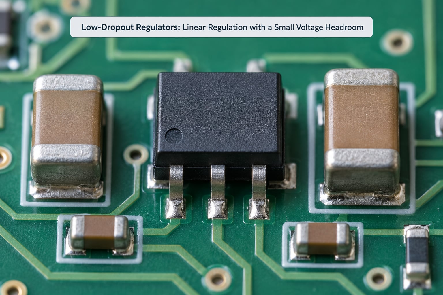
Dropout voltage is the difference between the lowest input that still regulates and the nominal output. A classic LM7805 needs roughly 2V of headroom; a modern LDO can be specified at 20 to 200mV, and some precision parts go lower. Dropout is not a free parameter: it is set by how the internal pass MOSFET is biased and by the part’s ability to drive the gate at low input voltages, so pushing dropout lower usually costs quiescent current or output impedance.
Two specifications decide whether a given LDO fits. Output current capability covers the load plus the divider current, and a regulator that folds back into current limit or drops out under a transient will show up as a brownout on your microcontroller. Quiescent current is the draw from the input when the output is not delivering anything, and on a coin cell it can be the difference between a device that lasts a year and one that lasts a month.
Stability is the part that catches people out. Almost every LDO needs an output capacitor, and many modern parts are only stable with a specific ESR range, which rules out some very low-ESR ceramic combinations. The datasheet capacitance and ESR curves are not boilerplate, and using the wrong capacitor is the most common reason an otherwise clean rail starts ringing.
The forum consensus, which matches the arithmetic, is simple: if the output sits close to the input and noise matters, use an LDO; if the output is far below the input, use a buck. The crossover point is where Vout divided by Vin falls below the efficiency of a well-designed switching regulator at your actual load, and above that headroom a buck wins on power, below it the LDO often wins outright. It is also common to see a buck feeding an LDO — post-regulation — where the buck handles the big voltage difference efficiently and the LDO strips the switching ripple off the rail feeding analog or RF circuitry.
Buck Regulators: Efficient Step-Down Voltage Conversion
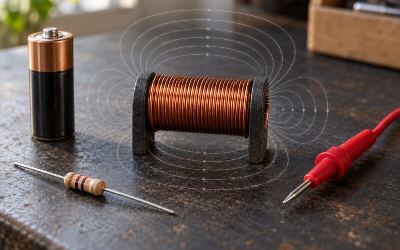
A buck converter takes a higher input voltage and produces a lower regulated output by repeatedly switching current into an inductor, storing energy in the inductor’s magnetic field, then releasing it through a capacitor into the load. The inductor smooths the pulses and the capacitor removes what is left, so the output is DC again.
Efficiency comes from the fact that energy is moved in slugs rather than burned. Parts rated for small and mid power typically land somewhere in the 85 to 95 percent range once you account for switching losses, conduction losses, and the quiescent draw of the control circuitry. Where a linear regulator’s efficiency was fixed by the voltage ratio, a buck’s efficiency varies with load, and light-load behaviour is where a lot of parts lose ground: a converter drawing 1.5mA of quiescent current looks poor on a 10mA load even though its datasheet peak efficiency is impressive.
Understanding conduction mode explains most of the datasheet curves. In continuous conduction mode the inductor current never falls to zero, the part behaves predictably, and efficiency is at its best. In discontinuous conduction mode, at light loads, the current falls to zero between switching cycles, and both switching and conduction losses per delivered watt climb. Most modern controllers use pulse-skip or diode-emulation modes to soften the light-load region, which is worth checking if battery life is the goal.
Because the control loop is actively switching, a buck also introduces a frequency, an inductor, and a feedback network, and it rewards good layout. The switching node at the top of the inductor is noisy and should be kept as small as possible and away from sensitive traces; the input capacitor needs a very low ESR ceramic right at the device; the feedback divider should tap the output capacitor rather than the pin to keep the loop short. Synchronous rectification, where a second MOSFET replaces the freewolding diode and cuts its conduction loss, is standard in anything modern. A common entry point part is the LM2596 for simple adjustable designs, with parts like the TPS5430 serving fixed-rail, higher-current applications.
Boost Regulators: Raising Voltage Efficiently
A boost converter does the opposite of a buck: it takes a lower input and produces a higher output, again by switching current into an inductor and then rectifying that stored energy onto the output. The basic component set is identical to a buck, only the switch and diode swap positions relative to the inductor and the output node.
Two characteristics define the design envelope. First, the output cannot be lower than the input unless you add a disconnect path, because the inductor dumps current through the diode straight into the output whenever the switch is off. If a load could back-drive the output, that diode forward-biases and you can get a run-away boost. Second, the achievable ratio is limited: pushing a 3.7V cell to 24V means large boost ratios, which demand careful inductor and capacitor selection and make ripple and regulation harder to control than a straightforward step-down.
Output voltage ceiling is set by the switch and diode voltage ratings plus the part’s own limit, so a converter rated to 28V out cannot be pushed to 30V no matter how the inductor is chosen. Boost converters also radiate more than people expect, because the switch node swings the full output voltage every cycle; keeping that loop area small and watching the ground return matters for anything with an antenna or a microphone nearby.
Typical targets are LED drivers, where a constant-current loop is often added on top of the voltage loop, and battery-to-5V adapters for single-cell devices, which is the job parts like the MT3608 are usually bought for. They also show up driving gate drive or bias rails where the source supply is too low to reach the required level.
Buck-Boost Regulators: Handling Rising and Falling Voltages
A buck-boost converter produces a regulated output that can be either above or below its input, which is exactly what you need when the source swings across the target — a single Li-ion cell discharging from 4.2V to 3.0V while you need 3.3V, for example.
The older inverting buck-boost topology drives the inductor so the output is the inverse of the switch node. That gives an output at the opposite polarity from the input, or a negative output when the input is positive, so a negative rail comes out of a positive supply with no extra level shifting. It is efficient and simple, but the inverted output means any load referencing that rail has to tolerate ground being somewhere unusual, which is why inverting parts often end up inside a PMIC or paired with a charge pump rather than used bare on a hobby board.
The four-switch buck-boost avoids the polarity problem by using two inductors and four switches. One inductor steps the input down to an intermediate node, the other steps that node up, and the controller picks the direction so the output always lands above the input when it needs to and below when it does not. Because the output stays in phase with the input, a negative regulator and a battery charger can coexist in the same converter — which is why the architecture shows up in USB-C power path designs and in the parts hobbyists reach for, such as the LTC3780.
The trade is complexity. Two inductors mean more board area and more parts to select, four switches mean more switching states to compensate for, and the control loop has to hand off between directions without the output dipping. If your input is reliably above or reliably below the target, a plain buck or boost is the better engineering choice.
Integrated PMICs: Multiple Rails in One Package
An integrated power management IC combines several converters, low-dropout outputs, and the control logic around them — sequencing, enable, current monitoring, voltage tracking, thermal shutdown, and sometimes a charge pump — into a single package. A processor-based board that needs core, I/O, memory and a housekeeping rail would otherwise need four separate regulators and the glue logic to bring them up in a defined order.
What you gain is board area, part count, and control. Sequencing matters more than people expect: a microcontroller is rarely happy to see its I/O rail come up before its core rail, and a PMIC handles that with a small register write rather than discrete delay circuits. A good PMIC also exposes telemetry — current, temperature, fault flags — over I2C or a similar bus, which turns a rail fault from something you debug with a scope into something the firmware can see.
What you give up is flexibility. The rails are fixed or limited to a set the vendor programmed, and the thermal situation is often worse than discrete parts because the converters share a package and share a copper area. If the output needs to be 7.3V at 1.5A, no PMIC is the answer. Many modern parts also trade the analog feedback loop for a digital or hybrid control mode, which gives excellent behaviour and telemetry but removes the ability to tweak compensation on the bench — worth knowing if you are the kind of engineer who reaches for a scope and a potentiometer.
How to Compare Efficiency, Noise, Ripple, and Transient Response
Efficiency, noise, transient response and heat are where the choice is actually made. Here is how to weigh each one against your own rail rather than a datasheet headline.
Efficiency versus input voltage and load
For a linear regulator, efficiency is Vout divided by Vin, so it is fixed by your voltage ratio and gets worse as the headroom grows. For a switching regulator, efficiency is a curve: it peaks at a mid load, falls at very light loads because of quiescent current, and falls again at very heavy loads because of conduction and switching losses. Plot your actual load range against the curve, not the peak number, and include the loss of adding an LDO after the buck.
Output noise and ripple
Linear regulators are quiet by nature. Switching regulators put energy at the switching frequency on the output, plus a wideband component, and you manage it with capacitor selection, an LC filter stage, and careful placement of the switching loop. Post-regulation — a buck feeding an LDO — is the standard technique when a rail feeds audio, RF, a sensor amplifier or anything with an ADC on it, because the LDO rejects the switching ripple while the buck absorbs the voltage drop. Power supply rejection ratio, quoted in dB versus frequency, is the number that tells you how much of the input disturbance ends up on the output.
Transient response and loop stability
Step the load and watch the output. Linear parts respond almost immediately, which is why a droop on a heavy load step is often an LDO’s current limit rather than its loop. Switching regulators have an inductor in the loop, so the response is set by the compensation network and the output capacitor’s capacitance and ESR. A marginally stable design shows up as ringing on the output, growing oscillation with added load, or a slow recovery after a step — all of which can be fixed with different compensation values rather than a different topology.
Thermal limits and measurement expectations
Compute dissipation before you pick a package, not after the board is populated. For a linear regulator it is (Vin minus Vout) times Iout, so a 5V to 3.3V conversion at 500mA puts 0.85W into the part. Then check junction temperature rise against the thermal resistance of the package and the copper area you gave it, because the same die in a small footprint on a small board can hit limits that a datasheet with a generous test board never shows. For switching regulators, efficiency curves published at a specific input, output and temperature are the honest measurement, and thermal design still matters for the controller and the inductor.
If you want to see the difference yourself, probe the output at the load with a short ground spring rather than a long clip lead, and look at both the ripple at the switching frequency and the low-frequency droop. Measurement mistakes here are common enough that engineers on electronics forums almost always start by asking what probe and where.
Which Voltage Regulator Type Should You Choose?
Match the type to the rail rather than to the trend. Here is the short version, case by case.
- Low-drop clean rail for analog or RF: an LDO, fed either from a clean supply or post-regulating a buck if the switching ripple matters.
- Battery-powered system where the cell sits just above the rail: an LDO with a specified low dropout and low quiescent current. This is the case where the arithmetic favours the linear part.
- High-current processor rail from 12V or 24V: a synchronous buck, sized on thermal dissipation and transient response, with the datasheet compensation values copied exactly.
- Raising a voltage, such as an LED string or a 5V output from one cell: a boost, with the switch node kept away from sensitive nodes and the output ceiling checked against the part’s rating.
- Negative supply, or a supply that may be either polarity: an inverting buck-boost, or a charge pump if current is low and you can live with its output impedance.
- Variable input that crosses the output value: a four-switch buck-boost, accepting the extra complexity for one regulator that works over the whole range.
- Several sequenced rails for a processor or SoC: an integrated PMIC, if its rails match your system.
The decision checklist, in order: write down your minimum, nominal and maximum input; write down your output and the current at the worst case; calculate linear dissipation as (Vin minus Vout) times Iout and see whether the package survives it; if the headroom is large and the current is more than a few hundred milliamps, plan a buck; if the rail feeds sensitive analog, plan post-regulation; check quiescent current against your battery budget; and only then choose a part.
Frequently Asked Questions
Are LDOs and linear regulators the same thing?
An LDO is a type of linear regulator, so the terms are not interchangeable in every context. A linear regulator is the family: a series pass element with feedback, of which the classic LM7805 is one example. An LDO is a linear regulator engineered for a small dropout voltage, often under 300mV, so it keeps regulating when the input is only slightly above the output. Using the two terms as exact synonyms is what leads people to expect 2V of headroom from a part that actually needs 100mV.
Which voltage regulator type is most efficient?
Buck, boost and buck-boost switching regulators are usually the most efficient when there is a substantial voltage difference to convert, commonly reaching 85 to 95 percent. Efficiency is not a fixed property, though: it peaks at a mid load and drops at light load because of quiescent current. A linear regulator’s efficiency is fixed at Vout divided by Vin, which is why an LDO converting 5V to 4.9V is more efficient than almost any switching part.
Why does my regulator get hot?
A linear regulator dissipates roughly the load current multiplied by the voltage it is not using, so 12V to 5V at 1A wastes 7W in the package. Excessive input voltage, high load current, too little copper area, missing thermal vias, and an undersized package all make it worse. Check the calculation before assuming a fault: if the arithmetic already exceeds the part’s thermal rating, the answer is a switching converter or a bigger package, not more airflow.
How do I choose between a buck regulator and an LDO?
Choose a buck when efficiency, battery life, current capability or a large voltage difference is the priority, and choose an LDO when the input is only slightly above the required output and low noise matters. A useful crossover is to compare Vout divided by Vin against the buck’s efficiency at your actual load. If the linear ratio is close to or better than the buck’s, the LDO wins on both efficiency and noise.
Start with the arithmetic, not the part number. Calculate the linear dissipation for your actual worst case, and if that number is uncomfortable, the comparison has already told you which way to go: switching for the big voltage difference, linear for the small one, and an LDO after the buck when the rail feeding your analog section has to be quiet.