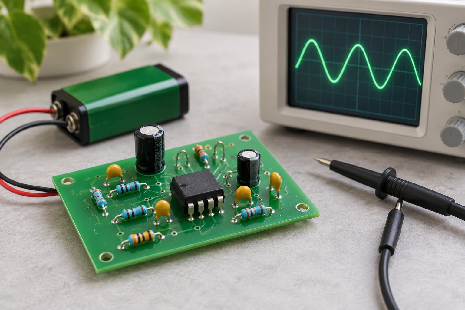
An op amp is a small integrated circuit that amplifies the difference between two input voltages by an enormous amount, and the job it actually does is set by the feedback resistors you wire around it. That single idea is op amp basics for beginners in miniature: the chip supplies vast gain, and the external network decides how much of it you keep.
Below I build that idea up in the order beginners actually need it — what the part is, what its pins do, why feedback changes everything, which gain formulas matter, and how to run your first experiment on the bench.
Table of Contents
- Op Amp Basics for Beginners: What Is an Op Amp?
- What Are the Three Op Amp Inputs?
- How Does an Op Amp Control Its Output?
- Why Is Feedback So Important in Op Amp Circuits?
- Which Gain Formulas Should Beginners Learn?
- What Are the Most Common Op Amp Configurations?
- What Specifications Matter When Choosing an Op Amp?
- Can You Use a Single-Supply Op Amp?
- What Are the Most Common Beginner Mistakes?
- How Can a Beginner Run a First Op Amp Experiment?
- Frequently Asked Questions
- Do I need to understand advanced algebra to learn op amps?
- Why does my op amp output saturate near a supply rail?
- Is a comparator the same as an op amp?
- What does input bias current mean in a practical circuit?
- How do I know whether an op amp is stable at a particular gain?
- Conclusion
Op Amp Basics for Beginners: What Is an Op Amp?
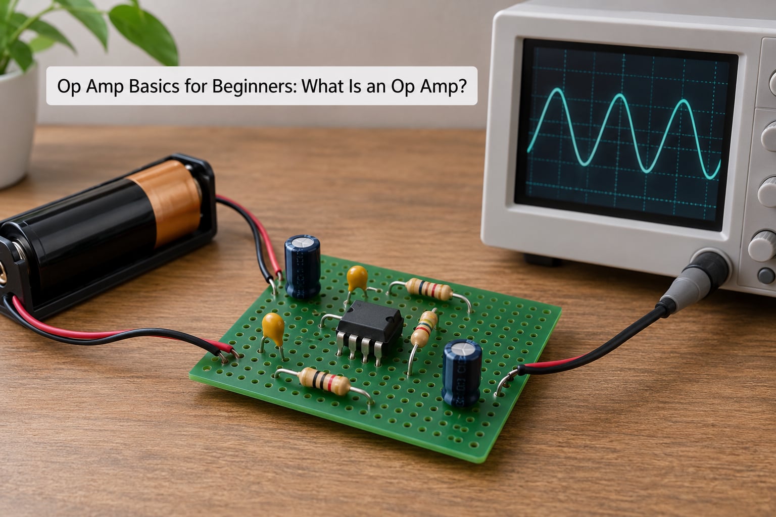
An operational amplifier (op amp) is a DC-coupled, high-gain differential amplifier: it amplifies the difference between its two input voltages, and it works all the way down to zero frequency, not just at higher frequencies like an AC-coupled audio amplifier.
The name comes from the analog computers of the 1940s, where op amps were the building blocks that added, subtracted, integrated, and scaled signal voltages to solve differential equations. The “operational” refers to the mathematical operation the whole network performs. The name misleads beginners, because the arithmetic is not built into the chip at all.
What is built into the chip is a very large, very slightly controllable gain. The function you wanted — amplification of five, filtering, or summing — comes entirely from a handful of external resistors and capacitors around it.
So an op amp on its own is not a circuit. It is a component that behaves predictably only when a surrounding network, usually a feedback loop, tells it what to do. A bare op amp with both inputs tied to the same voltage will, more often than not, slam its output into one of its supply rails and stay there.
What Are the Three Op Amp Inputs?
Almost every beginner schematic shows an op amp as a triangle pointing to one side, with two input pins entering from the other side. Alongside those sit power pins that are frequently left off simplified diagrams, which is where a lot of early confusion starts.
- Non-inverting input (V+) — the pin marked with a plus sign. Raise this voltage and the output voltage goes up.
- Inverting input (V−) — the pin marked with a minus sign. Raise this voltage and the output voltage goes down.
- Output (Vout) — the amplified, corrected result. It is measured against the negative supply, not against ground.
- Supply pins (VS+ and VS−) — the power rails that energise the internal circuitry. On a single-supply circuit VS− is tied to ground.
The two inputs work as a pair, and the output responds to the difference between them: Vout is driven by V+ minus V−, scaled up enormously. Feed 3 V into both inputs and the difference is zero. Feed 3 V into the non-inverting input and 2.98 V into the inverting input and the difference is 20 mV, which a real op amp will amplify into a saturated output.
Take a concrete 5 V example. With VS+ at 5 V and VS− at 0 V, the output cannot go below 0 V or above 5 V, and on most parts it stops roughly 1 V to 2 V short of each rail. That single fact explains more beginner surprises than any other: the inputs and the output all live inside a window bounded by two supply wires.
How Does an Op Amp Control Its Output?
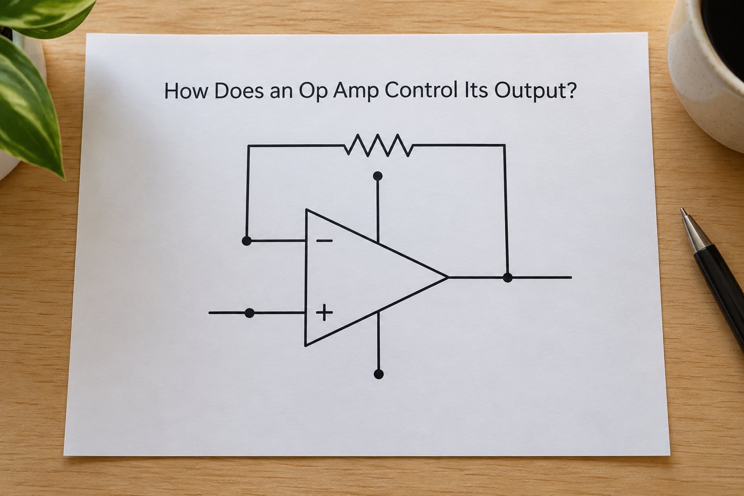
The output responds to the voltage difference between the inputs multiplied by the open-loop gain, written Vout = AOL × (V+ − V−), where AOL is typically 100,000 or higher. That multiplier is so large that a difference of a few microvolts is enough to drive the output into saturation.
Used with no feedback at all, an op amp therefore behaves as a comparator: the tiniest sign difference sends the output hard to one rail or the other. Dedicated comparator ICs are built for that job, with defined behaviour right at the rails and outputs designed to drive logic directly, so an op amp is the wrong tool for threshold switching.
Add a feedback path and the picture changes completely. Route a fraction of the output back to the inverting input, and once the output climbs, the inverting input climbs with it. That cancels the difference between the inputs, which is exactly what the op amp is trying to eliminate. In a stable, linear configuration this leads to the two rules most textbooks call the golden rules:
- In a negative-feedback configuration, the output does whatever is necessary to make the voltage difference between the two inputs zero.
- The inputs draw zero current.
Both rules are conditional. They hold only when negative feedback is present and the circuit is operating in its linear region, not saturated. Once feedback keeps the two input voltages nearly equal, engineers describe it as a virtual short. Since no appreciable current flows into either input, each input behaves like a virtual open circuit, which is what lets you analyse the surrounding resistors as though the op amp were not there.
Why Is Feedback So Important in Op Amp Circuits?
Because it converts an uncontrolled gain into a controlled one. Open-loop gain varies from part to part, drifts with temperature, and falls with frequency, so it is useless as a design parameter. The closed-loop gain of a feedback circuit depends instead on two resistor ratios, and resistor ratios are stable, cheap, and easy to calculate.
Feedback also shapes stability and bandwidth. It is what keeps an amplifier from oscillating, what defines which frequencies get amplified, and what lets a single generic part serve as a gain of 1, a gain of 100, or a filter. Without it you have a very high gain amplifier whose behaviour depends on the individual specimen and the ambient temperature — which is not something you can put in a product.
Which Gain Formulas Should Beginners Learn?
Two closed-loop formulas cover most of what beginners build. For the inverting amplifier, the input signal arrives through the inverting pin and the gain is negative, which simply means the output swings the opposite way: Av = −Rf/Rg.
For the non-inverting amplifier, the signal arrives at the non-inverting pin and the gain is always greater than one: Av = 1 + Rf/Rg. The voltage follower is the same circuit with the output wired straight back to the inverting input, giving a gain of exactly 1.
| Configuration | Gain formula | Example resistor values | Resulting gain |
|---|---|---|---|
| Inverting amplifier | Av = −Rf/Rg | Rf = 10 kΩ, Rg = 2 kΩ | Av = −5 |
| Non-inverting amplifier | Av = 1 + Rf/Rg | Rf = 4 kΩ, Rg = 1 kΩ | Av = 5 |
| Voltage follower | Av = 1 | Output tied to the inverting input | Av = 1 |
Two supporting ideas are worth knowing early. Input resistance describes how hard the circuit pulls on the signal source; the op amp’s own input resistance is enormous, so in practice the resistance you see is usually the resistor you put in series with the input. Output resistance describes how much the output voltage sags when you load it; a good op amp keeps that low enough that the load barely matters.
Also remember what those formulas do not include. They assume the op amp is not saturated and that the required output voltage fits inside the supply rails. Gain of 5 on a signal of 2 V peak needs 10 V of output swing, and a 5 V single-supply part simply cannot deliver it.
What Are the Most Common Op Amp Configurations?
Voltage follower. The output connects directly to the inverting input. The op amp changes no voltage but delivers far more current than the source can, which isolates a high-impedance sensor from a heavy load. It is the right choice whenever the problem is impedance rather than gain.
Non-inverting amplifier. Gain above one, with the input impedance untouched by the gain setting, because the signal connects directly to the non-inverting pin and draws no current. Reach for this when the source cannot supply much current or when the source impedance must not be altered.
Inverting amplifier. Gain magnitude set by the resistor ratio, with the sign reversed. Its input impedance equals Rg, so the source sees a real load and you must account for it when picking Rg. This is the configuration to reach for when you also want summing, since several inputs can share one Rf and the output becomes their weighted sum.
Summing amplifier. An inverting amplifier with more than one input resistor. With equal resistors the output is the negative sum of the inputs, and with unequal resistors it is a weighted sum. Averaging circuits, mixer stages, and DACs are all built this way.
Difference amplifier. Subtracts one voltage from another, and with four matched resistors rejects the common voltage that both signals share. Matching precision matters here more than anywhere else, because resistor mismatch directly becomes gain error.
Comparator. No feedback at all. The output reports which input is higher. Expected behaviour is the output sitting hard at a rail, and any expectation of proportionality is a mistake.
Integrator. A capacitor in the feedback position instead of a resistor. The output becomes the running integral of the input, used for ramps, oscillators, and simple control loops. Practical integrators also carry a large resistor in parallel with the capacitor to stop drift.
What Specifications Matter When Choosing an Op Amp?
Datasheets run to forty pages, but a beginner only needs a handful of parameters. Pairing each ideal textbook assumption with its real value makes the rest of the sheet less intimidating, and it is op amp basics for beginners condensed into one table.
| Parameter | Textbook ideal | Typical real value | Why it matters |
|---|---|---|---|
| Open-loop gain | Infinite | 20,000 to 200,000 and above | Sets how much feedback is needed to reach a usable closed-loop gain |
| Input bias current | Zero | About 10 nA for bipolar inputs, tens of pA for JFET, a few pA for CMOS | Flowing through a high source resistance, it creates an error voltage |
| Input offset voltage | Zero | Tens of microvolts to a few millivolts | With both inputs tied together it alone can drive the output to a rail |
| Bandwidth | Infinite | Set by the gain-bandwidth product | A 1 MHz GBWP part gives gain of 5 only up to about 200 kHz |
| Slew rate | Infinite | 5 to 100 V/µs is common; a TL081 manages about 13 V/µs | Too slow, and large fast signals distort into a triangle wave |
| Common-mode rejection | Infinite | Often 80 dB to 120 dB | Limits how much shared signal survives the amplifier |
| Supply rejection | Infinite | Finite, and worse at higher frequency | The reason supply decoupling capacitors are not optional |
Gain-bandwidth product deserves a second look. In most voltage-feedback op amps, bandwidth falls in direct proportion as closed-loop gain rises: doubling the gain halves the usable bandwidth. That single trade-off explains why a high-gain stage usually needs several lower-gain stages in series rather than one big one.
Slew rate is a separate limit, and it is about the largest signal the part can move quickly, not about small-signal bandwidth. A part with a 0.001 V/µs slew rate, common in micropower designs, can be perfectly adequate at 1 kHz and useless at audio frequencies.
One more family of parts behaves differently. Current-feedback amplifiers hold their bandwidth roughly constant as gain rises rather than trading bandwidth for gain, which makes them the better choice for high-frequency, high-gain work — and the wrong choice for a first circuit.
Can You Use a Single-Supply Op Amp?
Yes, and most modern circuits do. The important part is that nothing changes in the theory. Feedback, gain formulas, and the golden rules all behave identically. What moves is the reference point that your signals are measured against.
An op amp has no built-in idea of ground. We call some arbitrary node in the circuit 0 V and call everything else relative to it. With two supplies the output can swing both up and down around that node, so bipolar signals pass through untouched. With one supply, the output physically cannot go below the negative rail, which is usually ground — so a signal centred on 0 V has nowhere to swing.
The standard fix is biasing: shift the whole signal up so it sits in the middle of the available range. A 2 V peak sine wave riding on a 2.5 V reference, for example, swings from 0.5 V to 4.5 V and stays inside a 5 V supply. On the output side the bias is usually removed again, by a capacitor or by the next stage that is referenced the same way.
Two cautions apply to most parts. Most op amps, especially older dual-supply designs, are not rail-to-rail: they saturate 1 V to 2 V short of the rail, and their input common-mode range is a separate limit that can be narrower still. A part described as a single-supply op amp is simply one designed to work closer to the rails than average, not one that reaches them. In 3.3 V and 1.8 V systems, low-voltage parts with rail-to-rail inputs and outputs are the sensible default.
Mid-supply references are usually generated with two equal resistors and a bypass capacitor. Resistive dividers alone would be loaded by the bias current, which is why a capacitor is added, and why a buffered voltage follower is often used instead when accuracy matters.
What Are the Most Common Beginner Mistakes?
Almost every strange op amp behaviour traces back to one of a small number of causes. Work through this list before reaching for the datasheet’s application notes.
- Feedback wired to the wrong pin. Feedback from output to the non-inverting input is positive feedback, and the circuit runs to a rail instead of amplifying. Symptom: output pinned at one extreme. Fix: route feedback to the inverting input.
- Missing supply decoupling. A small ceramic bypass capacitor, typically 0.1 µF, from each supply pin to ground, placed as close to the pin as physically possible, plus a larger bulk capacitor near the supply. Symptom: a circuit that works on the bench and oscillates, hums, or behaves differently from breadboard to breadboard. Fix: add the capacitors before blaming the topology.
- Expecting output swing to the rail. Symptom: flat-topped clipping even though the calculated voltage is within the supply. Fix: allow 1 V to 2 V of headroom, or pick a rail-to-rail part.
- Forgetting the common-mode input range. Symptom: an output that phase-reverses and latches at the wrong rail, a confidently wrong answer rather than an obvious error. Fix: check that both input voltages stay inside the published range at all times.
- Using a non-unity-gain-stable part at gain of 1. Some op amps need a minimum gain of about 5 to stay stable. Symptom: oscillation or a ringing output in what should be the simplest circuit in the design. Fix: check the datasheet for a unity-gain-stable variant.
- Overloading a source. The inverting amplifier’s input resistance is just Rg. Symptom: a source voltage that falls short of the predicted level. Fix: raise Rg and Rf together to keep the same ratio.
- Running too close to the gain-bandwidth product. Symptom: oscillation, or a clean signal at low frequency that distorts at higher frequency. Fix: close the loop gain by adding a compensation capacitor in the feedback network.
- Expecting offset-free, instant output. Offset voltage and slew rate are real, finite, and usually temperature-dependent. Expect a small standing error and a limit on how fast the output can move.
How Can a Beginner Run a First Op Amp Experiment?
Build a voltage follower first. It needs one op amp, two resistors, a low-voltage supply, and a meter, and because the gain is 1 the correct answer is trivially checkable.
What you need. A unity-gain-stable op amp in an 8-pin DIP package, such as a single or dual version of a common low-voltage part. A regulated 5 V supply, or a current-limited bench supply. Two 10 kΩ resistors, a 10 µF electrolytic and a 0.1 µF ceramic capacitor, a small piece of breadboard, and a digital multimeter. A general-purpose dual or quad part in the DIP package lets you build more than one circuit from a single chip.
Connections. Connect the positive supply pin to +5 V and the negative supply pin to ground. Place the 0.1 µF ceramic from the positive supply pin directly to ground at the chip, and the 10 µF electrolytic across the supply rails nearby. With the power off, connect the output pin straight to the inverting input. From the non-inverting input, put a 10 kΩ resistor to ground, and a second 10 kΩ resistor from the non-inverting input to the point where your input signal will connect.
What you should see. Power up and measure the output. With no input signal, a healthy part sits near the supply voltage, because the bias current through the 10 kΩ resistor produces a small voltage that the follower passes straight through. Apply a small DC voltage to the input divider, say around 1 V, and the output should read essentially the same, well inside the 5 V rail. Change the input and the output should follow it, unchanged in magnitude.
Success criteria. Output within a few millivolts of the input, and a steady reading with no drift. If the output is pinned at 5 V or at ground, check that feedback reaches the inverting input and that both supply pins are connected. If the output follows but reads a few hundred millivolts high, that is expected input bias current flowing through the 10 kΩ resistor, and it is a good first lesson in why bias current matters.
Safety. Keep the supply under 12 V, use a current limit if your supply has one, and switch power off before rearranging jumpers. Nothing here is mains-connected or high-voltage, but a short across a supply pin can still damage the regulator or the chip.
Once the follower works reliably, change one thing at a time: add a 4 kΩ feedback resistor and a 1 kΩ resistor to ground for a non-inverting gain of 5, then move the input to the inverting side with 10 kΩ and 2 kΩ resistors and check for an inverted output of five times the input.
Frequently Asked Questions
Do I need to understand advanced algebra to learn op amps?
No. Almost everything a beginner builds is done with two resistor ratios and Ohm’s law. You need to recognise that current entering a node must leave it, and that two voltages in series add up. Those two ideas cover inverting, non-inverting, and summing amplifiers, filters, and most first designs. The simultaneous-equation approach that appears in textbooks is a convenience for more complex circuits, not a prerequisite for the basics.
Why does my op amp output saturate near a supply rail?
Because the op amp is trying to push its output further than the rails allow, or because it is receiving the wrong information. Common causes: the calculated gain demands more output voltage than the supply can deliver; the circuit runs from a single supply with no bias voltage, so the output cannot swing below ground; an input sits outside the published common-mode range, which can phase-reverse the output; or a part that is not unity-gain stable is being used at a gain of 1.
Is a comparator the same as an op amp?
They behave the same way in principle but not in practice. Without feedback, an op amp acts as a comparator, driving its output to whichever rail the input difference suggests. Comparator ICs are built specifically for that job, with faster switching, defined behaviour at the rails, and outputs able to drive logic directly. An op amp used as a comparator wastes current and leaves the output in its linear region when the inputs are nearly equal.
What does input bias current mean in a practical circuit?
It is the small current an input pin draws from the circuit feeding it — roughly 10 nA for bipolar inputs, tens of picoamps for JFET, a few picoamps for CMOS. On its own it is harmless. The problem appears when it flows through a high source resistance, because a small current across a large resistance becomes a significant voltage. A 10 nA bias current through a 1 MΩ resistor produces a 10 mV error before the amplifier even sees the signal.
How do I know whether an op amp is stable at a particular gain?
Check whether the datasheet describes the part as unity-gain stable, and check the gain-bandwidth product against your signal frequency. At closed-loop gain G, the usable bandwidth is roughly the gain-bandwidth product divided by G, so a part with 1 MHz of gain-bandwidth product delivers about 200 kHz at a gain of 5. Stability itself depends on the compensation capacitor and the feedback network, which is why the manufacturer publishes a recommended feedback resistor range.
Conclusion
Start by internalising two ideas: the output responds to the difference between the two inputs, and feedback is what turns that response into something you control with resistors. Build the voltage follower, verify the output matches the input with a meter, and only then add gain.
After the follower, work through the inverting and non-inverting amplifiers, then the summing amplifier and the difference amplifier — those four unlock most practical analog work. Once single-supply operation stops feeling strange, the remaining behaviour you will meet — offset, bias current, slew rate, common-mode limits — all trace back to a real, documented non-ideality rather than to anything mysterious. Free references from Texas Instruments and Analog Devices cover all of it in more detail than this page can.