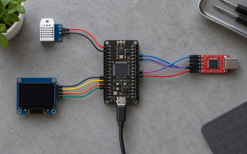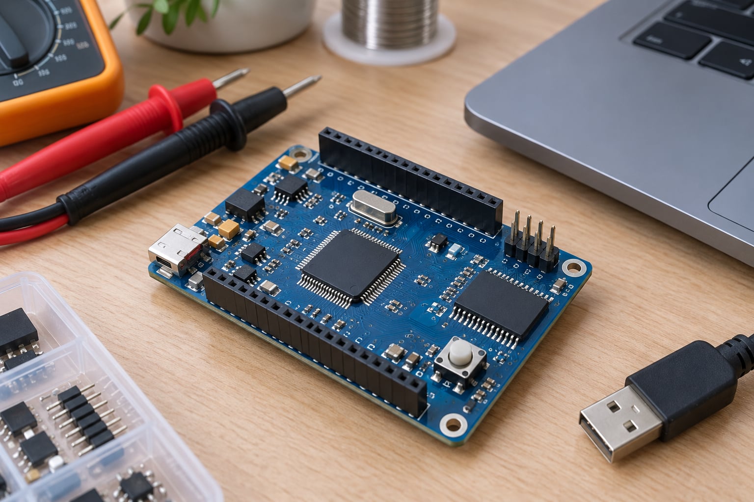
A microcontroller bootloader is a small, permanent program stored in its own region of flash memory that runs first at power-on or reset. It brings up just enough hardware to decide whether to install new firmware or hand control to the application, and then it gets out of the way. Understanding bootloader basics for microcontrollers is mostly about understanding where code lives in flash and what the CPU does with the reset vector before anyone calls main().
Below is the version of the story I wish I had when I first had to add one to a board: what runs at reset, how a typical flash layout is carved up, how updates travel in and get validated, and what to do when a power cut lands halfway through a flash write.
Table of Contents
- What Is a Microcontroller Bootloader?
- How Does a Microcontroller Bootloader Work?
- Bootloader Basics for Microcontrollers: Common Memory Layouts
- What Does the Bootloader Do at Startup?
- How Do Bootloader Updates Work?
- Bootloader vs Application Firmware
- How Do You Design a Microcontroller Bootloader?
- What Security Features Should a Bootloader Use?
- How Do You Debug and Test a Bootloader?
- Frequently Asked Questions
- Where is the bootloader stored on a microcontroller?
- Do all microcontrollers require a bootloader?
- How long does a bootloader add to boot time?
- How much flash does a bootloader need?
- Can an interrupted firmware update brick a microcontroller?
- What is the difference between a bootloader and a bootloader loader?
- Conclusion
What Is a Microcontroller Bootloader?
A microcontroller bootloader is a small program stored in a protected region of internal flash that executes on every reset. It initialises the clocks and peripherals it needs, decides whether to accept a new firmware image, and finally jumps to the application firmware.
The key distinction is that the bootloader is not your application. It is code you write once, ship in every unit, and expect to stay put while the application behind it changes many times over the product’s life.
Three terms get mixed up constantly, so it is worth pinning them down early. The bootloader is the permanent first-stage code. The application firmware is the product you are shipping, from a sensor node to a motor controller. Device firmware is sometimes used for either of those, which is why technical documents tend to say boot manager or boot loader when they mean the first-stage code specifically.
You also meet in-system programming (ISP) and in-application programming (IAP). ISP means programming flash while the chip is in circuit, usually over the same pins the bootloader uses. IAP means the running application itself writes new code into flash. They are different techniques, and the boundary between them and the bootloader is where a lot of confusion starts.
How Does a Microcontroller Bootloader Work?
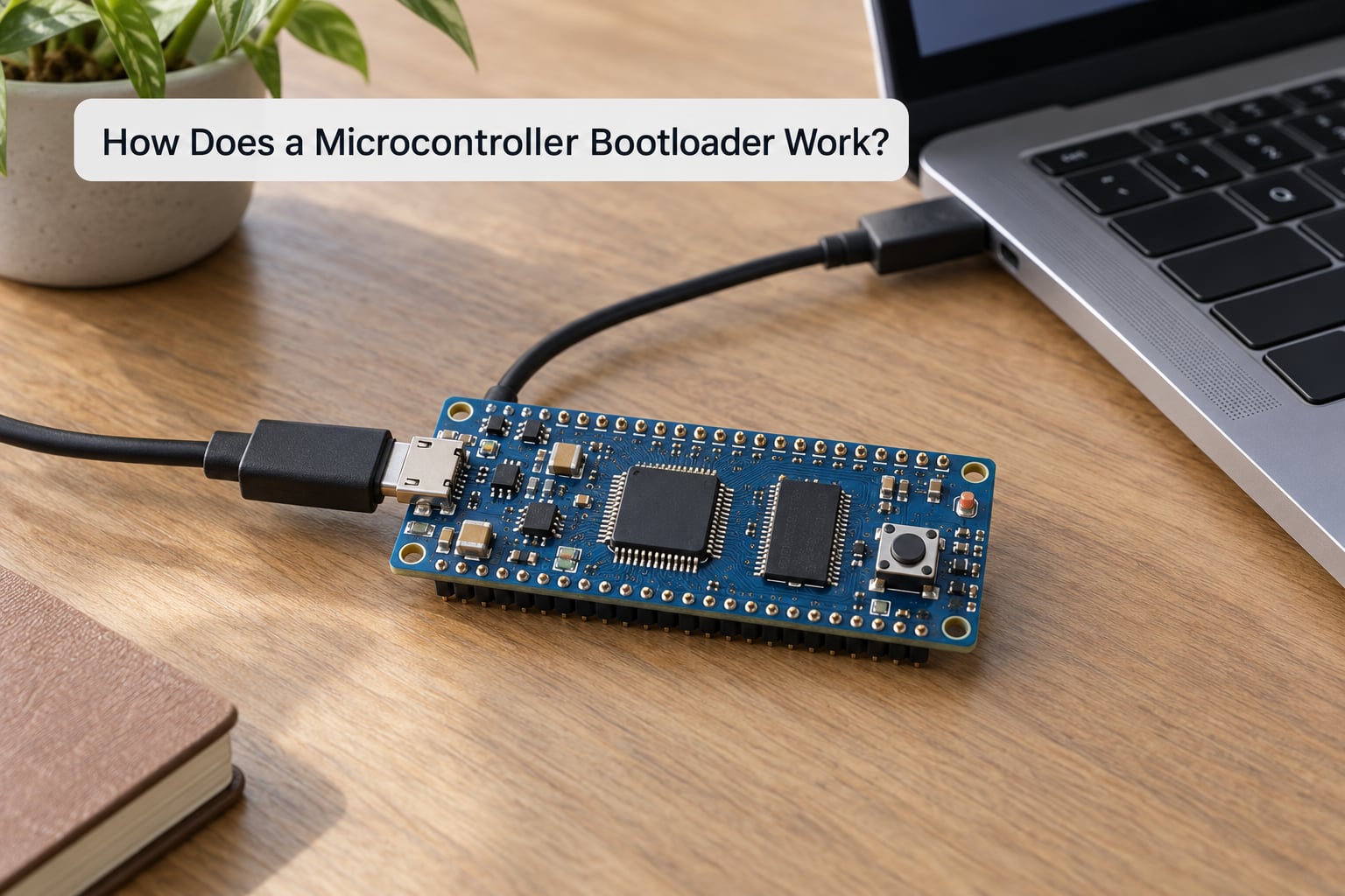
Nothing loads the bootloader. It is already in flash, and the CPU goes there on its own the moment power stabilises. On reset the processor fetches an initial stack pointer from one fixed address and a reset vector from the next, loads both into registers, and jumps to the address in the reset vector. On ARM Cortex-M that is the first two words of the vector table at address 0x00000000.
The sequence from there is short, ordered, and worth memorising because every bootloader bug shows up somewhere along it:
- Reset and hardware bring-up. The core is clocked from an internal oscillator. The bootloader configures the flash controller and the peripherals it needs for its own transport, typically UART or USB, before touching anything optional.
- Boot-mode decision. It samples the boot pins, a magic value in a configuration block, or a button held at reset, to decide whether to enter update mode or run normally.
- Memory and sanity checks. It verifies that the application region holds a plausible image: a valid header, a matching length, an acceptable checksum or signature. A blank or corrupt region means there is nothing to run.
- Optional update. In update mode it erases the staging area, receives the new image over the transport, verifies it, and marks it good in a metadata block.
- Handoff. It relocates the application vector table, loads its stack pointer and reset handler, and jumps. The bootloader is finished and will not run again until the next reset.
Step 5 is where beginners lose hours. On Cortex-M, the vector table lives at the start of the application image in flash, and the CPU always reads vectors from address zero. Point VTOR (the vector table offset register) at the application’s base address before the jump, or interrupts land in the bootloader’s handlers and the application hard-faults on its first interrupt.
On AVR parts the equivalent trick is the boot reset vector fuse, a single bit that tells the chip to jump past the bootloader at reset. Arduino’s Optiboot is a well-known example, and it is also why you can opt a board out of the bootloader entirely by changing fuses. On RISC-V designs the reset value comes from a fixed trap vector set by the chip’s ROM, which is why vendor ROM monitors are common there.
Bootloader Basics for Microcontrollers: Common Memory Layouts
Flash partitioning is the decision everything else depends on. Below is a realistic layout for a 128 KB Cortex-M part running a 70 KB application, with a 16 KB bootloader and room for a staging copy of the image.
| Region | Start | Size | Contents |
|---|---|---|---|
| Bootloader | 0x0800 0000 | 16 KB | First-stage code, transport drivers, image verification |
| Application | 0x0800 4000 | ~80 KB | Main firmware plus its vector table at offset zero of the region |
| Staging bank | 0x0801 8000 | ~24 KB | Incoming image during an update, or a backup copy for A/B rollback |
| Configuration | 0x0801 F000 | 4 KB | Version counters, boot flags, calibration, key hash |
Three points here are worth internalising. The bootloader must sit at address zero, because that is where the CPU looks on reset; if you need your application there instead, you move the vector table with VTOR instead. The bootloader region is usually write-protected by option bytes so that a stray write in application code cannot overwrite it. And the configuration block is the one region the bootloader must be able to write during normal operation, so it needs its own erase granularity and wear budget.
Where an application does not fit alongside a second copy, you have three choices. Skip the staging area and receive the image directly into the application region, accepting that an interrupted write leaves nothing to run. Use a dual-bank A/B scheme where two full application slots alternate, which needs roughly twice the application flash. Or use an external flash chip over SPI or QSPI, where you stream the image into it and copy it across at the next boot.
Sizing the bootloader is a real constraint on small parts. A transport driver, a signature check with ECDSA, a version handler and logging will push a lean design to several kilobytes; a full network stack or a filesystem does not fit under 16 KB at all. One useful rule of thumb: reserve 10 to 15 percent of total flash for the bootloader and round it up, then treat that number as fixed and design the application around it.
What Does the Bootloader Do at Startup?
At startup a bootloader does considerably more than jump. The usual list, in the order it happens:
- Clock setup. Switch from the internal oscillator to the external crystal or PLL if the application needs accurate timing. Many designs deliberately leave clocks at their reset defaults, since the bootloader finishes in milliseconds.
- Memory checks. Confirm flash is accessible, and if the part has ECC or parity, that no uncorrectable error is flagged. A quick destructive RAM test catches dead silicon.
- Minimal peripheral init. Bring up only the pins for the boot-mode input and the update transport. Touching every peripheral here wastes boot time and creates more code to test.
- Boot-mode selection. Check the hardware pin, the reset button, and the configuration flags, in a defined priority order.
- Watchdog handling. Either feed the watchdog deliberately during long flash operations, or disable it, so a slow erase cycle does not reset the part mid-write.
- Security checks. Verify that debug access is locked down, validate the image header, and check the signature and version before executing anything.
- Handoff. Set the vector table offset, set the application stack pointer, and branch.
Boot time is usually not a concern for industrial or sensor products. On a 128 KB Cortex-M part with a 16 KB bootloader, a fixed-point image check adds a few milliseconds, and a signature verification with hardware acceleration adds a few more. It does matter for anything that sleeps between wakeups and drains a battery, which is where the “check everything, every boot” habit starts to cost real energy.
How Do Bootloader Updates Work?
An update is a transfer, a verification and a state change. Getting the last part wrong is what bricks devices, so treat the sequence as the design, not an afterthought.
| Interface | Typical use | Notes |
|---|---|---|
| UART | Production lines, recovery, low-cost boards | Simple framing, host-side tool, slow at high baud rates on noisy cables |
| USB DFU | Consumer devices, development boards | Higher throughput, needs a stable descriptor and more driver code |
| CAN | Automotive, industrial buses, motor vehicles | Low bandwidth, needs frame-level retry handling and CAN controller support |
| SPI / QSPI to external flash | Large images, dual-bank staging | Fast, cheap, needs a separate data path from the command path |
| Ethernet / Wi-Fi | Fleet and OTA updates | Largest code footprint, biggest attack surface |
| SWD / JTAG | Development and rescue | Not a bootloader transport, but the path that recovers a truly dead board |
Whatever the transport, the framing is similar: a sync pattern, a command byte, a length, a payload, and a checksum over the payload. Vendors usually publish the exact protocol so third-party tools can drive the chip without the original toolchain. The STM32 system memory bootloader is the best-documented example, with a documented command set over UART, USB and even CAN; using it means your board needs no custom bootloader code at all.
Verification is where the interesting decisions sit. A CRC catches accidental corruption and costs almost nothing. A digital signature catches a hostile image and costs kilobytes of flash plus a key you must keep out of reach. Doing the signature check in the bootloader is the only place it means anything, because application code is exactly what an attacker would replace.
The failure case is the one nobody documents. Flash erase and program cycles take milliseconds per block, so a power cut or a dropped cable mid-write leaves a half-written image. The recovery pattern that works is dual-bank with a marker: receive the new image into the inactive slot, write a “pending, version N” flag, only then copy or activate it, and clear the flag once the application confirms it is running. On the next boot, a pending flag with no confirmation means the update failed, and the bootloader reverts to the last known-good slot.
On threads about CAN bootloader protocols, the recurring advice is to keep the frame payload small enough to fit comfortably in one buffer and to handle the case where the host retries a command you already processed. Idempotent commands are far easier to recover from than clever ones.
Bootloader vs Application Firmware
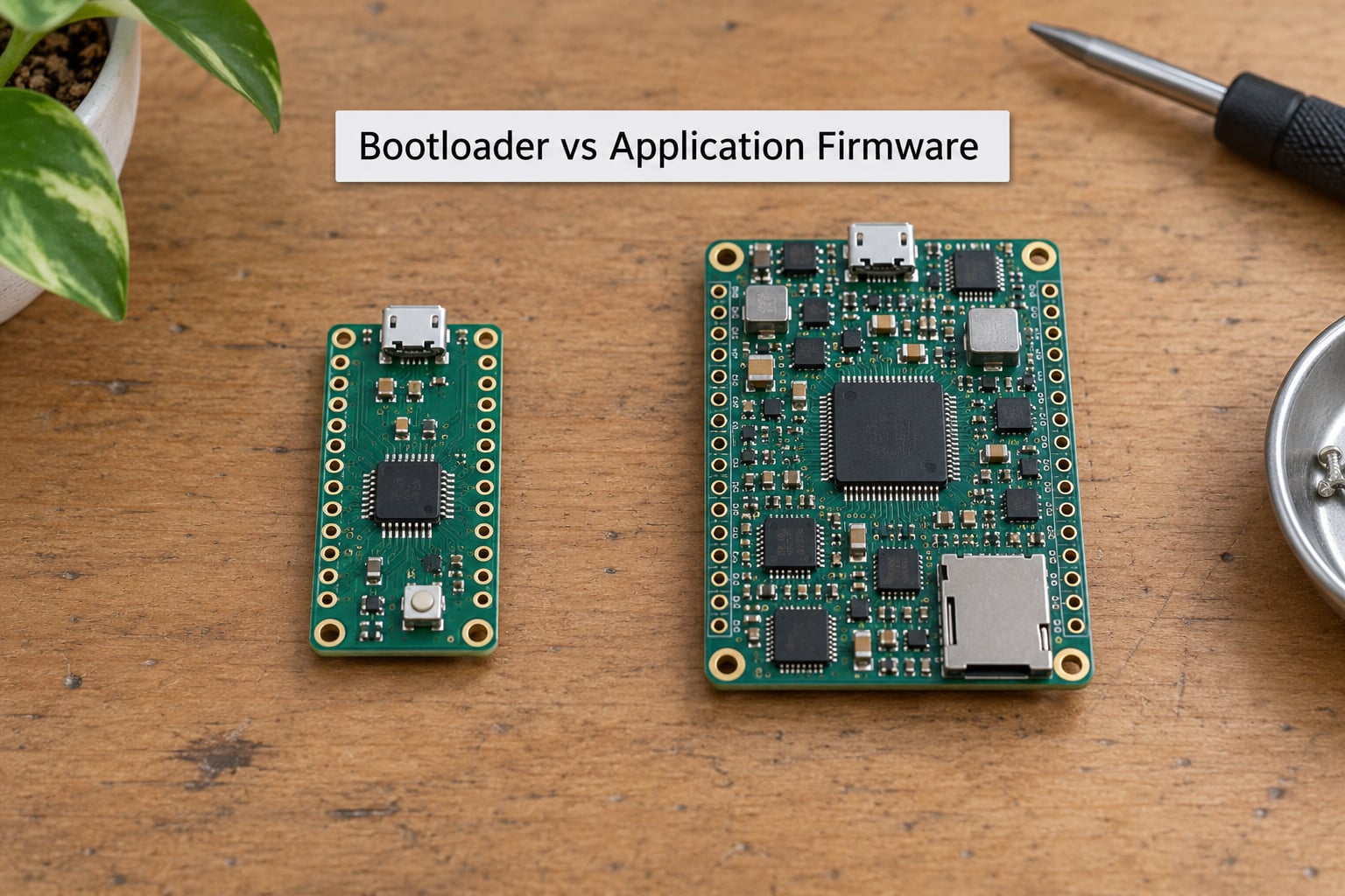
The bootloader and the application do completely different jobs, and mixing them makes both worse. Here is the honest comparison.
| Bootloader | Application firmware | |
|---|---|---|
| Primary role | Decide what to run, load it, hand off | Do the product’s actual job |
| Runs | Every reset, for milliseconds | Continuously after handoff |
| Update frequency | Almost never, and factory-programmed | Frequently, often in the field |
| Size budget | Tight, often 8 to 16 KB | Whatever is spare |
| Failure impact | Total: the device may have no valid application | Partial: features break, the bootloader still runs |
| Dependencies | Minimal hardware init, no RTOS, no libraries | RTOS, drivers, network stack, third-party code |
| Tested how | Power-loss and malformed-image tests, few builds | Feature, integration and regression tests |
Engineers describe the bootloader as the most bug-prone code in an embedded project, because the footprint is tiny and the blast radius is the whole product. One accidental erase loop or a wrong jump address takes every unit in the field offline at once. The practical response is to keep it as boring as possible: no dynamic allocation, no interrupts beyond what the transport needs, and a jump function that is short enough to read in one go.
How Do You Design a Microcontroller Bootloader?
Work through these in order. Later steps depend on earlier ones.
1. Write down the requirements. Does the device ever get updated after it ships? Over which interface? Does it need security? Roughly how large is the application over its lifetime? If the answer is no field updates, a factory-programmed image with a JTAG header is a legitimate design and saves you the whole layer.
2. Fix the memory map. Decide the bootloader size, application region and configuration block, then write a linker script that enforces it and fails the build if the application outgrows its region. This is the step people skip and regret.
3. Decide the reset behaviour. What makes the bootloader enter update mode: a pin, a button, a held reset, a command in the config block? Define the priority order when several are true at once.
4. Implement the transport and the protocol. Start with one interface. Add framing, a timeout, a retry rule and a checksum before you add anything else.
5. Add version tracking. Store a version number and a build identifier in the config block, and reject images older than the running one if rollback protection matters to you.
6. Validate before you execute. Header check, length check, checksum, then signature. Every one of these is a separate decision, and skipping the header check is how malformed images reach the jump.
7. Build the recovery path. Dual-bank or at minimum a marker-based flag. Then test that path by actually killing power mid-write, because a recovery path that has only been reasoned about is not a recovery path.
8. Plan production. A bootloader that only works on the engineering bench is not done. Decide whether production uses the bootloader itself or a separate SWD step, and add a boot-time log or LED pattern that lets manufacturing identify a failed unit quickly.
On whether to build or adopt: MCUboot is a good fit for Zephyr-based constrained devices and gives you signing and A/B updates out of the box. U-Boot and Barebox are for larger Linux-capable systems and cost hundreds of kilobytes. Vendor ROM bootloaders such as the STM32 system monitor cost zero bytes of your flash and give up customisation. Optiboot is a small, well-understood AVR bootloader. On a small MCU with one transport and no signing requirement, a few hundred lines of your own C is often less work than bending one of these to fit.
What Security Features Should a Bootloader Use?
A bootloader is the highest-value code on the board, because it decides what executes next. If an attacker can replace the application, they inherit every device capability it has. The protections that matter, roughly in order of importance:
- Signed images. The bootloader carries a public key hash and refuses to boot an image without a valid signature over it. This is secure boot; the rest of the list is detail around it.
- A protected root of trust. The public key or its hash lives in write-protected flash or OTP, and the bootloader region itself cannot be erased by application code. A private signing key never ships on the device; it stays on a build server or a signing host.
- Rollback protection. Store a monotonic version counter and reject anything lower, so a signed but old vulnerable image cannot be reinstalled.
- Authenticated updates. A signature alone tells you the image came from you. Encrypting the transport as well prevents anyone reading what your firmware contains while it is in flight.
- Debug lock. Lock out SWD and JTAG once the unit ships, otherwise a physical attacker skips the bootloader entirely and programs flash directly.
- Secure recovery. A recovery path that accepts any unsigned image over UART is a downgrade attack. Your fallback path should be as strict as your normal path.
None of this needs a dedicated security chip, though adding one changes the trust model substantially. On a plain microcontroller, the practical floor is: signed images, write-protected bootloader region, locked debug, and a monotonic version counter.
How Do You Debug and Test a Bootloader?
Bootloader bugs are almost always visible in two places: the moment of handoff, or the moment an update finishes. Testing should aim at both.
First, get eyes on the boot itself. An SWD probe with a reset-under-control option lets you halt the core within a few microseconds of the reset edge and read the stack pointer and PC directly. If those two values are wrong, nothing else in your reasoning matters. Set hardware breakpoints at your handoff routine rather than software breakpoints, since flash is not writable while it executes.
Second, instrument. A UART log line at each stage, with the flash addresses of the bootloader, application and image length, turns a silent hang into a two-second diagnosis. On a production line, the same output over a single GPIO toggled at each stage costs almost nothing and finds dead units fast.
Third, test the matrix rather than the happy path. Every combination of boot pin, button state, config flag and image validity should have a defined outcome, and you should confirm each one on hardware. Then run the destructive tests: pull power at each stage of an update, corrupt bytes at random offsets in the image, send a header with a length longer than the buffer, and send an image with a valid structure but a bad signature. Every one of these should end in a device that still boots something recoverable.
Finally, test the factory path. A bootloader that takes ten seconds to enumerate USB and cannot be interrupted makes production programming painfully slow, and a bootloader that always checks for an update request before booting will fail the line. Measure the time from reset to handoff for the normal case and write it into your test log as a regression check.
Frequently Asked Questions
Where is the bootloader stored on a microcontroller?
In a dedicated region of internal flash at address zero, so the CPU’s reset vector points straight at it. On many parts that region can be write-protected through option bytes, which stops application code from overwriting it. Some chips also ship a bootloader in masked ROM or a separate system memory area that the vendor programs.
Do all microcontrollers require a bootloader?
No. A microcontroller boots whatever is at the reset vector, and factory programming over SWD or JTAG is a complete way to ship a product. A bootloader becomes necessary when the device must be updated after it leaves your hands, when production needs a fast serial path, or when you want a recovery route once a unit is in the field.
How long does a bootloader add to boot time?
On a small Cortex-M part with a lean bootloader, a header check and a signature verification typically add a few milliseconds to the time between reset and the application running. Wireless or network-capable bootloaders that wait for a link to come up add far more, which matters for battery-powered devices that wake frequently. Measure it on your own hardware rather than trusting a figure from a datasheet.
How much flash does a bootloader need?
A bare serial bootloader can fit in two to four kilobytes. Adding USB, a network stack and a signature check with hardware acceleration pushes a typical design to eight to sixteen kilobytes. Reserve ten to fifteen percent of total flash and round up, then design the application around that fixed number so it never becomes a surprise late in the project.
Can an interrupted firmware update brick a microcontroller?
Yes, if the bootloader writes the new image straight into the only copy of the application. A power cut during a flash erase leaves a partially written image that will fail every boot check. Dual-bank A/B updates avoid this by receiving the image into an inactive slot and only marking it good after a successful copy, so a failure reverts to the last working version.
What is the difference between a bootloader and a bootloader loader?
They are two stages of the same idea. The bootloader is the first-stage program that runs at reset. A bootloader loader, sometimes called a second-stage or monitor, is loaded by the first stage to do the heavier work, such as parsing an OS image, setting up a network stack or loading a real operating system. Tiny MCUs never need the second stage; Linux-class systems almost always do.
Conclusion
Start with the memory map, not the code. Decide where the bootloader lives, how much flash it gets, and what tells the chip to enter update mode, then write a linker script that holds your application inside its region. Everything after that, transports, verification, dual-bank recovery and signed images, builds cleanly on top of a layout you have already committed to.
Last updated: October 2026