If you have read this far, the short version is: I2C wins on wire count, SPI wins on speed, and UART wins on simplicity. I2C (Inter-Integrated Circuit) is a two-wire addressed bus for lots of low-to-medium-speed devices, SPI (Serial Peripheral Interface) is a four-wire full-duplex bus for fast transfers to a handful of devices, and UART (Universal Asynchronous Receiver/Transmitter) is a two-wire clockless point-to-point link.
This guide is written for engineers, students and hardware developers who need to defend an interface choice in a design review, not just understand the acronyms. Everything below stays at the signal level: how many wires each one costs you, what the realistic speeds are, how devices get addressed, and where each protocol falls over on a real board.
If you like the concrete numbers up front, the table below is the whole comparison in one place. The sections after it explain why each row looks the way it does.
Table of Contents
- i2c vs spi vs uart explained at a Glance
- What Is I2C and How Does It Work?
- How an I2C transfer works, step by step
- Why I2C uses open-drain signalling and pull-up resistors
- What Is SPI and How Does It Work?
- The four SPI modes: CPOL and CPHA
- Where SPI scales, and where it does not
- What Is UART and How Does It Work?
- What 9600 8N1 actually means
- I2C vs SPI vs UART: Wiring and Connections
- I2C vs SPI vs UART: Speed and Data Transfer
- I2C vs SPI vs UART: Addressing Multiple Devices
- I2C vs SPI vs UART: Distance, Noise, and Reliability
- I2C vs SPI vs UART: Advantages and Disadvantages
- Common failure modes, and how to debug them
- The same sensor read, in all three protocols
- Which Should You Choose?
- Frequently Asked Questions
- Can I2C, SPI, and UART be used at the same time?
- Which is faster, SPI or I2C?
- Does UART need a clock wire?
- Why do I2C wires need pull-up resistors?
- Is I2C faster than UART?
- How many devices can you connect to one I2C bus?
- Conclusion
i2c vs spi vs uart explained at a Glance
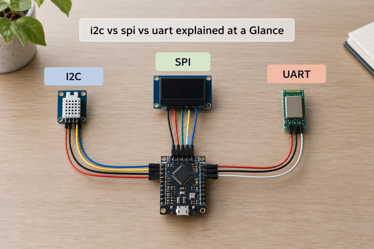
| Criterion | I2C | SPI | UART |
|---|---|---|---|
| Signal lines to controller | 2 (SDA, SCL) | 3 shared (SCLK, MOSI, MISO) plus one CS per device | 2 (TX, RX) plus common ground |
| Clock on the wire | Yes, SCL | Yes, SCLK | No, agreed baud rate only |
| Topology | Multi-drop bus | Multi-drop bus | Point-to-point link |
| Duplex | Half-duplex | Full-duplex | Full-duplex |
| Addressing | 7-bit or 10-bit address in the data stream | Chip select line per device | None built in |
| Named speed modes | 100 kHz, 400 kHz, 1 MHz, 3.4 MHz | Controller-generated, commonly 1 to 100+ MHz | 9600 bps up to a few Mbps |
| Realistic device count | About 126 on a 7-bit bus | Limited by chip select pins | 2 unless you add hardware |
| Practical cable length | Short board traces, roughly 1 m ceiling | Very short, on-board only | About 15 m at TTL levels |
| Typical peripherals | Sensors, EEPROM, RTC, I/O expanders | Displays, SD cards, high-speed ADC, flash | Debug console, GPS, Bluetooth, modems |
| Extra hardware needed | Pull-up resistors | Chip select GPIO per device | Level shifter or transceiver for long links |
One row deserves emphasis before anything else: UART has no chip select and no address. That single fact explains most of the design differences between the three, from pin count to how you add a second device.
What Is I2C and How Does It Work?
I2C, or Inter-Integrated Circuit, is a synchronous serial bus defined by Philips and now maintained by NXP. It carries data on SDA (Serial Data) and clock on SCL (Serial Clock), and it is the only one of these three that is genuinely multi-device by design.
Yes, I2C uses serial communication. Every bit of the address, the register pointer and the data payload travels along the same single data line, one bit at a time, timed by the clock. That is what buys you the two-wire bus, and it is also the source of most I2C’s speed ceiling.
Because it is a bus, the two lines are shared by every device on it. Devices are distinguished by a 7-bit address sent by the controller at the start of each transfer. Devices that share a fixed address cannot both sit on the same bus unless you change one of them, which is the single most common wiring mistake people make.
How an I2C transfer works, step by step
- Start condition. The controller pulls SDA low while SCL stays high, telling every device on the bus that a transfer is beginning.
- Address byte. The controller sends the 7-bit address, shifted left with a read/write bit in the lowest position. A 10-bit address is available in the specification for larger systems.
- ACK or NACK. The addressed device pulls SDA low to acknowledge. A NACK means nobody answered, with SDA released high, and the controller usually aborts.
- Data bytes. Each byte is followed by another ACK. Registers on most sensors are read by writing the register pointer first, then reading the data bytes back.
- Stop condition. SDA rises while SCL is high, releasing the bus for the next transfer.
I2C is half-duplex. SDA carries traffic in both directions, but only one direction at a time, so the bus cannot send and receive simultaneously the way SPI can.
Why I2C uses open-drain signalling and pull-up resistors
Every device on an I2C bus can pull SDA or SCL low, and no device ever drives them high. Both lines idle high only because of external pull-up resistors. That design is what allows multiple devices to share a bus without fighting each other, and it is also why the bus has a hard capacitance ceiling.
Rise time is set by the resistor value and total bus capacitance. Weak pull-ups with a long cable or several devices produce slow, rounded edges that fail timing margins, which is exactly the intermittent NACK pattern engineers chase for days. Typical designs land between 2.2 kΩ and 10 kΩ, with 4.7 kΩ a common default, and the specification caps bus capacitance at 400 pF in standard mode.
Clock stretching is worth knowing about too. A slow peripheral can hold SCL low to buy itself time, and a controller that ignores that behaviour will sample garbage. A few controllers also support multi-master operation, where two controllers arbitrate over the bus, but that is rare in a single-board design.
Where I2C earns its place: a BME280 temperature and humidity sensor, a 24C32 EEPROM holding calibration data, a DS3231 real-time clock, an MCP23017 I/O expander, and an OLED display, all on two wires.
What Is SPI and How Does It Work?
SPI, or Serial Peripheral Interface, is a synchronous serial protocol originally defined by Motorola. It has a separate clock line (SCLK), separate data lines in each direction (MOSI for master out slave in, MISO for master in slave out), and a chip select line for each peripheral. The current terminology is controller and target, but the pin names still say master and slave.
What SPI is, in one sentence: the fastest of the three and the most demanding in pins, because every added device needs its own GPIO for chip select while the three bus lines are shared.
Because the clock is generated by the controller, the target does not have to maintain its own timing. Data streams both ways at once, making SPI full-duplex, and there is no framing overhead. Bits go out on the clock edge with nothing else added, which is why SPI moves far more payload per byte than I2C.
The four SPI modes: CPOL and CPHA
The one real complication in SPI is that the sampling edge and the idle level of the clock are configurable, giving four combinations. The target datasheet tells you which one it uses, and using the wrong mode produces data that reads back as noise rather than as a clean error.
| Mode | CPOL | CPHA | Clock idle | Sample on | Commonly used by |
|---|---|---|---|---|---|
| 0 | 0 | 0 | Low | Rising edge | Most displays, microSD cards, many ADCs |
| 1 | 1 | 0 | High | Falling edge | Some sensors and ADC parts |
| 2 | 0 | 1 | Low | Falling edge | Some FRAM and niche peripherals |
| 3 | 1 | 1 | High | Rising edge | Widely supported, check the datasheet |
Mode 0 is the safe default. If your driver library exposes a mode setting and the device works at mode 0, leave it there.
Where SPI scales, and where it does not
Three shared lines carry the data, and chip select lines fan out to the peripherals. That means pin count grows linearly with device count, which is the practical ceiling on SPI. Boards with four or five SPI peripherals run out of GPIO long before the bus runs out of bandwidth, and this comes up constantly in embedded forums.
There is a way around it. A shift register such as the 74HC595 extends the chip select chain by driving more targets from three pins, and daisy-chaining is common on LED strips. Quad-SPI and octal-SPI add parallel data lines on a subset of flash devices, pushing effective rates into the hundreds of Mbps on paper. None of that is worth the complexity unless the application genuinely needs it.
Typical SPI peripherals: TFT and OLED displays, microSD cards, high-resolution ADCs and DACs, external flash, LoRa and Ethernet modules, and nRF24 radio chips.
What Is UART and How Does It Work?
UART, or Universal Asynchronous Receiver/Transmitter, is a clockless point-to-point serial link. It is technically a hardware block rather than a protocol specification, which is why the electrical layer underneath it varies: TTL logic, RS-232 or RS-485.
Does UART need a clock wire? No. There is no clock line at all. Both ends agree on a baud rate independently, and each byte is framed with a start bit, data bits, an optional parity bit and one or more stop bits so the receiver knows where one character ends and the next begins. Because there is no shared clock, a mismatch in settings between the two ends produces garbage rather than an error message.
Wiring is a TX-to-RX crossover plus a shared ground. The controller’s TX goes to the target’s RX, the controller’s RX comes from the target’s TX, and both grounds must be connected. Miss the crossover and you get nothing at all. Miss the ground on a long run and you get intermittent noise, which is far more confusing.
What 9600 8N1 actually means
8N1 describes the frame, and 9600 is the bit rate. Eight data bits, no parity bit, one stop bit, at 9600 bits per second. Each character takes 1 start bit plus 8 data bits plus 1 stop bit, so 10 bit times are transmitted per byte. At 9600 baud, a bit time is about 104 microseconds and a full character takes roughly 1.04 milliseconds.
That framing overhead is the catch. UART spends two of every ten bit times on anything that is not data, so a 9600 8N1 link carries about 960 bytes per second. Sending the ASCII characters “OK” takes about 2 milliseconds of pure wire time, ignoring any software buffering.
Modern controllers reach far higher: 115200 bps and 921600 bps are routine, and 3 Mbps or more is available on parts that advertise it. The limiting factor moves from baud rate to signal integrity, and beyond a few metres at high rates you want a differential transceiver rather than raw TTL.
Typical UART partners: the debug console that gives you a serial monitor, GPS modules, Bluetooth and LoRa modules, GSM and LTE modems, and another microcontroller. The last one is worth a moment, because comparing the three for inter-processor communication is a genuinely hard call: UART is the easiest to wire, I2C and SPI move more data per pin, and none of them agree on a framing standard, so you still write your own message protocol.
I2C vs SPI vs UART: Wiring and Connections
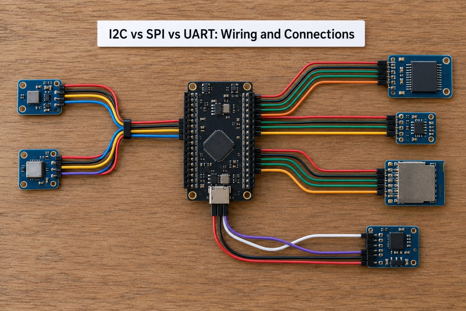
On wire count, I2C wins decisively for many devices and UART wins for exactly two. SPI sits in between and gets worse with every peripheral you add.
The wiring comparison breaks down like this. I2C needs two signal lines for the entire bus, no matter how many devices hang off it, plus a pair of pull-up resistors somewhere on the bus. SPI needs three shared lines plus one chip select per device, so three devices means six pins. UART needs two lines plus ground for each pair, and every additional device needs either a second controller port or extra hardware.
There is a subtlety with SPI and MISO. Because SPI is full-duplex, every target drives the MISO line, so chip select must gate that output. Well-behaved parts do this internally. Sloppy ones do not, and two devices that both drive MISO while chip select is high will corrupt the bus. This shows up when you hot-plug a module or leave a select line floating.
Board routing follows from the same three facts. I2C and SPI are short on-board signals, so length matching barely matters, but keep the I2C pull-ups close to the controller to minimise the exposed stub. UART is the one you might actually run off-board, and there the ground reference and cable quality do more for reliability than the baud rate does.
Signal voltage is the other wiring detail that bites. A 3.3 V controller will usually damage a 5 V target, and most breakout boards ship with both a 3.3 V and a 5 V regulator but only one set of level shifting, so check the silkscreen before wiring anything.
I2C vs SPI vs UART: Speed and Data Transfer
Is I2C faster than UART? Sometimes, and it depends which speed mode you configure. I2C in standard mode runs at 100 kHz, which is slower than a typical 115200 bps UART. I2C in fast mode at 400 kHz beats most debug UARTs, and fast-plus at 1 MHz leaves them far behind. Compare I2C against a 3 Mbps UART link and the answer flips back the other way.
The honest answer is that UART speed is set by the two devices, I2C speed is set by the slowest target on the bus, and SPI speed is set by the controller. That is why raw comparisons mislead.
| Protocol | Spec modes | Realistic sustained throughput | What limits it |
|---|---|---|---|
| I2C | 100 kHz standard, 400 kHz fast, 1 MHz fast-plus, 3.4 MHz high-speed | Roughly 80% of clock rate after address, register and ACK overhead | Pull-up rise time, bus capacitance, the slowest target |
| SPI | Controller clock, commonly 1 to 100+ MHz | Close to the clock rate; overhead is near zero | Controller max frequency and target max frequency |
| UART | 9600 bps upward, 115200 and 921600 common, 3 Mbps on faster parts | Roughly 80% of the baud rate, since 8N1 frames 10 bits per byte | Baud agreement, cable length, noise, software buffer depth |
Latency behaves differently from throughput. A UART byte takes a full millisecond at 9600 baud no matter how fast your CPU is, so debug consoles feel sluggish at low rates for a purely electrical reason. SPI transfers complete in a handful of microseconds, which is why it suits frame buffers and high-rate sampling, and why an SPI target that is not ready can still return promptly.
On a bit-banging footnote, because it comes up constantly: driving I2C or SPI from software instead of a hardware peripheral works, but it is dramatically slower. A forum thread on a CH32V003 driving a U8x8 display reported roughly 3 frames per second bit-banged, visibly too slow for an interactive interface. Treat bit-banging as a fallback when the hardware peripherals are already occupied, and budget the CPU time before you commit to it.
I2C vs SPI vs UART: Addressing Multiple Devices
I2C addresses devices in software, SPI selects them in hardware, and UART does not address at all. That difference shapes the whole layout of a board.
On a 7-bit I2C bus you get 128 address slots, and a handful are reserved by convention, so roughly 126 usable addresses. Every transaction begins with the address byte, which means the same two wires can serve a temperature sensor, an EEPROM, a real-time clock and an I/O expander without another pin. The trouble arrives when two identical breakout boards sit on the same bus with the same factory address, which is the classic I2C address conflict, and the usual answers are an I2C multiplexer such as the TCA9548A or a jumper to re-address the sensor.
Ten-bit addressing exists in the specification for exactly this scaling problem. It gives 1024 addresses, though support across controllers and targets is patchy, and mixing 7-bit and 10-bit devices on one bus is not something to rely on in a design that has to work first time.
SPI does the opposite. It has no address byte at all, so selection happens by driving a chip select line low. Adding a target is a GPIO, a wire in your schematic and a trace on the board, and that cost is the limit. Shift registers and expanders exist precisely to push chip select out to a chain instead of consuming controller pins.
UART has no addressing, which means two devices is the natural ceiling. If you need more, the options are a second UART port, a multiplexer, a UART-to-I2C bridge such as the SC16IS740, or a differential multi-drop arrangement with RS-485, where each device listens for its own command. Every one of those is added hardware and added firmware, which is why UART rarely scales past one or two peripherals.
I2C vs SPI vs UART: Distance, Noise, and Reliability
Practitioners quote three working limits: about 15 m for UART at TTL levels, about 1 m for I2C, and very short on-board runs for SPI. Those numbers come from forum consensus rather than a specification, and they hold up in practice.
I2C is the most fragile over distance. Open-drain signalling with resistive pull-ups means the signal weakens as capacitance grows, so every extra centimetre of cable slows the rising edge until timing fails. Intermittent NACKs that appear on the bench but vanish on the bench with the cable coiled are almost always a pull-up or capacitance problem. If you need more than a metre, use a differential I2C extender rather than a longer ribbon.
SPI is designed to stay on the board. The signals are strong, unidirectional and clocked, so it tolerates short traces very well, but it has no noise immunity, no error detection and no defined maximum length. A card-edge connector carrying SPI will pick up interference in ways I2C does not, because I2C at least degrades predictably.
UART is the most tolerant of a real cable, partly because the receiver only needs to resolve levels, not sample against a clock edge. It becomes unreliable without a common ground or near a noisy motor or relay. Once you push past its comfortable range, the fix is a transceiver: RS-232 for point-to-point over about 15 m, and RS-485 for longer runs or multiple drops, because the differential receiver rejects common-mode noise that would wreck a TTL link.
Grounding does more for reliability than any protocol choice. A shared ground reference, a solid ground plane and short return paths fix problems that people try to solve by lowering the baud rate.
I2C vs SPI vs UART: Advantages and Disadvantages
I2C keeps the pin count at two no matter how many devices you add, has built-in device addressing, and works with almost every small sensor and memory part on the market. The costs are a hard speed ceiling, a dependence on correctly sized pull-up resistors, a bus capacitance limit, half-duplex operation, and address conflicts that need external hardware to solve.
SPI is the fastest of the three and has essentially no protocol overhead, with both directions usable at once and a simple, well-documented mode scheme. The costs are a growing chip select pin per device, a mode parameter that must match the target exactly, no built-in addressing or error detection, and a design that does not leave the board gracefully.
UART is the simplest to wire and the cheapest to implement, needs no clock, tolerates cable length better than the other two, and is the interface every microcontroller exposes for debugging. The costs are no addressing, no multi-drop support, framing overhead on every byte, and complete dependence on both ends agreeing on settings, with a mismatch producing garbage rather than an error.
Power deserves its own line. All three leave the target in control of the clock or idle line, so quiescent current differences between protocols are usually smaller than the difference between the peripherals you attach. In a battery-powered design, the sensor and any radio dominate the budget, and the interface choice matters for power mainly through how long you can leave the bus idle or how often you have to wake the controller to poll a device. A polled UART sensor and a polled I2C sensor cost roughly the same; a radio streaming over SPI or UART costs the same either way.
Common failure modes, and how to debug them
Most embedded communication bugs are not exotic. They are one of a short list of things, and recognising them by name saves a lot of time.
- I2C NACK storm. Every read returns a not-acknowledge. Usually a wrong address, a missing pull-up, a target held in reset, or a device running at 5 V against a 3.3 V controller. Check the address from the datasheet first, then the pull-up value, then the logic levels.
- I2C address conflict. Two modules with the same factory address on one bus. The bus works with either module fitted and fails with both. The fix is a multiplexer or a re-address jumper.
- SPI data reads back as noise. The mode is wrong. Nothing errors, the bytes are just wrong, which makes this the most confusing of the three. Confirm CPOL and CPHA against the target datasheet.
- UART garbage characters. Baud rate mismatch between the two ends, or RX and TX not crossed. Garbage that is mostly readable points at baud rate; complete silence points at wiring or a missing common ground.
- UART bus contention. Two devices driving the same RX line at once, or the controller’s TX tied directly to its own RX. This damages drivers and shows up as intermittent corruption that disappears when the second device is unplugged.
- SPI MISO contention. A target that does not gate its output with chip select, so two of them fight on the line when select is high.
The fastest habit that helps on all three: bring the logic analyser out. A few dollars of one turns an I2C bus that mysteriously NACKs into a visible address byte, and a UART stream of garbage into a visible baud rate mismatch. Guessing costs far more.
The same sensor read, in all three protocols
Reading one register from one device shows the difference in overhead more clearly than any table. Here is the same task in Arduino-style C, first over I2C, then over SPI, then over UART.
I2C — the device address and register both go into the same byte stream:
#include <Wire.h>
void readSensor() {
  Wire.beginTransmission(0x76);      // device address
  Wire.write(0x00);                 // register pointer
  Wire.endTransmission(false);      // repeated start, no stop
  uint8_t data = Wire.requestFrom(0x76, 1); // request 1 byte
  if (data == 1) { value = Wire.read(); }
}
SPI — a hardware chip select, a register write, then a read burst:
#include <SPI.h>
void readSensor() {
  digitalWrite(SS, LOW);            // dedicated chip select pin
  SPI.transfer(0x00);               // register pointer
  value = SPI.transfer(0x00);       // clock one byte out
  digitalWrite(SS, HIGH);
}
UART — no addressing, so the device has to be told what to do and the answer arrives as a framed string:
#include <HardwareSerial.h>
void readSensor() {
  Serial1.begin(9600, SERIAL_8N1);  // baud, framing
  Serial1.print("rn");             // read register command
  delay(20);                        // wait for the reply
  if (Serial1.available()) {
    value = Serial1.parseFloat();
  }
}
Count the differences. I2C spends a byte on the address and a byte on every register pointer, on a bus shared with everything else. SPI spends nothing but a chip select that costs a pin. UART spends nothing on addressing but needs a command parser and cannot add a second device to the same port.
Which Should You Choose?
Pick I2C when you have many small devices and few pins to spare, pick SPI when throughput matters and the devices sit on the same board, and pick UART for a point-to-point link, a debug console or a module that speaks serial.
| Project | Use | Why |
|---|---|---|
| Weather station: temperature, humidity, pressure, RTC | I2C | Four small slow devices, two wires total |
| Data logger writing to a microSD card | SPI | Block transfers need throughput; cards do not need addressing |
| GPS module feeding a character display | UART for GPS, SPI or I2C for the display | Each part is used where it is strongest |
| Motion control board with accelerometer, flash and a display | SPI | Sampling and frame rates, all on one board |
| Debug console and a firmware update header | UART | Point-to-point, no addressing needed |
| Two microcontrollers sharing sensor data | SPI or UART | SPI for volume on a shared board, UART for the simplest link |
| Battery-powered wearable | I2C | Two pins leave more GPIO for sensors, and sleep current dominates |
| Sensor node with a radio more than 10 m away | UART with RS-485, or a wireless module | TTL UART is marginal past 15 m in a noisy enclosure |
Before you commit, run four checks. List your devices and their data rates, since anything above a few hundred kilobits per second or any frame buffer should push you to SPI. Count the pins you have against chip selects and UART ports, because that is the constraint that actually fails builds. Measure the distance and the environment, since noise and cable length rule I2C out faster than speed does. Then check peripheral availability, because a sensor that only exists in an I2C version will decide the question for you.
Most real boards use all three at once, and that is not over-engineering. A sensor node with an I2C temperature sensor, an SPI flash part for logging and a UART for a debug header is entirely normal, because each interface is doing what it is good at.
Two adjacent protocols come up in the same conversations. CAN (ISO 11898) is the automotive and industrial answer when you need long cables, strong noise immunity and deterministic multi-drop messaging, and it is the right choice the moment I2C’s 1 m limit or UART’s lack of arbitration becomes the problem. 1-Wire is the opposite extreme: one data line and a ground, with addressing and power sharing, used for temperature probes and memory. Both sit in the same category of thought: the bus you pick is a set of constraints on wire count, speed and distance, and the three here are simply the most common points on that trade-off.
Frequently Asked Questions
Can I2C, SPI, and UART be used at the same time?
Yes, most modern microcontrollers provide separate peripheral blocks for all three, so a single board can run an I2C sensor, an SPI flash part and a UART debug console simultaneously. They coexist as long as pin mappings do not overlap, logic voltage levels match, and each driver owns its pins. Watch for shared interrupt lines and for the fact that some low-pin-count parts multiplex the same pins across peripherals.
Which is faster, SPI or I2C?
SPI is usually faster for short direct transfers. It has a dedicated clock, separate data lines running in both directions at once, and almost no framing overhead, so it commonly runs at tens of MHz. I2C tops out at 100 kHz standard, 400 kHz fast, 1 MHz fast-plus and 3.4 MHz high-speed, and the slowest target on the bus sets the rate for everyone.
Does UART need a clock wire?
No clock wire at all. Both devices independently agree on a baud rate and stay in sync using framing, where each byte carries a start bit, data bits, an optional parity bit and a stop bit. The catch is that the agreement is assumed rather than negotiated, so if the two ends are configured differently you get garbled data rather than an error message. Add a common ground and cross TX to RX.
Why do I2C wires need pull-up resistors?
I2C uses open-drain signalling, so no device ever drives SDA or SCL high. Devices pull the line low to send a zero and release it to send a one, and external pull-up resistors create that high state. The resistor value also sets the rise time against the bus capacitance, so too weak a pull-up on a long or crowded bus causes slow edges, timing failures and intermittent NACKs.
Is I2C faster than UART?
It depends on the speeds you configure. I2C in standard mode at 100 kHz is slower than a UART running at 115200 bps, while I2C in fast mode at 400 kHz or fast-plus at 1 MHz is faster than most debug UART links. A UART at 3 Mbps outruns any standard I2C mode. I2C also spends bit time on addresses, register pointers and acknowledgements, so useful throughput runs below the clock rate.
How many devices can you connect to one I2C bus?
A 7-bit I2C bus provides 128 address slots, of which a few are reserved, leaving about 126 usable addresses. The practical limit is usually lower because you also have to keep total bus capacitance under 400 pF and fit the rise time budget. Reserved addresses, identical factory addresses on multiple modules and 10-bit addressing support all affect the real number you can attach.
Conclusion
Before you wire anything, check four things: which peripherals the module actually supports and their data rates, how many pins the bus topology needs, the distance and noise between the two ends, and the address or chip select budget. I2C is the answer when the answer is many small devices on two wires, SPI when it is volume over a few centimetres, and UART when it is one device talking to one device with no addressing required. Implement the simplest of those that meets the requirement, then check the datasheets for the details the datasheet alone can tell you, such as the pull-up value, the SPI mode and the baud rate.