A pick and place machine is the automated arm that builds a printed circuit board. It picks surface-mount components out of tape-and-reel feeders, checks each one with a camera, and sets it down on the correct pad of a board that already has solder paste on it. Placement is the physical step in surface mount assembly, and where the board is actually assembled, one part at a time.
Most people meet the machine before they understand it. A video of a nozzle zipping across a green board at 30,000 components an hour looks like magic until you break it into feed, align, pick, move, place. That’s what this guide does, piece by piece, and then covers the parts that trip up beginners: what accuracy actually means, how to set a board up, and what to check when parts land crooked or don’t get picked at all.
Table of Contents
- What Is a Pick and Place Machine?
- What kinds of components can it handle?
- How Does a Pick and Place Machine Work?
- What Are the Main Parts of a Pick and Place Machine?
- What Do Placement Accuracy and Speed Mean?
- Which Types of Pick and Place Machines Are Used?
- How Are Pick and Place Machines Set Up for a PCB?
- What Placement Head and Feeder Options Should Beginners Know?
- Why Does the Machine Need Vision and Calibration?
- What Are the Most Common Pick and Place Problems?
- What Should You Know Before Buying or Using One?
- Frequently Asked Questions
- Do pick and place machines solder components onto the PCB?
- How fast can a pick and place machine place components?
- What placement accuracy is needed for hobby PCB assembly?
- Can a pick and place machine rotate components to the correct orientation?
- Is a desktop pick and place machine suitable for beginners?
- Conclusion
What Is a Pick and Place Machine?
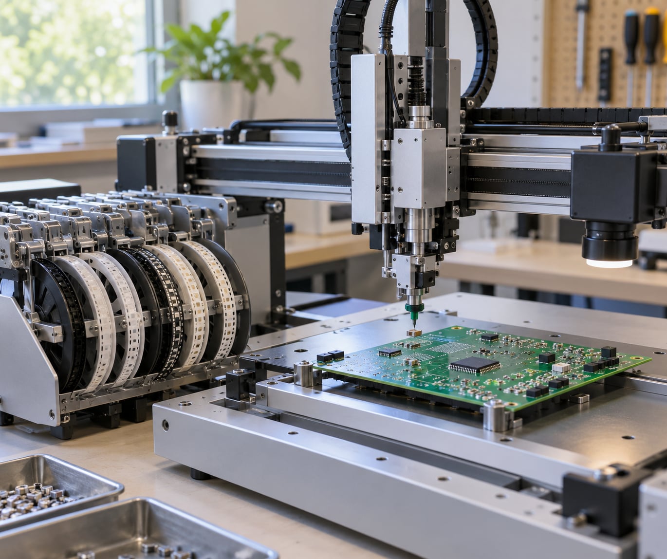
A pick and place machine, also called a placement machine or mounter, is an automated assembly machine that picks electronic components from feeders and places them onto precise locations on a printed circuit board. It feeds parts to a placement head, aligns them with machine vision, picks them with vacuum nozzles, and sets them down on solder-pasted pads, often at thousands of components per hour.
Manual placement means a person holds tweezers over a board. A pick and place machine does the same motion with calibrated axes and a camera instead of eyes, which is why it can repeat the same placement a hundred thousand times without drifting. It does not solder anything. The parts land on paste, and a reflow oven later melts the paste to lock them down.
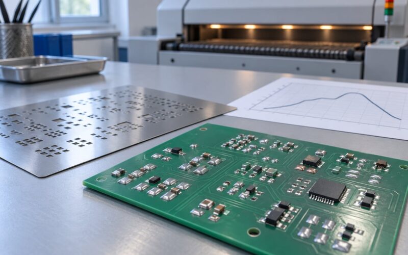
On a full SMT line, placement is the third stage: solder paste is printed through a stencil, components are placed, the board goes through reflow, and then it gets inspected with AOI and X-ray. Placement sits in the middle because it needs paste already down and inspection waiting behind it.
What kinds of components can it handle?
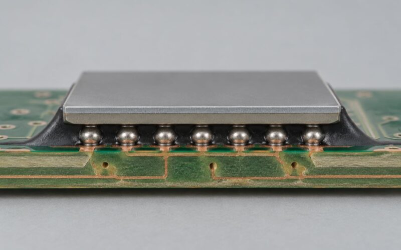
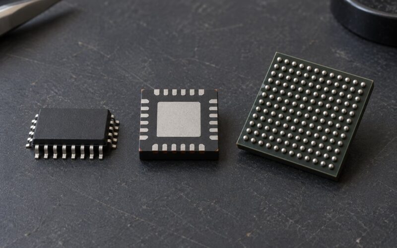
Standard chip passives such as 0402, 0201 and 01005 resistors and capacitors, plus SOIC, SOT, QFN, BGA and uBGA packages. Each package sets the requirements for nozzle bore, vacuum and camera resolution. The smallest parts on a board decide which machine you need, not the average part size.
How Does a Pick and Place Machine Work?
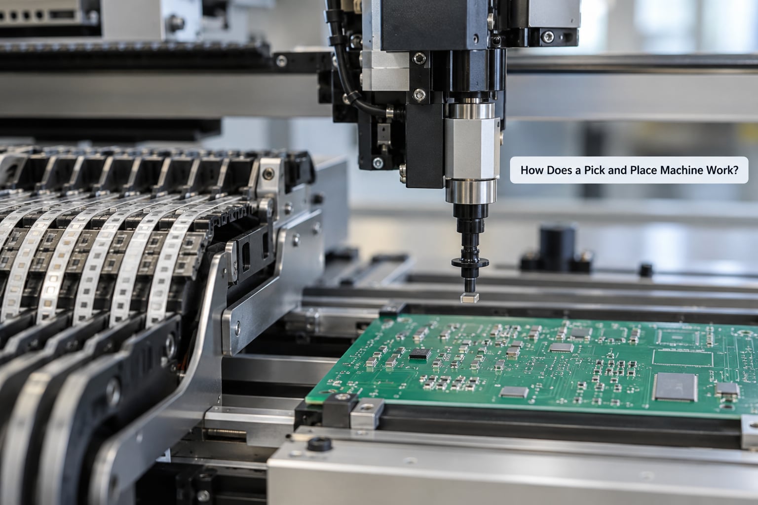
Every component goes through the same eight-step cycle. The machine repeats it for each item in the bill of materials and logs the result.
| Stage | What happens | Why it matters |
|---|---|---|
| Board load | The board indexes into the machine on rails or a conveyor and is held down by fixtures. | Fixes the board physically so every coordinate means the same thing on every run. |
| Fiducial read | Cameras find global and local fiducial marks printed on the board. | Establishes real board position instead of the nominal one from the CAD file. |
| Feeder advance | A tape-and-reel feeder indexes forward one pocket. | Presents the next component at a fixed pick point. |
| Vision align | The camera measures the part’s actual offset and rotation, and the board’s own offset and rotation. | Compensates for feeder mis-index, board expansion and part skew in the tape. |
| Pick | A vacuum nozzle descends, contacts the component and lifts it. | Vacuum level and nozzle bore have to match the part mass and size. |
| Transfer | The gantry moves to the board position, often with a second camera check in flight. | Confirms the part is still held and measures the final offset before release. |
| Place | The nozzle lowers to a programmed Z height and releases. | Too high and the part floats or bounces; too low and it gouges the paste. |
| Log and repeat | The machine records the placement, then advances to the next component. | The log is the traceability record used to trace a defect back to a specific placement. |
That table is the whole machine in miniature. Everything else, the frame, the software, the feeder bank, exists to run those eight steps quickly and repeatably.
What Are the Main Parts of a Pick and Place Machine?
A placement machine has six subsystems that cooperate, and if you can name them you can read a spec sheet or a service manual without guessing.
Frame and gantry. The frame holds everything rigid. The gantry carries the placement head on X, Y and Z axes, driven by ball screws or linear motors. Frame rigidity sets the accuracy ceiling: a frame that flexes under a fast head cannot place accurately no matter what the specification says.
Feeder system. Feeders hold components in tape-and-reel, cut tape, trays or bulk and index them to a fixed pick point. Feeder capacity, measured in slots, decides how many different part numbers a machine can hold without a changeover.
Component tape and reels. Components ship in continuous tape with a moulded pocket per part and a cover tape over the top. The pockets keep parts in one plane and at a fixed pitch, which is what makes machine vision able to measure them.
Placement head and nozzles. The head is the moving carriage. Nozzles are small vacuum tools that touch the component, and a turret head carries several at once on a rotating disc so it can pick several parts per pass. Nozzle bore, vacuum force and Z height are set per component type.
Vision system. Cameras look down at the board and at the part on the nozzle. They measure fiducials, part offset, part rotation and nozzle-to-nozzle error, then feed corrections back to the motion system.
Controller and software. The controller turns the placement file into motion. Software also handles the feeder map, board definition, error codes, placement logs and the calibration routines. This is where beginners are often disappointed: the mechanics are straightforward, the interface is where the time goes.
Safety features sit on top of all of that: light curtains and interlocks around the motion envelope, an emergency stop, and nozzle-contact and vacuum sensors that stop the head before it crashes into a fixture.
What Do Placement Accuracy and Speed Mean?
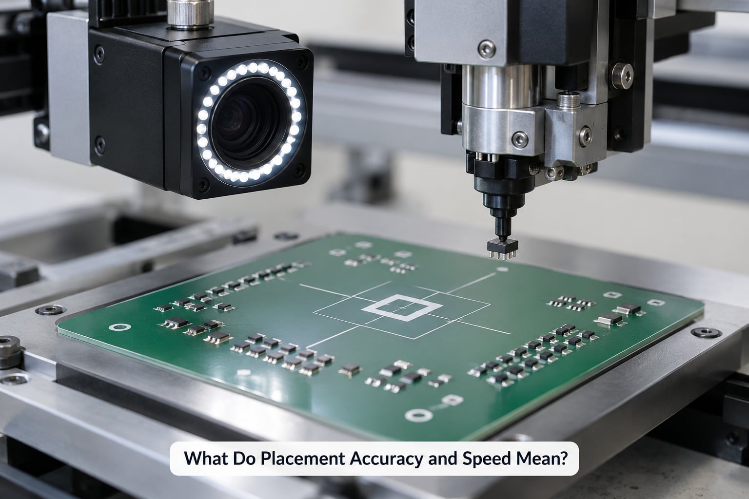
Placement accuracy is how close the component lands to the position the design intended, in micrometres. Speed is components per hour. They are different measurements, and a machine can have an excellent number for one and a poor number for the other.
| Term | What it measures | What it actually means for your board |
|---|---|---|
| Placement accuracy | Distance between the true component position and the commanded position, usually quoted at 3-sigma. | Check this spec at your smallest package, not on the datasheet headline. |
| Repeatability | How tightly the machine returns to the same point over many cycles. | Repeatability is what protects a fine-pitch pad from bridging, and it matters more than absolute accuracy. |
| 3-sigma | A statistical band that should contain about 99.7 percent of measurements. | Most accuracy specs are 3-sigma figures, so the tail of bad placements sits outside the headline number. |
| Cpk | How well a process fits inside its tolerance window, with 1.33 often used as a target. | A Cpk quoted at 1.0 is not the same process capability as one quoted at 1.33. Ask which was measured. |
| CPH (components per hour) | Placement rate, usually quoted with no component or at a specific part size. | Real rate drops on small parts, dense boards and changeovers. A headline CPH is a best case. |
| Cycle time | Seconds for one placement from pick to release. | Multiply by part count to estimate build time before any feeder stops or rejects. |
| First pass yield | Share of boards that pass inspection without rework. | The number that decides whether the machine was worth it. Placement error drives most of it. |
Two traps here. First, a machine rated for 40,000 CPH on 0805 parts may crawl on 0201s, because every vision check and vacuum confirmation costs time and small parts force slower axis motion. Second, specs are frequently quoted at a large package and a small Cpk. Ask what package size and what Cpk the number refers to.
IPC-9850 is the standard that defines how placement machine accuracy and performance are measured, and why vendors quote against it. It sets the conditions under which a machine is measured, which is why two machines with the same quoted accuracy can behave very differently on the same board. ISO 9283 covers positioning performance of machine tools and shows up in the same spec sheets.
Which Types of Pick and Place Machines Are Used?
Machines fall into tiers by how much of the cycle is automated and how fast they run. The right tier is set by volume and mix, not by ambition.
| Type | Typical use | What you give up |
|---|---|---|
| Manual placement | Prototype rework, one-off boards, bench work. | Speed and consistency. A person with tweezers places a few dozen parts an hour. |
| Manual-assisted feeders | Small shops moving from hand placement to feeders and vacuum. | The human still positions the head, so boards must be simple and well marked. |
| Hobby and desktop | Prototype and small batch work at a bench, with a small camera, arm and vacuum pump. | Board size, component range and throughput. Good for learning, wrong for production. |
| Benchtop | Prototype and low-volume assembly in a small production cell, often dual-side. | Feeder capacity and fine-pitch capability versus factory machines. |
| Turret | Mid-speed production where many nozzles work in parallel on a rotating head. | Flexibility. A turret is optimised for a narrower component range than a gantry. |
| Gantry | High-mix production with many part numbers and a large feeder bank. | Raw speed versus a high-speed machine, in exchange for flexibility and accuracy. |
| High-speed | High-volume, low-mix runs of a proven board. | Setup flexibility. These are built to repeat one job extremely fast. |
Desktop and benchtop machines get discussed on a separate track from factory machines, and for good reason. A desktop unit with a camera, a small arm and a vacuum pump is a teaching and prototyping tool. Factory equipment is a capital decision with feeder banks, spares and support contracts attached.
How Are Pick and Place Machines Set Up for a PCB?
Setup is the part beginners underestimate. The order below is the order operators actually work in.
Import the CAD data. The Gerber or ODB++ files give pad coordinates and the pick-and-place or centroid file gives the component list. The bill of materials (BOM) links part numbers to those coordinates. If the centroid file and the CAD data disagree, stop and fix that before touching the machine.
Define the packages. For each part number you tell the software the package type, the tape pocket geometry, the rotation correction and the placement Z height. Small parts, polarized parts and fine-pitch parts each need their own entry.
Load the feeders. Insert the tape and reels, assign each reel to a feeder slot, and record the slot in the software’s feeder map. Get this wrong and the machine will happily pick part A when the board wants part B.
Create the board. Load the board file, set the origin, confirm the panelization rails if the board is on a panel, and check that the fiducial marks exist on the artwork. No fiducials means no correction and no reliable placement.
Check polarity and rotation. Verify the pin-one marker on every polarized part and the rotation of every fine-pitch device. A 90 degree error on a QFN is not visible until the board fails.
Calibrate. Run the camera calibration so the software knows exactly where the machine is, then verify nozzle offsets. Calibration checks the machine against itself; the fiducial system checks the machine against the board.
Run a test placement. Place a handful of parts, or a full first board, and inspect them under magnification before running the job. Treat the first board after every changeover as a test board. Operators learn this the hard way, and then keep doing it.
What Placement Head and Feeder Options Should Beginners Know?
The head and the feeder are where flexibility lives. This is the vocabulary you need to read a machine’s capability list.
Vacuum nozzles. A single nozzle takes one part at a time. Multiple nozzles let the head pick several parts per pass, which is the main reason a turret or a multi-nozzle gantry outperforms a single-nozzle machine at the same nominal speed. Nozzle selection is per component: small bore for 01005, larger bore for a big BGA.
Single-head and turret systems. A single-head machine carries one tool and is simpler and more flexible. A turret head rotates through a fixed set of nozzles, which is faster but limits the component range the machine can be optimised for.
Tape-and-reel feeders. The production default. They hold hundreds or thousands of parts, index one pocket at a time and keep every part in the same plane. Carousel and belt feeders use the same tape.
Cut-tape feeders. For prototypes and small quantities. You cut a short length of tape, drop it in, and the machine indexes by hand through the remaining pockets. Low capacity, but no reel handling.
Trays and bulk feeders. JEDEC trays suit larger parts and BGA devices. Bulk or bowl feeders suit loose, unbagged parts and are used for high-volume runs of one part number.
Nozzle changer. On machines that handle a wide range of packages, an automatic changer swaps nozzles between placements. It is the difference between a machine that can run your whole BOM and one that needs a manual intervention halfway through.
Why Does the Machine Need Vision and Calibration?
Vision is what converts a coordinate list into accurate placements. The machine was told where the part should be, not where it is.
Fiducial detection. A fiducial is a small copper mark printed on the board specifically for the machine to see, usually a solid circle or a cross. Global fiducials set the board’s overall position. Local fiducials, placed near dense or fine-pitch areas, set the position of that region. Reading both lets the machine correct a board that has expanded, bowed or shifted in the fixtures.
Component inspection. Before the pick, the camera measures the part’s offset and rotation from its pocket. After the pick, a second camera looks at the part on the nozzle and measures the same two values plus the nozzle’s own offset. A second machine with different nozzles can then pick the same part with a different bore and still land it correctly.
Board compensation. The correction computed from fiducials is applied to every coordinate on that board. This is why a board that flexes on the rails still gets placed accurately, and why the compensation must be re-read for every load, not once per program.
What calibration does. Calibration tells the software where the axes actually are and how the cameras map to machine coordinates. Vision cannot compensate for a miscalibrated machine, and calibration cannot compensate for a moving board. You need both, and they fail differently.
What Are the Most Common Pick and Place Problems?
Operators tend to fix these in a fixed order because it is the fastest path: nozzle first, then vacuum, then feeder, then board flatness and cleanliness, then vision. Most offset placements get recovered by cleaning the board, reprinting paste and replacing the part.
| Symptom | Likely cause | Check and fix |
|---|---|---|
| Parts thrown out or skipped | Damaged or deformed nozzle, weak vacuum, static on small parts. | Inspect the nozzle tip under magnification, check vacuum level, clean the nozzle, confirm the feeder is presenting the part. |
| Components land offset | Feeder mis-index, nozzle condition, board movement, paste printed off-centre. | Re-index or advance the feeder, recheck nozzle offset, confirm the board is held flat, verify the print. |
| Wrong rotation | Package definition rotation not applied, or a part skewed in the pocket. | Check the rotation field in the package entry, re-run vision on that part type. |
| Polarity or wrong part | Feeder map entry points to the wrong reel, or a rail stop is out of position. | Verify the feeder assignment against the BOM, then re-run the first-board check. |
| Feeder jam or misread | Tape splice, bent cover tape, pocket damage, index sensor fault. | Advance the feeder, inspect the pocket and cover tape, check the index sensor. |
| Vision misread | Poor lighting, dirty lens, camera calibration drift, low contrast pad. | Clean the lens, re-run camera calibration, check lighting and the board finish. |
| Bridging or poor joints after reflow | Placement offset on fine-pitch pads, or too much paste. | Confirm placement offset first, then check the stencil aperture ratio and the print. |
| Tombstoning on small chip parts | Uneven solder paste volume, or the part was disturbed as it was released. | Balance the paste deposit, check Z height, confirm the part seats flat before the nozzle retracts. |
Bridge and tombstone defects are worth a note. A part placed even slightly off a fine-pitch pad changes how solder wets during reflow, and the resulting bridge or lifted end cannot be fixed by retuning the oven. Most of these defects originate at placement.
What Should You Know Before Buying or Using One?
Match the machine to your hardest part, not your average part. Take the smallest package on your BOM and the largest board you build, and check the machine against both.
Component size and shape. 01005 parts and fine-pitch BGAs pull in opposite directions, and one machine rarely covers both well. 0402 and 0201 chip parts are common entry points; uBGA and fine-pitch QFN demand the highest-end vision and accuracy.
Package data. Reliable package dimensions and land patterns come from standards such as IPC-7351 for land pattern design and IPC-A-610 for acceptability, rather than from a vendor drawing. JEDEC J-STD-020 and J-STD-033 govern moisture handling, which matters for lead-free packages that must be baked before assembly.
Feeder capacity and board size. Count the distinct part numbers on your BOM and compare to feeder slots. Measure your panel, not just the bare board, if you run rails.
File support and software. Check the formats the machine accepts and how the software handles a new part type. If you cannot add a package without vendor help, every future assembly depends on that vendor.
Maintenance. Nozzles wear, feeders need cleaning, cameras need calibration and the vacuum pump needs service. Over a ten-year life, operating cost and downtime usually matter more than the purchase price. Spare nozzles and a spare feeder bank are cheap insurance.
Safety. Never reach into a moving machine. Lock out the power before changing nozzles or clearing a jam, and follow the machine’s manual and your site’s electrical safety rules.
Placement is not soldering. The machine sets parts onto paste. Reflow does the joining, and AOI and X-ray check the result. Buying a placement machine does not buy you a complete assembly line.
Frequently Asked Questions
Do pick and place machines solder components onto the PCB?
No. A pick and place machine only sets components onto the board. The board must already have solder paste printed through a stencil, and a reflow oven melts the paste to form the joints. Inspection with AOI or X-ray usually follows reflow. Some machines can be integrated into a line that also prints and reflows, but the placement head itself never solders anything.
How fast can a pick and place machine place components?
Speed depends on the machine and the parts. A turret machine handles tens of thousands of components per hour on larger parts, while a gantry trades some raw speed for flexibility. Small parts such as 0201 and 01005, dense boards and vision checks all slow the real rate well below the headline figure. Always ask for the rate at your smallest package.
What placement accuracy is needed for hobby PCB assembly?
For 0802 and 0603 parts, a benchtop or desktop machine with roughly 0.1 mm accuracy is usually enough. Fine-pitch SOIC and QFN parts need tighter alignment, typically 0.05 mm or better, and BGAs demand both fine accuracy and reliable vision. Check the accuracy spec at your smallest package and confirm the tolerance of the pads you are placing onto.
Can a pick and place machine rotate components to the correct orientation?
Yes. Rotation is set per component in the package definition, and the vision system measures the actual rotation of the part before placement so it can correct a part that sits crooked in its tape pocket. Polarized parts such as diodes, electrolytic capacitors and pin-one ICs rely on this to land correctly. Incorrect rotation usually points to a package entry error rather than a machine fault.
Is a desktop pick and place machine suitable for beginners?
For learning the process, yes. A desktop machine with a camera, a small arm and a vacuum pump lets you see every step of the cycle on a small board without a large capital commitment. It is limited by board size, feeder capacity and component range, so it suits prototypes and small batches. Moving to production volumes means a benchtop or factory machine and a proper support arrangement.
Conclusion
Pick and place machine basics come down to one loop: feed a part, look at it, pick it, look again, put it down, log it. Feeders present the component, cameras correct for where it actually is, nozzles hold it, the gantry moves it, and fiducials tell the machine where the board really sits. Everything else on the machine serves that loop.
Before you commit to a machine, take your smallest and most difficult part, find out the accuracy the machine holds at that package rather than at the headline package, and confirm your feeder slots cover the part numbers on your bill of materials. Build one board, inspect it under magnification, and only then run the job.