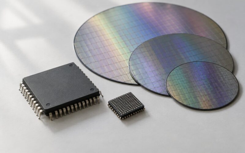
AEC-Q100 is a failure-mechanism-based stress test specification for packaged integrated circuits used in automotive electronics, published by the Automotive Electronics Council rather than a regulator. The current base document is Rev J with a J1 addendum. It tells a manufacturer how to prove a part survives 10 to 15 years of under-hood heat, humidity, vibration and static discharge at single-digit defect rates per million. It is not a certification, not a production test, and it does not approve a component for a safety role.
That last point is where a lot of confusion starts, so this guide walks the whole flow: who needs it, what the stages are, what the seven test groups actually prove, how the temperature grades work, and how to check a supplier’s claim rather than trusting a part-number suffix.
Table of Contents
- What Is AEC-Q100 Qualification?
- AEC Q100 qualification explained in under a minute
- What the Q100 designation means
- Who Needs AEC-Q100 Qualification?
- AEC-Q100 Qualification at a Glance
- How the AEC-Q100 Qualification Process Works
- Why the sample sizes are 45, 231 and 2400
- A worked example: choosing the grade from the mission profile
- What Stress Tests Are Required?
- What Do AEC-Q100 Grades and Temperatures Mean?
- Grade 1 versus Grade 2 in practice
- AEC Document Family: Q100, Q101, Q200 and Friends
- What Happens After Qualification?
- How to check a qualification claim on a datasheet
- AEC-Q100 Qualification vs Other Automotive Requirements
- Common AEC-Q100 Qualification Mistakes
- Frequently Asked Questions
- What is the AEC-Q100 qualification?
- What are the AEC-Q100 grades?
- What is the difference between AEC-Q100 Grade 1 and Grade 2?
- What is the difference between AEC-Q100 and AEC Q101?
- Does AEC-Q100 cover functional safety?
- How long does AEC-Q100 qualification take?
- How do I check if a chip is AEC-Q100 qualified?
- Conclusion: Start With the End-Use Environment
What Is AEC-Q100 Qualification?
AEC Q100 qualification explained in under a minute
The supplier defines the exact orderable part number, its grade, its package and the automotive use conditions it must survive. Samples from three independent production lots go through a defined set of accelerated stresses, grouped A through G, and every part is electrically tested before and after at room and at hot temperature. Zero failures are allowed, and the result is published as a qualification report the customer can audit.
What it is not: a certificate, a one-time lab stamp, or a statement that the part is fit for functional safety. It is a body of evidence tied to a specific part number, a specific grade and a specific set of test conditions.
What the Q100 designation means
Q stands for qualification. The number is a document index, not a quality score. Q100 covers integrated circuits. Q101 covers discrete semiconductors, Q200 covers passive components, and later documents cover power devices, LEDs, optical components, magnetic parts, multi-chip modules and AI accelerator silicon. A lower number does not mean a better part.
The council itself is a private industry consortium of automotive OEMs and semiconductor suppliers. It publishes the base document free of charge and does not inspect anyone. Compliance becomes real only when an OEM or a Customer Specific Requirement (CSR) writes it into a supply agreement, which is also the point at which it turns into something an OEM will refuse PPAP without.
The base document is freely available from aecouncil.com, and the JEDEC test methods it references are equally public. Nothing here is hidden; the difficulty is that the document is written as a framework and the actual test plan is negotiated device by device.
Who Needs AEC-Q100 Qualification?
Responsibility sits with the semiconductor manufacturer. The supplier runs the qualification, signs the report and stands behind the part number for the life of the program. An OEM or a Tier 1 buyer then audits that evidence during sourcing, sample approval and PPAP rather than running its own stress tests on incoming silicon.
For a fabless company the work is spread across three parties, and this is where programs slip. The foundry owns the wafer process and controls what generic data it will share, the IP vendor supplies the hardened block and often its own qualification report at the block level, and the assembly and test partner owns the package, the moisture handling and the final test flow. The fabless company assembles those pieces into one qualified part number, and the customer audits the assembly rather than the individual contributions.
Design engineers, sourcing staff and quality teams all inherit the requirement without writing the test plan. The practical point: when a supplier answers a question about qualification, ask for the orderable part number and the revision of the report, not the product family name.
AEC-Q100 Qualification at a Glance
| Stage | Purpose | Evidence produced | Decision it supports |
|---|---|---|---|
| Device and use definition | Fix the orderable part number, grade, package and mission profile | Device definition record, sample plan | Which grade and which test set apply |
| Sample and lot selection | Build the statistical basis for the results | Lot traceability, sample size calculation | Whether the confidence level is acceptable |
| Stress testing | Accelerate the failure mechanisms the vehicle environment will trigger | Test records per sample group | Which mechanisms are covered or left exposed |
| Electrical verification | Prove the part still performs at room and hot after stressing | Pre- and post-test parametric data | Whether parameters drifted beyond the data sheet limits |
| Final qualification report | Publish results against the planned matrix | Product Qualification Report (PQR) | Acceptance at PPAP and sample approval |
| Production controls | Keep the qualified configuration unchanged and watch the field | PCN records, DPPM and FIT monitoring, longevity plan | Whether requalification or a second source is needed |
How the AEC-Q100 Qualification Process Works
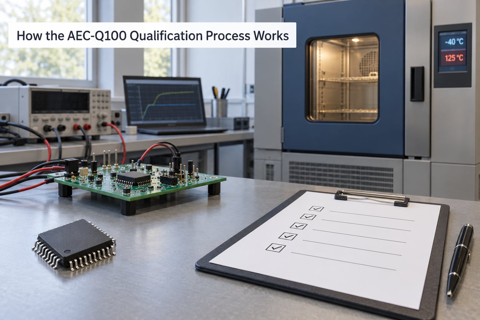
The order of operations matters more than the list itself, because each stage constrains the next. A device is first defined, not qualified: the supplier writes down the exact orderable part number, the die and package combination, the intended grade and the environmental conditions the customer expects. The test matrix is then built against that definition, which is why a change to package or grade later in the program is a serious event rather than a clerical update.
Sample and lot selection. Parts come from three independent production lots. That rule exists so a result cannot be carried by one unusually clean wafer run, and it is the first thing an auditor checks in the report.
Preconditioning. Samples are baked to drive residual moisture out of the package and mould compound. J-STD-020 governs the handling of moisture-sensitive devices, and a customer that has watched a part fail only after a second reflow knows why this step is not optional.
Stress. The matrix runs groups A through G. Samples are split so that no unit is asked to survive stress it was never meant to combine, and the assignment of units to tests is written down before the run starts.
Post-stress read-out. Every stressed part is tested again. The commercial equivalent of the same die is often only post-tested at room temperature, while the Q100 part is pre- and post-tested at both room and hot temperature. A TI engineer described exactly that difference on the vendor support forum, and added that build materials and even some specifications can differ between the two variants of the same device.
Reporting. The result is a Product Qualification Report. The useful parts are the sample size per test, the actual conditions used, the lots used, and the pre- and post-parametric limits. A report that lists test names without conditions is not something you can audit.
Why the sample sizes are 45, 231 and 2400
The numbers are not arbitrary. Sample size comes from the reliability demonstration equation n = ln(1-C) / ln(R), where R is the reliability being demonstrated and C is the confidence. At R99 with C90, a single group of 77 parts is enough. Split across three lots that is 231 parts. The early life failure rate test needs a much larger population, so it uses 800 parts per group, which is 2400 across three lots.
| Test context | Parts per group | Lots | Total parts |
|---|---|---|---|
| Typical stress and group testing | 77 | 3 | 231 |
| Early life failure rate | 800 | 3 | 2400 |
| Burn-in and screening | Defined by the plan | 3 | Plan dependent |
The confidence level matters as much as the sample count. A test that passes with 90% confidence leaves a wider uncertainty band than one demonstrated at 99%, and a supplier quoting a large sample size without naming the confidence level has told you very little. Zero failures are permitted, so a single reject sends the affected group back rather than being averaged into a passing result.
A worked example: choosing the grade from the mission profile
Take a battery management system front end parked in the engine bay. Its stated ambient environment is -40 to +105 °C at the ECU level, with a local hot spot near the power stage, vibration from the road surface and high humidity. Start from the environment, not from the datasheet.
Ambient -40 to +105 °C points at Grade 2. But junction temperature is what the silicon actually sees, and junction temperature is ambient plus the rise inside the package at worst-case dissipation. If that calculation crosses 125 °C, the honest answer is that Grade 2 does not fit the installation and the design needs either more thermal headroom or a Grade 1 part. Choosing the part first and reading the temperature limits afterwards is how an ECU ends up qualified for a condition it will never see in production.
Everything else follows from that same mission profile. A part that never leaves the cabin does not need a Grade 1 stress plan, and a part that does see the hood needs humidity and temperature cycling results in the report before a reviewer will accept it.
What Stress Tests Are Required?
AEC-Q100 groups the tests A through G. The exact set is chosen per device, package, grade and customer requirement, so treat the list below as the framework rather than a universal bill of materials. A converter does not carry the same data retention test as an EEPROM.
| Group | What it covers | Representative tests and JEDEC references | Failure mechanism addressed |
|---|---|---|---|
| A | Accelerated environment stress | Temperature cycling (JESD22-A104), power temperature cycling, high temperature storage life (JESD22-A108), temperature humidity bias (JESD22-A101), highly accelerated stress test (JESD22-A110) and its autoclave equivalent | Package delamination, die attach fatigue, moisture ingress, corrosion of bond and metallisation |
| B | Accelerated lifetime simulation | High temperature operating life, early life failure rate, active burn-in | Electromigration, stress migration, dielectric breakdown, weak-bond early failures |
| C | Package assembly integrity | Wire bond shear and pull, solder ball shear, solderability, visual and X-ray inspection | Interconnect fatigue and weak solder or bond joints under temperature cycling |
| D | Die fabrication reliability | Time dependent dielectric breakdown, hot carrier injection, bias temperature instability, negative bias temperature instability, positive bias temperature instability | Oxide and interconnect degradation that shows up as drift rather than immediate failure |
| E | Electrical verification | Parametric tests at room and hot temperature, functional patterns, threshold and leakage limits | Any shift outside the data sheet, in either direction |
| F | Defect screening | Electrical overstress screening, static discharge human body model and charged device model, latch-up, soft error rate | Handling damage, latent ESD damage, single-event upsets |
| G | Cavity package integrity | Fine leak and gross leak tests, hermeticity, die attach and substrate integrity where a cavity package is used | Moisture and gas ingress into a sealed cavity |
Group A is the one engineers argue about most, because the choices are not equivalent. A highly accelerated stress test is faster but harsher and not always required; a temperature humidity bias run takes longer and drives a different moisture mechanism. If a report shows one substituted for the other, ask why. The acceleration model has to match the failure mechanism you are trying to expose, otherwise a fast test simply produces a fast, meaningless result.
One warning about secondary sources: the lettering of groups B through G is relabelled differently by different websites. Some pages run environment, lifetime, package, die, electrical, screening and cavity in a different order from the base document. Use the AEC base document as the reference whenever two explanations disagree.
What Do AEC-Q100 Grades and Temperatures Mean?
A grade states an ambient operating temperature range and the stress severity that follows from it. It is not a quality ranking, and Grade 3 is not a worse part than Grade 0. It is a different claim about where the part is allowed to live.
| Grade | Ambient range | Typical vehicle location | Example ECUs |
|---|---|---|---|
| Grade 0 | -40 °C to +150 °C | Engine bay, exhaust and transmission surroundings | Engine controller, transmission control, ignition |
| Grade 1 | -40 °C to +125 °C | Under the hood, battery pack and tow areas | Body controller, powertrain modules, battery management |
| Grade 2 | -40 °C to +105 °C | Cabin and body with a sealed ECU in a hot region | Body modules, gateways, HVAC, seat control |
| Grade 3 | -40 °C to +85 °C | Cabin interior only | Infotainment, cluster, seat electronics, HVAC controls |
Two details catch people out. First, the range is ambient, not junction. A Grade 1 part in an under-hood ECU will see a junction temperature above 125 °C in normal operation, which is expected and allowed as long as the part is rated for it and the package can move the heat. Second, the AEC-Q200 passive scale runs colder at the top end than the Q100 scale, so a Grade 0 passive and a Grade 0 IC are not the same number.
Grade 1 versus Grade 2 in practice
| Condition | Grade 1 | Grade 2 |
|---|---|---|
| Ambient range | -40 °C to +125 °C | -40 °C to +105 °C |
| HTOL junction target | 125 °C | 105 °C |
| Temperature cycling extremes | -40 °C to +125 °C | -40 °C to +105 °C |
| Typical placement | Under the hood | Cabin or body |
| Selection driver | Mission profile demands it | Mission profile does not demand more |
The difference is a hotter stress, not a better part. Specifying Grade 1 where the mission profile only needs Grade 2 adds cost and longer test time for reliability you were not asking for, and specifying Grade 2 for an under-hood location leaves the part stressed below the condition it will actually see. The grade is an output of the end-use environment, never a line item to be maximised.
AEC Document Family: Q100, Q101, Q200 and Friends
When someone asks which AEC document applies, the answer is almost always determined by the component class.
| Document | Component class | Typical parts |
|---|---|---|
| AEC-Q100 | Integrated circuits | MCUs, analog and mixed signal, power management ICs, memory, interface ICs |
| AEC-Q101 | Discrete semiconductors | Diodes, transistors, thyristors, MOSFETs, rectifiers |
| AEC-Q200 | Passive components | Resistors, capacitors, inductors, crystals, resonators |
| AEC-Q102 | Optoelectronic devices | LEDs, photodiodes, optical couplers |
| AEC-Q103 | Magnetic components | Inductors, transformers, common mode chokes |
| AEC-Q104 | Multi-chip modules and multi-die packages | Combined module assemblies, chiplet-based packages |
| AEC-Q006 | Advanced computing and AI accelerator silicon | SoCs and accelerator parts for autonomous driving and inference |
As advanced nodes and multi-die packages moved into vehicle programs, Q104 and Q006 were needed because the original Q100 framework assumed a single die in a single package. A chiplet package has interconnect and assembly failure modes that a monolithic die does not, and an AI accelerator is often evaluated differently from a general-purpose MCU because of its power and memory behaviour. If a supplier tells you a multi-die part is Q100 qualified, ask which document the test matrix was actually written against.
What Happens After Qualification?
Qualification is a snapshot with conditions attached. What matters afterwards is that the qualified configuration stays frozen and that any change to it is reviewed before it ships.
Change control and PCN. The supplier issues a Product Change Notification for anything that touches the process, the die, the package or the test flow. A foundry node migration, a new assembly site, a change of mold compound or a revision of the data sheet can all require requalification. The question to ask about any PCN is whether the change is a safety or a quality impact, and what evidence supports that answer.
Traceability. Lot identity, wafer lot, assembly site and test records are what let a supplier answer a field question three years later. That traceability is also your first defence against counterfeit and remarked parts, which is one of the more common ways an unqualified device enters an automotive program. Buying through an authorised distributor and keeping the shipment paperwork is dull, and it works.
Field monitoring. Production defect rates in parts per million and failure rates in time (FIT) are tracked against the qualification assumptions. A supplier that publishes a Product Reliability Report gives you the FIT value used in your safety calculations, which matters more than any marketing line about a part being rugged.
Longevity and second source. Automotive programs typically commit to 10 to 15 years of supply, and a second source is often qualified later against the same test matrix using the first source’s generic data where it is permitted.
How to check a qualification claim on a datasheet
Run these checks before you put the part on a bill of materials.
- Find the orderable part number in the ordering table. Qualification attaches to that exact number, not to the product family or the marketing name.
- Do not read the suffix as proof. A -Q1 or -Q1G suffix is a naming convention. One supplier uses -Q1 to signal the automotive temperature grade, but plenty of automotive-orderable parts carry no suffix at all, and an identical-looking suffix on a different vendor’s part means something else.
- Read the grade line, not the headline. A datasheet that says “automotive” without naming a grade has not told you the temperature range.
- Ask for the PQR revision and the lots. A report older than the current part number describes an earlier build.
- Compare declared conditions with your environment. If the report shows an HTOL junction target at or below your worst-case junction, the claim does not cover your application.
- Check the package and assembly site. A different package suffix is a different qualified part and needs its own evidence.
If a supplier declines to share the report, that is a legitimate sourcing signal rather than a technical detail you can work around. An OEM audit will ask the same question later, when the schedule is worse.
AEC-Q100 Qualification vs Other Automotive Requirements
AEC-Q100 is contractual, not regulatory, and it answers a different question from the standards it gets compared with. Leading with that difference is the fastest way to settle most arguments about a part.
| Standard | What it actually is | What it does not cover |
|---|---|---|
| AEC-Q100 | A stress test specification for integrated circuits, made binding through a customer requirement | Functional safety, production test coverage, system behaviour |
| ISO 26262 | Functional safety standard with ASIL ratings, hardware metrics and safety cases | Environmental stress testing; it does not qualify a part physically |
| IATF 16949 | Quality management system certification for the whole organisation | The behaviour of any individual component |
| PPAP | Production Part Approval Process, the document package submitted for approval | Setting the stress test conditions; AEC data is one part of what it carries |
| JESD47 / JESD22 | JEDEC reliability test methods and the base reliability specification | Automotive-specific grade structure and change control expectations |
The point worth stating plainly: a qualified part is not automatically suitable for a safety role. A part used in an ASIL-rated function also needs a safety dossier from the supplier, which usually means FMEDA data, the SEooC (Safety Element out of Context) assumption document and a statement of the assumptions the integration is allowed to make. Vendors address both axes separately, and an AMD part described as AEC-Q100 qualified and ASIL-B capable is carrying two distinct claims, not one combined one.
Against JESD47, the difference is structural. JEDEC’s specification is built for a commercial or industrial context and a manufacturer can qualify a part at a single stress level. AEC-Q100 adds the grade structure, the automotive mission profile, the change control expectations and the OEM contractual route. The test methods underneath are the JEDEC ones, which is why competent engineers mix the two names up.
Commercial and automotive grades of the same die also differ in ways the qualification report does not show. The automotive variant may carry parametric binning, wider electrical test margins, more electrical overstress margin in the test floor and a documented FIT rate. That is why a commercial sibling in a cabin zone is sometimes acceptable, and why the engineering decision to use it belongs with the mission profile and not with the price.
Common AEC-Q100 Qualification Mistakes
| Mistake | What goes wrong | The fix |
|---|---|---|
| Picking the grade from the datasheet headline | Stress conditions sit below the vehicle’s worst case and a field issue appears years later | Derive the grade from the ECU mission profile and junction temperature budget |
| Reading -Q1 as a qualification statement | An unqualified orderable part reaches the assembly line | Check the ordering table for the exact part number and request its PQR |
| Under-sized or single-lot sampling | The result carries no statistical confidence and an auditor rejects it | Use three lots and compute n = ln(1-C) / ln(R) for the confidence you need |
| Treating qualification as 100% production test | Latent population defects escape into the field | Separate the qualification matrix from the production test and screening plan |
| Skipping package-specific stress | Interconnect or moisture mechanisms stay unexercised | Confirm the test matrix matches the real package, including bond or solder type |
| Assuming a qualified part satisfies ISO 26262 | An ASIL claim is made with no safety dossier behind it | Request FMEDA, FIT rate and the SEooC assumptions separately |
| Undocumented process or material changes | Field behavior diverges from the evidence on file | Track PCNs and requalify on the grounds the change warrants |
| Ignoring requalification after a node or site move | Long-running programs drift from their original evidence | Re-evaluate generic data age and family boundaries at every process change |
Two of these deserve extra weight. Generic data and qualification families are how a supplier avoids re-running the full matrix for a small change, and they are the reason a well-run qualification program is affordable; but generic data ages, and family boundaries are drawn by the manufacturer, so a change that stays inside a family can still need a review. And a test substituted for its slower equivalent needs a stated reason, because the substitution is usually where the coverage quietly changes.
Frequently Asked Questions
What is the AEC-Q100 qualification?
AEC-Q100 is a failure-mechanism-based stress test specification for packaged integrated circuits used in automotive electronics, published by the Automotive Electronics Council. The supplier takes samples from three independent lots, runs the defined stress groups, tests electrically before and after at room and hot temperature, and allows zero failures. It is contractual rather than regulatory.
What are the AEC-Q100 grades?
Grades 0 through 3 state an ambient operating temperature range, not a quality ranking. Grade 0 runs -40 °C to +150 °C for engine bay use, Grade 1 runs -40 °C to +125 °C under the hood, Grade 2 runs -40 °C to +105 °C for cabin and body modules, and Grade 3 runs -40 °C to +85 °C for interior electronics. The grade follows the vehicle mission profile.
What is the difference between AEC-Q100 Grade 1 and Grade 2?
The difference is stress severity, not part quality. Grade 1 qualifies the part to -40 °C to +125 °C ambient with a 125 °C HTOL junction target and temperature cycling across that full span. Grade 2 stops at +105 °C ambient and a 105 °C junction target. Choose based on where the ECU is installed and what its junction temperature reaches, not on the grade number.
What is the difference between AEC-Q100 and AEC Q101?
AEC-Q100 covers integrated circuits such as microcontrollers, analog devices, power management ICs and memory. AEC-Q101 covers discrete semiconductors such as diodes, transistors and rectifiers. The two documents share a grade structure and a test philosophy, but the test matrix is written around different device physics, so a Q101 report is never evidence for a Q100 part.
Does AEC-Q100 cover functional safety?
No. AEC-Q100 proves that a part survives the automotive environment. ISO 26262 functional safety asks whether a failure in that part is detectable and tolerable, and needs a safety dossier with FMEDA data, a FIT rate and a Safety Element out of Context assumptions document. A qualified part with no safety dossier cannot be dropped into an ASIL-rated role on the strength of the qualification alone.
How long does AEC-Q100 qualification take?
A typical qualification run runs roughly 14 to 18 weeks, driven by the longest test rather than by the number of tests. A high temperature operating life run of 1000 hours alone is six weeks, and humidity and burn-in add to that. Programs run in parallel across several chambers to compress the calendar, and approval then adds time for document review at the customer.
How do I check if a chip is AEC-Q100 qualified?
Look at the ordering table in the datasheet and find the exact orderable part number, then request the Product Qualification Report for that number and its current revision. A -Q1 suffix is a naming convention, not proof, and some automotive parts carry no suffix at all. Confirm the declared grade, package, assembly site and HTOL junction target match your own environment.
Conclusion: Start With the End-Use Environment
The first thing an engineering team should do is write down the application, the installation location, the grade, the package, the ambient and junction temperature budget, the expected field lifetime, and any customer or safety requirements. The test matrix and the supplier conversation both follow from that page, and reversing the order is how parts end up qualified for conditions they will never see.
Once that exists, the rest is evidence. AEC-Q100 is not a logo on a datasheet and not a single test. It is a documented package of stress results, electrical data and change control commitments attached to one orderable part number, and it is worth exactly as much as the report behind it.