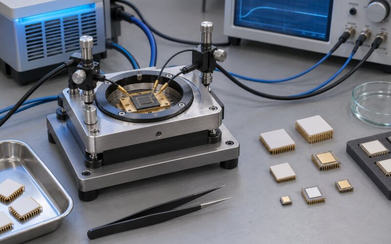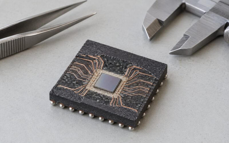
HAST and thermal cycling are accelerated reliability tests that put an assembled IC package under stress for hundreds or thousands of hours’ worth of field damage compressed into days. They are not interchangeable: HAST drives moisture and corrosion into a non-hermetic package using heat, humidity and pressure, while thermal cycling drives mechanical fatigue into die attach, bond wires and solder using repeated temperature extremes. A part can pass one and fail badly in the other’s failure mode. That is the whole of HAST and thermal cycling tests explained in one line: moisture versus mechanical strain, two test families answering two different questions.
One clarification before anything else. Here HAST means Highly Accelerated Temperature and Humidity Stress Test, defined in JEDEC JESD22-A110. It has nothing to do with HALT or HASS, which are vibration and over-stress screening methods, and nothing to do with the clothing brand or the school that share the acronym. If you arrived searching “hast”, this is the semiconductor test.
Table of Contents
- What Are HAST and Thermal Cycling Tests?
- Why Are Both Tests Used in IC Packaging?
- How HAST and Thermal Cycling Tests Differ
- How Accelerated Humidity Stress Testing Works
- How Thermal Cycling Works
- Typical Test Conditions and Relevant Standards
- What Failure Mechanisms Do These Tests Reveal?
- How to Prepare Samples and Test Equipment
- How to Control Common Sources of Test Error
- How to Interpret HAST and Thermal Cycling Results
- When to Use HAST, Thermal Cycling, or Both
- Frequently Asked Questions
- Is HAST the same as a humidity soak test?
- How many thermal cycles are normally required for an IC package?
- Can HAST or thermal cycling be performed with the device powered?
- Which test is more likely to find solder-joint cracking?
- How many samples should be used for a qualification test?
- Does a failure during stress testing always indicate a manufacturing defect?
- Conclusion
What Are HAST and Thermal Cycling Tests?
HAST is a JEDEC reliability test defined in JESD22-A110 that subjects non-hermetic packaged devices to elevated temperature, high relative humidity and elevated chamber pressure, so moisture penetrates to the die surface in hours rather than months. The point is to surface moisture-driven damage early enough that a design or process fix is still affordable.
Temperature cycling, defined in JESD22-A104, repeatedly moves a device between a low and a high temperature extreme so the mechanical interfaces fatigue through differential thermal expansion. Typical conditions run from minus 55 C to plus 125 C for 1000 cycles. Nothing is humid, nothing is pressurised, and nothing needs to be powered.
Both are acceleration tests. That means you trade realism for time: you push the sample harder than the field will, on the assumption that the dominant wear mechanism does not change character inside the accelerated regime. When that assumption holds, 96 hours in a HAST chamber represents a meaningful slice of product life.
Why Are Both Tests Used in IC Packaging?
Mould compound is not a hermetic seal. It is a polymer filled with filler, and water diffuses through it along a predictable path: from the compound surface, through the compound itself, along the interface to the die attach film, and finally to the bond pads and metallisation. HAST attacks that path directly.
Thermal cycling attacks a different path. A QFN contains silicon, copper lead frame, mould compound, die attach epoxy and solder, and those five materials expand by different amounts when heated. Heat them, cool them, and the strain concentrates at the interfaces. Repeat a thousand times and you get wire bond fatigue, attach cracks and delamination that would take years outdoors.
Neither test finds everything. A device with a perfect mould compound seal but a weak die attach will sail through HAST and crack under cycling. A device with an excellent attach but a permeable compound will pass cycling and corrode under HAST. Qualification plans run both precisely because the blind spots are complementary.
How HAST and Thermal Cycling Tests Differ
Here is the comparison that most supplier lab pages never put in one place.
| Attribute | HAST | Temperature cycling |
|---|---|---|
| Principal stressor | Moisture plus heat, accelerated by pressure | Repeated thermal expansion and contraction |
| Humidity | Controlled, typically 85 percent RH | Dry or ambient; not controlled |
| Pressure | Elevated above ambient, often 2 to 4 bar | Ambient |
| Driving mechanism | Water vapour pressure and diffusion kinetics | Coefficient of thermal expansion mismatch |
| Typical duration | 96 to 264 hours | 1000 cycles |
| Measurement approach | Hold time, not cycles | Cycle count, not hold time |
| Equipment | Pressure-controlled humidity chamber | Two-zone or single-zone climatic chamber with transfer |
| Main failure modes | Corrosion of metallisation, leakage current rise, delamination, popcorning | Bond wire fatigue, die attach cracking, solder fatigue, package delamination |
| JEDEC method | JESD22-A110 (biased or unbiased) | JESD22-A104 |
| Typical package focus | Moulded, non-hermetic plastic packages | Any package with dissimilar materials, plus board-level assemblies |
One more practical difference: a HAST chamber needs pressure plumbing, a humidity capable of 85 percent RH at 130 C, and usually a purge or dry-air step to protect the chamber when pressure is released. A temperature cycling chamber is mechanically simpler but needs good transfer control, because an uncontrolled transfer shock is really an accidental thermal shock test.
How Accelerated Humidity Stress Testing Works
The physics is diffusion. Moisture moves through mould compound at a rate that rises sharply with temperature, following roughly an Arrhenius relationship with an activation energy on the order of 0.4 to 0.8 eV depending on the compound. Raise the temperature from 85 C to 130 C and you get a large multiplier on the diffusion rate.
Pressure does the rest. Inside a sealed chamber, water vapour pressure at 130 C and 85 percent RH is far above the partial pressure in ordinary air at room temperature. That vapour pressure difference is what pushes water deeper into the compound and along interfaces in a few hours rather than a year of ambient exposure.
There is no single universal HAST recipe. The profile is application specific, and the test comes in two forms. Biased HAST holds the device under a steady electrical bias or dynamic load so that moisture-induced damage can show up as leakage current drift. Unbiased HAST, written up as UHAST in JESD22-A118, leaves the device unpowered and then measures it afterwards, which isolates materials damage from electrical over-stress.
One commonly cited condition is 130 C at 85 percent RH for 96 to 264 hours. Treat that as an example, not a requirement: the correct exposure comes from the qualification plan and the use environment your product actually ships into.
How Thermal Cycling Works
A thermal cycling profile is defined by four numbers: the low temperature, the high temperature, the dwell time at each, and the transfer time between them. For a commercial part the classic profile is minus 55 C to plus 125 C with a dwell of around ten minutes at each extreme and a transfer time of no more than a minute, repeated for 1000 cycles.
Dwell matters more than most people expect. Material needs time to equalise, and interfaces need time to redistribute stress. Cut dwell to a few minutes and the package spends the test in a temperature gradient rather than at temperature, which changes what you are measuring.
Transfer time is the part people get wrong. A slow, controlled transfer gives the chamber control of the sample’s temperature history. A fast transfer, or a chamber with a slow door, creates condensation on cold parts and thermal shock on the way out of the cold soak. Both corrupt the result.
Board-level assemblies use the same chamber logic with the added complication of solder joints, so the JESD22-B series and standards such as IPC-9701 cover that ground. On a bare packaged device, the strain concentrates at the die attach and the bond wires instead.
Typical Test Conditions and Relevant Standards
Read the numbers below as typical practice drawn from qualification reports, not as normative requirements. The JEDEC documents define the method, the severity levels and the reporting; the specific conditions come from the qualification plan.
| Test | Typical conditions | Duration or cycles | Method |
|---|---|---|---|
| HAST, biased | 130 C, 85 percent RH, 2 to 4 bar | 96 to 264 h | JESD22-A110 |
| HAST, unbiased (UHAST) | 130 C, 85 percent RH | 500 to 1000 h | JESD22-A118 |
| Temperature cycling | Minus 55 C to plus 125 C, 10 min dwell | 1000 cycles | JESD22-A104 |
| Power temperature cycling | Minus 40 C to plus 125 C with power cycling | 1000 cycles | JESD22-A105 |
| Temperature humidity bias (THB, 85/85) | 85 C, 85 percent RH | 1000 h | JESD22-A101 |
| Moisture preconditioning | Reflow or soak per MSL rating | One or more cycles | JESD22-A113 |
Two related methods sit next to these on most lab service pages and get confused with them constantly. Thermal shock is a different test: the sample is transferred between two extreme-temperature baths so fast that the core never reaches equilibrium. It is harsher per transition but far shorter in total, and it is not a substitute for cycling. And 85/85, or THB under JESD22-A101, is the slow reference that HAST is measured against: same humidity idea, no pressure, roughly ten times the hours.
| Standard | What it covers in plain English |
|---|---|
| JESD22-A101 | Temperature humidity bias, the classic 85 C and 85 percent RH steady-state test |
| JESD22-A104 | Temperature cycling, the method behind the minus 55 C to plus 125 C profile |
| JESD22-A105 | Power and temperature cycling, adding electrical load during transitions |
| JESD22-A110 | HAST itself, the biased accelerated humidity stress test |
| JESD22-A113 | Preconditioning of non-hermetic surface mount devices before stress |
| JESD22-A118 | Unbiased HAST, humidity stress without power applied |
| JESD47 | The stress-test-driven qualification flow that decides which tests a product needs |
| AEC-Q100 | The automotive qualification matrix that references the same JEDEC methods with grade-specific severity |
IEC 60068-2-14 is the equivalent temperature cycling method used outside the semiconductor world, so a lab servicing both electronics and industrial hardware will quote either one.
What Failure Mechanisms Do These Tests Reveal?
Matching a condition to a mechanism is how you decide what to go look at after a failure.
| Test and condition | Likely defect | How it is confirmed |
|---|---|---|
| HAST with bias | Corrosion of bond pad metallisation | Leakage current rise, cross-section of the pad |
| HAST after preconditioning | Delamination or voiding at the compound and die attach interface | Scanning acoustic microscopy, cross-section |
| HAST after reflow preconditioning | Popcorning in the mould compound | Visual and X-ray inspection |
| HAST, long duration | Leakage path along the die surface or under the attach | Parametric shift, surface analysis |
| Thermal cycling, cold to hot | Bond wire fatigue or bond lift | Cross-section or dye and pry |
| Thermal cycling, long soak | Die attach cracking | Cross-section, SAM |
| Thermal cycling, board level | Solder joint fatigue cracking | Dye and pry, X-ray of the joint |
| Thermal cycling, extreme CTE mismatch | Package delamination at the lead frame | SAM, cross-section |
The practical split is this: anything that gets worse with moisture gets worse with time, so HAST compresses that time. Anything that gets worse with repeated mechanical strain gets worse with cycle count, so thermal cycling compresses that instead.
How to Prepare Samples and Test Equipment
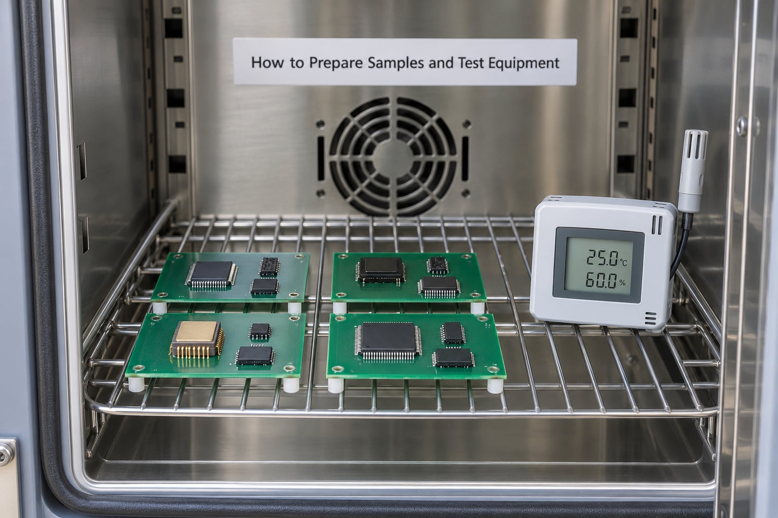
Sample preparation decides whether the run is worth anything. Start with specimen identification: every part gets a unique ID that follows it through preconditioning, stress, electrical test and failure analysis. On a mixed lot, mislabelled samples are the most common cause of a false failure call.
Preconditioning comes next. Non-hermetic surface mount devices are soaked and reflowed to their moisture sensitivity level before stress, so that the test starts from a realistic as-soldered moisture state rather than a dry one. Skip it and you have tested a condition that rarely exists in the field.
Then confirm the chamber. Check calibration status, verify the temperature and humidity uniformity across the working volume at the extremes you will use, and make sure the data logger records at a fine enough interval to catch a transient. For biased HAST, validate the power delivery: voltage at the load, current draw, and whether the bias pattern matches the application’s real duty cycle.
Loading matters more than most labs admit. Samples near the chamber wall or under the air plenum see different conditions than samples in the middle, so place them where the uniformity map says conditions hold. Leave spacing between parts so air can move. If a socket or fixture is used, verify it is rated for the full temperature range and does not itself introduce contact resistance that will be mistaken for part drift.
Finally, document the run before you start: chamber ID, calibration record, sample list with serials, fixture details, profile file version, and who approved it. Chain of custody that stops at the chamber door tells you nothing when a failure shows up three weeks later.
How to Control Common Sources of Test Error
Condensation on a cold sample turns a humidity test into an unintended water immersion test. Dew point alone produces big, occasional droplets rather than the uniform exposure you designed for. Control it by confirming that the chamber dew point stays below the sample temperature throughout the profile, and by handling the chamber so a part never meets humid air far below its dew point.
Fixture shadowing reduces airflow around a part and quietly changes its temperature. Standard spacing and a documented loading pattern fix most of it. Load nonuniformity between test slots is the same problem with a different symptom: one slot runs hotter than its neighbour. Measure across the fixture before you trust the data.
Unstable power is the quiet killer in biased testing. A bias supply that droops under a moisture-damaged part will produce a current spike that looks like catastrophic failure rather than progressive damage. Use a supply with current limiting, log the supply voltage alongside the part, and check the log when you review failures.
Unrecorded thermal transients mean your profile is not the profile you think. Chambers move between extremes quickly; if your logger interval is too coarse you will miss overshoot on ramp. Watch the recovery period too: parts pulled immediately from a hot soak are still hot, and measuring them too early produces parametric shifts that recover on their own.
How to Interpret HAST and Thermal Cycling Results
The first job is to decide whether a failure is real. Start by separating product failures from setup anomalies: a failure confined to one chamber position, one fixture slot or one power channel is a fixture problem until proven otherwise. Pull the neighbours from the same batch and see whether they behave the same way. If the whole slot failed and nothing else did, the slot is your suspect, not the design.
Then characterise the electrical signature. A slow leakage current rise that tracks exposure hours is the classic moisture signature, especially if it improves after a bake. A parametric shift in threshold voltage that appears immediately after the cold soak points to a mechanical strain or a bad attach instead. A resistance that jumps at one cycle and then stays flat suggests a cracked or contaminated contact rather than gradual fatigue.
Do not over-generalise from a small sample. Three parts out of three is a signal to investigate, not a failure rate. Cross-section or scan the failures before you write a root cause, because “delamination” and “delamination plus corrosion of the pad underneath” lead to very different corrective actions. And compare across lots and designs where you can, because a single-lot result says more about the process window than about the architecture.
Set acceptance criteria before the run, not after. Leakage current limits, allowed parametric shift, and the required sample size all belong in the qualification plan. Deciding what counts as a failure once you already have the data is how qualification programs lose credibility.
When to Use HAST, Thermal Cycling, or Both
The choice follows from the package architecture and the failure mechanism you are worried about. A moulded, non-hermetic plastic package with exposed bond pads and no lid is a moisture suspect first: HAST leads. A package with large CTE spread across mould compound, lead frame, attach and a thick die, or a board assembly with fine-pitch solder, is a mechanical suspect first: thermal cycling leads. And for anything shipping into an environment with both temperature swings and humidity exposure, running both is the only defensible choice, because the combination sometimes produces damage neither test shows alone.
That interaction is the argument for sequencing the tests. A HAST run followed by a temperature cycling run is common in mature automotive programmes, and the sequence can surface damage from moisture weakening a bond or an interface that separate runs never expose, simply because each test leaves the package a little worse and the next one applies load to a changed structure.
Budget and schedule push the same logic. A full HAST run on several lots takes a chamber for days; a 1000-cycle temperature cycling run takes a chamber for weeks, since the cycle time is dominated by dwell and transfer. When time is short, run the test that matches the hypothesised mechanism rather than the cheapest one, and be explicit in the plan about what you have chosen not to test.
Frequently Asked Questions
Is HAST the same as a humidity soak test?
No. A humidity soak such as 85/85 runs at 85 C and 85 percent relative humidity without added pressure, and it typically needs about 1000 hours to accumulate meaningful moisture damage. HAST adds elevated chamber pressure and usually runs hotter, around 130 C and 85 percent RH, so it reaches a comparable damage state in 96 to 264 hours. Same underlying mechanism, different acceleration. Use the soak as the reference and HAST when you need the answer faster.
How many thermal cycles are normally required for an IC package?
For a commercial plastic package, the common JEDEC JESD22-A104 profile is 1000 cycles between minus 55 C and plus 125 C with a dwell of roughly ten minutes at each extreme and a transfer time of no more than a minute. Automotive and industrial programmes sometimes shorten the range or run more cycles depending on the use environment. The cycle count comes from the qualification plan and the field temperature profile, not from the standard alone.
Can HAST or thermal cycling be performed with the device powered?
It depends on which test and what you are trying to find. Biased HAST under JESD22-A110 holds the device under steady or dynamic electrical load, which is how leakage current drift becomes visible during exposure. Unbiased HAST (UHAST, JESD22-A118) leaves the device unpowered and measures it afterwards to isolate materials damage. Temperature cycling is normally unbiased, though JESD22-A105 adds power cycling to temperature cycling for parts where electrical heating matters.
Which test is more likely to find solder-joint cracking?
Thermal cycling, by a wide margin. Solder fatigue is driven by repeated differential expansion between the board laminate and the package, so every cycle adds a little damage and a 1000-cycle run is designed to accumulate it. HAST can expose moisture-driven weakness that later contributes to cracking, but it is not the test that finds the crack itself. On board-level assemblies, standards in the JESD22-B series are built specifically around this failure mode.
How many samples should be used for a qualification test?
Sample count comes from the qualification plan and the confidence you need, not from a single number. JESD47 structures the qualification flow so that each stress test uses a defined lot and sample allocation, and AEC-Q100 applies grade-specific expectations on top of that. Common practice is to spread samples across at least three lots for a production process, and to define accept and reject criteria before exposure begins so the result is statistically meaningful rather than anecdotal.
Does a failure during stress testing always indicate a manufacturing defect?
No, and assuming it does is expensive. Failures traceable to chamber position, fixture contact, power instability or handling damage are test setup problems, and they usually cluster in one slot, one board or one time window rather than appearing at random. Establishing that pattern is the first step of analysis, before any cross-section. A failure that spreads across lots and positions under a confirmed-valid profile is much stronger evidence of a design or process weakness.
Conclusion
Start with the package architecture and the failure mechanism you actually suspect. A non-hermetic moulded package with exposed metallisation points to HAST under JESD22-A110, biased if you want to watch leakage during exposure and unbiased if you want to isolate the materials. Large thermal expansion mismatch, fine-pitch solder or a heavy die points to temperature cycling under JESD22-A104, with dwell and transfer time set deliberately rather than left to the chamber. Then match the profile to the standard and to your product’s use environment, and write the accept and reject criteria before the first sample goes in.