Lead free solder in electronics is any fusible metal alloy used to join electronic components that contains no intentionally added lead. Almost all of it is tin, with small amounts of silver, copper, bismuth, nickel, zinc or antimony added to control melting behaviour and joint properties. The most common family is Sn-Ag-Cu, better known as SAC.
The practical difference between lead free solder and the traditional Sn63Pb37 alloy is temperature, wetting behaviour and joint ductility. Lead free melts roughly 20 to 45 C higher, flows less freely, and produces a harder, less forgiving joint. That difference is why a board that was trivial to solder with 63/37 suddenly becomes finicky after the alloy switch.
This guide covers what lead free solder in electronics actually does at the joint, which alloy families exist, what temperatures work, how to run a repeatable bench process, and how it compares to leaded solder. It is written for PCB designers, process and hardware engineers, rework technicians and serious hobbyists.
Table of Contents
- What Is Lead Free Solder in Electronics Explained?
- How Does Lead Free Solder Work?
- What Is Lead Free Solder Made Of?
- What Are the Main Benefits and Drawbacks?
- What lead free genuinely fixes
- What lead free genuinely costs you
- Two misconceptions worth dropping
- What Temperature Should You Use for Lead Free Solder?
- Where Is Lead Free Solder Used in Electronics?
- How Do You Solder Electronics with Lead Free Solder?
- Common defects and what causes them
- Lead Free Solder vs Leaded Solder: What Changes?
- How Can You Tell If a Solder Is Lead Free?
- What Reliability Problems Can Lead Free Solder Cause?
- How Do You Choose the Right Lead Free Solder?
- Frequently Asked Questions
- Is lead free solder as easy to use as leaded solder?
- Why does lead free solder require a higher temperature?
- Can lead free solder be used on existing leaded PCBs and components?
- How can I identify whether solder wire is lead free?
- What flux should I use with lead free solder?
- Can lead free solder be used for high-reliability electronics?
- Conclusion
What Is Lead Free Solder in Electronics Explained?
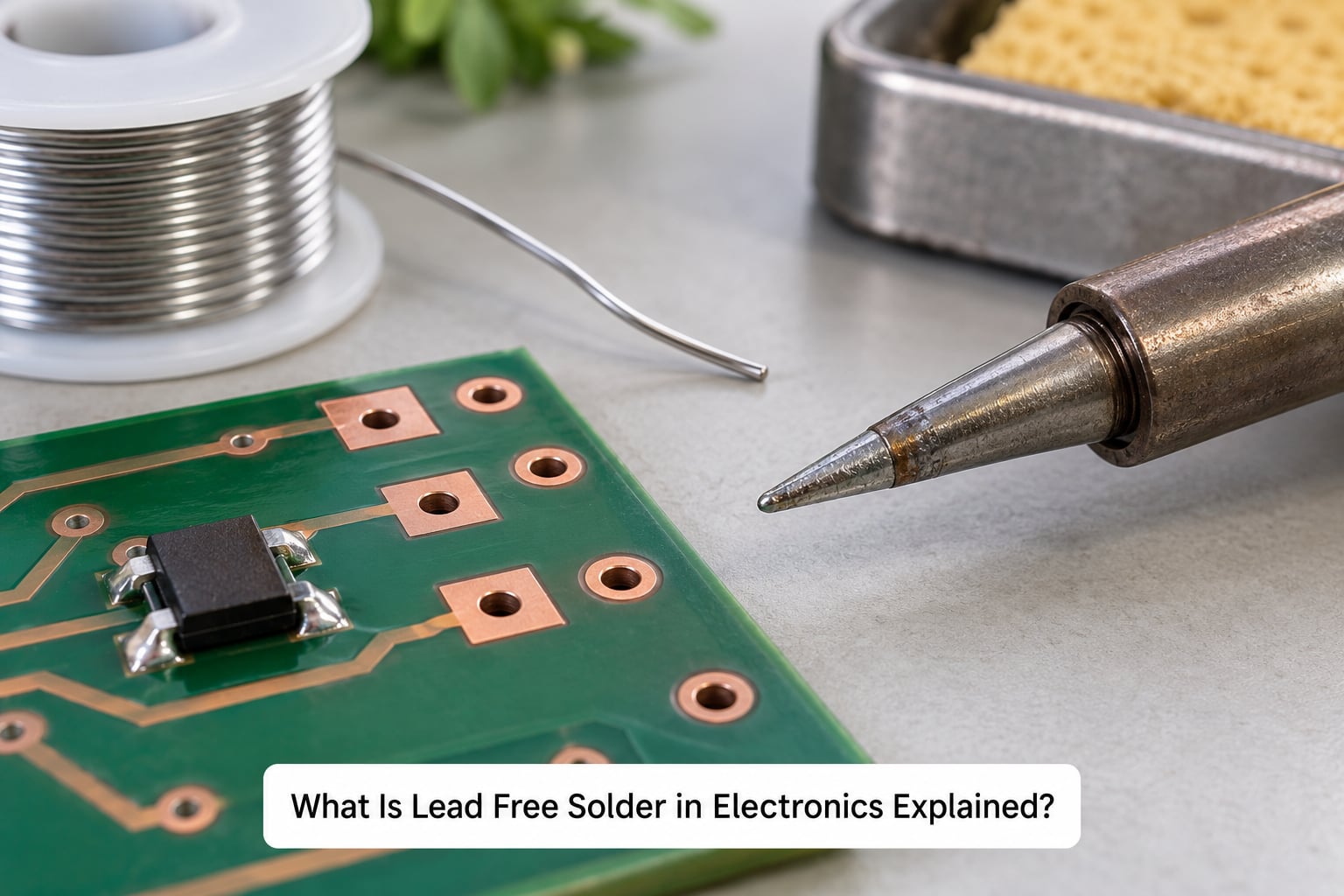
Lead free solder in electronics explained in one line: it is a solder alloy built around tin rather than lead, formulated so it melts at a workable temperature, wets copper and component leads, and forms a reliable metallurgical bond without adding lead to the supply chain.
By composition, commercial lead free solder is typically 95 percent or more tin. The remainder is added for specific reasons. Silver raises strength and helps thin joints hold together on fine-pitch packages. Copper, at well under one percent, forms the interfacial layer that bonds to the pad and reduces copper dissolution from the board. Bismuth or indium drop the melting range. Nickel, antimony, zinc and germanium appear in alloys aimed at specific strength or temperature targets.
RoHS is the reason this material exists in volume production today. The EU directive took effect on 1 July 2006 and restricted lead in electrical and electronic equipment, and it has remained in force, with amendments, in 2026. The contamination that drove it was not a factory problem. Lead leaching out of landfilled end-of-life equipment had been detected in groundwater across Europe and North America through the 1980s and 1990s.
Key characteristics worth remembering:
- Melts about 20 to 45 C higher than Sn63Pb37, which melts at roughly 183 C
- Wets more slowly and resists spreading, so more dwell time and more active flux are needed
- Produces stronger but less ductile joints, with a thicker brittle intermetallic layer at copper interfaces
- Carries a material cost premium from silver content, largely offset by energy and tip costs elsewhere
- Is the default for consumer, computing, telecom and most automotive electronics under RoHS
How Does Lead Free Solder Work?
Solder works because it melts at a lower temperature than the metals it joins. When the alloy reaches its liquidus, the molten metal wets the component lead and the board pad, and an intermetallic compound forms at the interface. On cooling, that bond becomes a mechanical and electrical connection that does not need to be a continuous piece of metal.
The process sequence is the same for every solder alloy, and the steps matter more than people expect.
- Heat the joint to the liquidus. For SAC305 that means roughly 217 to 220 C. Below liquidus the alloy is a solid lump that simply sits there and beads up.
- Let flux do its work. Flux removes oxides from the lead and pad, and without it molten tin will not wet clean metal at all.
- Hold at temperature briefly. The joint needs a few seconds so the molten alloy can flow, wet and displace the flux. Lead free needs longer here than leaded, which is why patience beats brute heat.
- Feed solder to the joint, not the tip. Touching wire to the heated pad and lead lets the tip act as a heat source only. Feeding solder to a cold tip drops it as a blob that never wets properly.
- Withdraw the solder first, then the iron. Pulling the iron away while feed is still attached drags solder into a spike or an icicle.
- Cool without moving the part. A joint disturbed while solidifying is a cold joint, and it fails later under vibration or thermal cycling even when it passes a visual check.
This is soldering, not brazing and not welding. Brazing uses a filler metal that does not melt the base metal and typically works above 450 C. Welding melts the base metal itself, which would destroy a PCB and most components. Soldering sits in between: the filler melts, the base metal does not.
One more mechanical detail matters for lead free specifically. Molten SAC is more surface-tension driven and less able to creep along a surface than SnPb. That is why lead free joints look less shiny and spread less, and why it will sometimes roll into a ball if the pad is contaminated and you just keep heating it.
What Is Lead Free Solder Made Of?
Lead free solder is not one material. It is a family of tin-based alloys, and picking the wrong one is the most common reason a lead free process fails even when the temperature is right. Tin is the base in all of them; the alloying elements decide the melting range, the wetting behaviour, the cost and the reliability profile.
| Alloy family | Composition | Liquidus | Typical electronics use |
|---|---|---|---|
| SAC305 | Sn 96.5, Ag 3.0, Cu 0.5 | 217 to 220 C | General reflow and wave solder, consumer and computing hardware |
| SAC105 | Sn 98.5, Ag 1.0, Cu 0.5 | 217 to 220 C | Cost-reduced volume work where solderability is still acceptable |
| SAC305 plus bismuth | SAC305 with a small Bi addition | Below 217 C | Lower-temperature processing to protect heat-sensitive parts |
| SnCuNi | Sn 99.0 or so, Cu 0.7, Ni plus dopants | 217 to 220 C | Cost-driven reflow and selective soldering, no silver cost |
| Sn-Zn | Tin with roughly 9 percent zinc, small Bi | Around 200 C | Lower-temperature reflow, consumer appliances |
| Sn-Bi | Tin with bismuth, sometimes small Ag | 138 to 170 C | Very low temperature work, heat-sensitive assemblies and some step soldering |
For most people buying wire for bench work, SAC305 or a SAC305 variant is the right answer. It is what most board houses and contract manufacturers run, so a joint made with it behaves the way their process data assumes.
Silver is the reason the price is higher and also the reason joints survive. High-silver alloys produce strong, stiff joints but cost more and grow brittle intermetallics faster. Low-silver alloys like SAC105 trade some solderability and joint strength for cost, which is why they spread through high-volume consumer work. SnCuNi drops the silver entirely and works acceptably when the line is controlled, but it is unforgiving about oxidation and requires better flux and atmosphere control.
Sn-Bi sits at the other end of the scale. It melts far below SAC, which protects delicate parts, but bismuth alloys are brittle at room temperature and have poor thermal fatigue behaviour, so they are not a general replacement for SAC.
What Are the Main Benefits and Drawbacks?
The benefits are regulatory and environmental, and they are real. The drawbacks are process-related, and they are also real. Conflating the two is how lead free solder gets a bad reputation it partly does not deserve.
What lead free genuinely fixes
- Regulatory compliance. RoHS restricts lead in electrical and electronic equipment, and REACH treats lead as a substance of very high concern. Products shipped into those markets need lead free solder or a documented exemption.
- End-of-life leaching. Lead free removes the main source of lead leaching from dumped electronics. No lead in the alloy means no lead to leach, regardless of what happens to the board afterwards.
- Lower handling risk at recycling. Recycling streams see less lead-bearing material overall, which simplifies downstream handling.
What lead free genuinely costs you
- Higher melting point. 20 to 45 C above leaded, which means more heat into the joint and closer to component limits.
- Poorer wettability. Slower spread, higher contact angle, and a joint that beads rather than flowing. Almost every bench complaint about lead free comes back to this.
- Shorter tip life. Hakko’s process guidance puts the reduction at four to five times versus conventional eutectic, because the higher temperature and the more aggressive flux attack the tip coating faster.
- Narrower process window. More flux activity is needed at a higher temperature, which increases the risk of carbonised residue, spitting and resin joints.
- Less ductile joints. Lead free tolerates vibration and thermal cycling worse than SnPb, and this is the one drawback that is metallurgical rather than fixable with technique.
Two misconceptions worth dropping
First, lead free is not automatically safer at the bench. Flux fumes are aggressive at both alloy families, and hot rosin fumes irritate regardless of whether lead is present. Practitioners on r/microcontrollers report that lead free flux fumes feel worse than leaded ones, and while that is largely about activity level and residue rather than lead, the perception is not imagined. Ventilation matters either way.
Second, lead free joints are not weak joints. They are harder and stronger in shear than SnPb. What they lack is ductility, which is a different property and one that matters when a board flexes.
What Temperature Should You Use for Lead Free Solder?
Keep two numbers apart in your head: the alloy melting range, which is a material property, and the iron tip temperature, which is a process setting. Conflating them is the single biggest cause of burned boards.
| Process | Leaded setting | Lead free setting |
|---|---|---|
| Bench iron, through-hole and rework | 340 to 350 C | 370 to 380 C |
| Reflow peak (component surface) | 235 to 245 C | 245 to 260 C |
| Time above liquidus | about 60 s | 60 to 90 s |
| Wave solder contact time | about 3 s | 4 to 5 s |
Set your iron a little above the liquidus so there is margin for heat loss into the pad and the lead. For SAC305 that lands at 370 to 380 C at the tip. Manufacturer and process specifications always take priority over any number in an article, including this one, because component packages, board laminates and tip designs vary.
Tip size changes the calculation more than people expect. A large chisel tip on a small through-hole joint dumps heat into the board and lifts the pad before it heats the lead. A fine point on a heavy chassis joint never gets hot enough and just oxidises. Match the tip to the thermal mass of the joint, not the other way round.
Pad finish matters too. ENIG gives a flat, uniform surface that wets predictably and resists bridging. OSP is inexpensive and wets well when clean but leaves an organic film that must be fully broken. HASL is uneven and tends to improve wetting while adding its own bridging risk at fine pitch. The rougher the finish, the more the molten alloy has to travel, and lead free needs that travel.
Watch the component limit before you raise the dial. Many packages are rated to 260 C peak for reflow, and some large BGA and leaded parts are not. When heat sensitivity and melting point conflict, the answer is a lower-temperature alloy family such as Sn-Bi or a SAC plus bismuth variant, not a cooler iron.
Where Is Lead Free Solder Used in Electronics?
Lead free solder is the default for anything sold into RoHS markets, which now covers most consumer and industrial electronics made anywhere in the world.
- Consumer electronics. Phones, laptops, televisions, audio gear and smart home devices all run SAC305 or SnCuNi in volume reflow.
- Computers and networking. Servers, switches and storage use lead free with controlled atmospheres, because voiding inside large BGA packages matters.
- Telecommunications. High-volume, thermally cycled infrastructure, typically SAC305 with strengthened paste and deliberate dwell times.
- Automotive electronics. ECUs and body modules use lead free, and OEMs add their own vibration and temperature-cycle qualification on top.
- Medical devices. Lead free is standard, subject to documented process control and often to specific customer process qualification.
- High-reliability and defence work. This is where the picture is mixed. RoHS exemptions exist for aerospace, military and medical applications, and many of these programmes still specify leaded high-temperature alloys because of their ductility and known fatigue behaviour. IPC J-STD-609 covers lead-free rework requirements where lead free is used in exempt sectors.
One-line disambiguation, because it comes up constantly in searches: this article covers electronics solder on PCBs and components. Lead free solder for plumbing and potable water is a different product with different rules and is out of scope here.
How Do You Solder Electronics with Lead Free Solder?
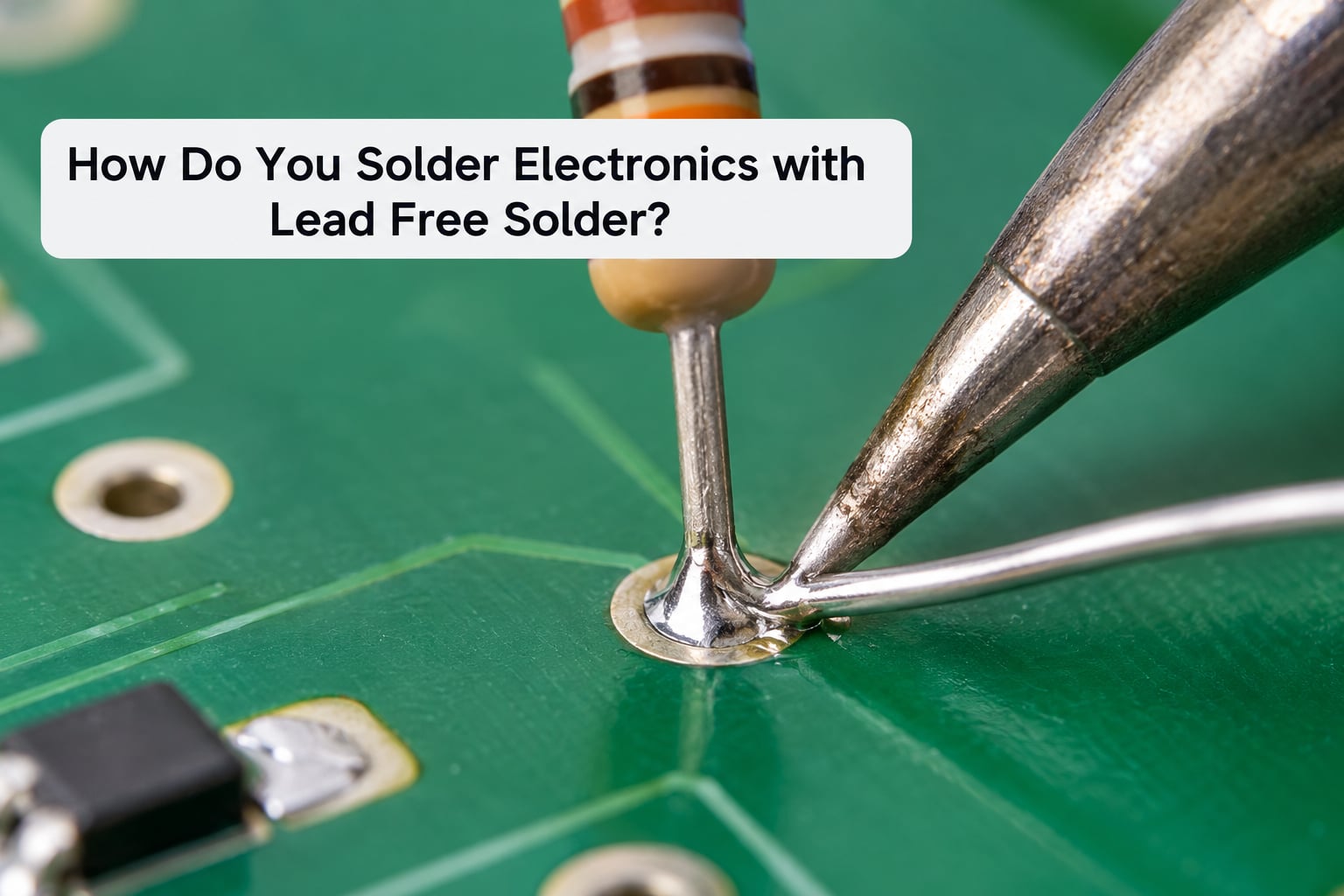
A workable lead free process comes down to preparation, heat, dwell and not moving the part. The sequence below works for through-hole joints, surface-mount rework and connectors alike.
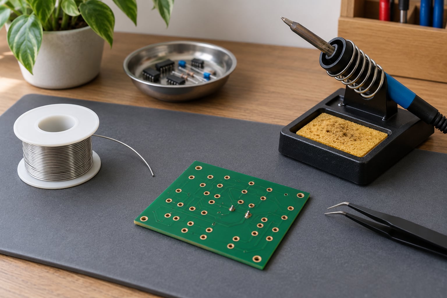
- Heat the iron to 370 to 380 C with a medium chisel or hoof tip for most through-hole work.
- Clean and prepare. Fresh pads, fresh leads, isopropyl alcohol on a lint-free wipe. Old flux residue is the leading cause of a joint that will not wet no matter how long you heat it.
- Use more active flux than you are used to. Standard rosin-core wire is often underpowered at lead free temperatures. A higher-activity no-clean flux or a liquid flux pen makes the difference between a joint that flows and one that beads. Apply it before heating, not after.
- Heat the pad and the lead together for two to three seconds before feeding any wire. Watching the solder melt and pull toward the joint tells you the temperature has reached the part.
- Feed the wire into the molten pool at the pad, not onto the tip, and keep the iron still.
- Remove the wire, then the iron, and leave the component alone until the joint has cooled to touch.
- Inspect and clean. A good lead free fillet is concave and dull, not a bright dome. Clean the residue with isopropyl alcohol and a brush before power-on.
For surface-mount rework on a populated board, add two rules. Lift the component with a low enough airflow that neighbouring parts stay put, and reflow the replacement pad rather than heating the whole joint area at once, because SAC bridges readily between adjacent pads on fine-pitch footprints.
If you are new to this, the advice on Electronics Stack Exchange is worth reading: a long-time hobbyist who always used leaded solder found lead free frustrating, and the honest conclusion is that most of that frustration was technique rather than material. The single biggest fix is more flux and more dwell, not more heat.
Common defects and what causes them
| Defect | Likely cause | Fix |
|---|---|---|
| Joint beads up and will not spread | Oxide or old flux residue on pad, or too little dwell | Clean the pad, add flux, hold heat three to five seconds longer |
| Bridging between adjacent pads | Excess solder, fine pitch, no-clean flux residue | Use a smaller tip, solder one pad at a time, wick the bridge, clean thoroughly |
| Icicle or spike on the joint | Iron withdrawn while feed wire was still attached | Remove wire first, then iron; reheat and reflow the spike flat |
| Cold joint, dull and cracked look | Joint disturbed while solidifying, or solder never fully melted | Reflow with fresh flux and leave it still until cool |
| Solder balls and solder spatter | Preheat too slow in reflow, or flux spitting at high temperature | Shorten preheat dwell, check reflow ramp, verify flux activation temperature |
| Tip blackens or burns out fast | Tip too cold for the alloy, or no re-tinning between jobs | Raise the temperature, re-tin the tip often, clean with a damp sponge while hot |
Lead Free Solder vs Leaded Solder: What Changes?
Lead free is harder, hotter and less forgiving than leaded solder, and it is now the compliance default. Everything a process engineer does changes as a result of that second point.
| Property | Leaded Sn63Pb37 | Lead free SAC305 |
|---|---|---|
| Composition | 63 percent tin, 37 percent lead | 96.5 percent tin, 3 percent silver, 0.5 percent copper |
| Melting point | 183 C eutectic | 217 to 220 C |
| Wetting and flow | Fast, spreads readily | Slower, resists spreading |
| Joint appearance | Bright, shiny fillet | Duller, more matte fillet |
| Ductility | Soft and forgiving under flex | Hard and brittle, less tolerant of stress |
| Thermal cycling and drop | Better fatigue life | Poorer unless the process is controlled |
| Iron temperature | 340 to 350 C | 370 to 380 C |
| Flux demand | Standard rosin is usually adequate | Higher activity no-clean flux typically needed |
| Compliance | Restricted in RoHS scope since 2006 | The standard choice for compliant product |
| Where each is still chosen | Exempt sectors, prototypes, rework on leaded boards | New production builds and compliant repair work |
One clarification: lead free does not mean lead is chemically absent from every product on your bench. It means the specified alloy contains no intentionally added elemental lead. Traces can still show up in analysis, and finished products carry other components, coatings and packaging that may contain lead within their own exemptions.
On the question of mixing alloys, give it a definite answer. Do not mix leaded and lead free on the same joint or the same board. The two alloys do not blend cleanly, the lead free portion will not wet the leaded residue, and the resulting mixed joint has unpredictable mechanical behaviour. Use the alloy the board was built with, or desolder and clean before reworking.
How Can You Tell If a Solder Is Lead Free?
Appearance will not tell you. A lead free joint and a leaded joint can look identical, and there is no bench test that reliably distinguishes them without lab equipment.
- Read the spool label. Alloy designations are printed on the label or the reel: SAC305, SAC105, Sn99Cu1, Sn100C. Anything without a Pb designation is lead free.
- Check the safety data sheet. The SDS lists the composition in section 3. Look for tin first, then silver, copper, bismuth, nickel or zinc. If lead appears above trace level, it is a leaded alloy.
- Ask the supplier for a declaration of compliance. For anything purchased for production work, request the RoHS declaration and the alloy certificate of analysis.
- Use X-ray fluorescence if you have access. Handheld XRF instruments can distinguish a high tin signal from a high lead signal on a solder sample, which is why they are common in incoming inspection.
- Send a sample for laboratory analysis. For contractual disputes or unknown legacy material, an accredited laboratory using ICP or similar methods gives a definitive answer.
Avoid destructive or unsafe home testing. Cutting into an assembled board, melting a sample to inspect colour, or heating wire over a flame tells you nothing reliable and puts fumes into your workspace. Flux fumes are the real inhalation hazard in soldering, not the metal.
What Reliability Problems Can Lead Free Solder Cause?
Most lead free reliability failures come from process control, not from the alloy label. That said, there is a genuine metallurgical mechanism that makes lead free joints behave differently over time, and it is worth understanding.
When molten tin contacts copper, it reacts to form intermetallic compounds, Cu6Sn5 first and Cu3Sn6 underneath. In leaded solder, lead sits at the interface and slows this reaction. Without lead, tin and copper react more freely, producing a thicker brittle layer at the joint. Every thermal cycle grows that layer further, and because it is brittle, it concentrates stress at its own boundary. A joint that is strong in new condition can crack at the interface after hundreds of temperature swings. This is why SAC alloy choice, dwell time and thermal design all matter for long-life products.
Other realistic failure modes:
- Insufficient wetting from contamination or too little flux, producing a joint with no metallurgical bond across part of the pad.
- Bridging and icicles from over-soldering on fine-pitch packages, which then short or fail under vibration.
- Voids in large thermal pads where outgassing and shrinking solder pull away from the centre of the joint.
- Tin whiskers in high-stress tin-rich and some zinc-bearing alloys, which are a real concern in long-life stored hardware.
- Residue-induced corrosion when aggressive no-clean flux is not cleaned after rework.
The honest summary: SAC performs well in normal consumer conditions with a controlled process, and it underperforms SnPb in high-vibration and severe thermal cycling applications. That is precisely why exempt sectors exist.
How Do You Choose the Right Lead Free Solder?
Choose the alloy that matches the assembly, not the one with the nicest melting point. Work through these in order.
- Assembly method. Reflow and wave usually mean SAC305 or SnCuNi. Hand rework and repair work best with a wire you can feed precisely, which is typically SAC305 with a no-clean core.
- Component and board finish. Fine pitch and ENIG or OSP surfaces favour higher silver content for wetting. Cost-driven consumer work often runs SAC105 or SnCuNi.
- Operating temperature and thermal cycling. Severe cycling pushes toward alloys with controlled intermetallic growth, and toward exemption strategies where they are available.
- Mechanical stress. Vibration-prone or flexing assemblies deserve particular scepticism about lead free, and a documented exemption where the programme allows it.
- Required reliability level. Define the qualification level first. IPC J-STD-001 defines acceptable soldering process classes, and IPC-A-610 defines what acceptable and defective look like. Test to a class rather than to a preference.
- Equipment compatibility. A common and expensive mistake is buying wire before checking that your iron, tips and heater can reach and hold the required temperature.
For a hobbyist at the bench, the practical list is short: SAC305 wire, 0.6 to 0.8 mm gauge for general work, a good no-clean or high-activity flux, a temperature-controlled iron, and medium chisel and hoof tips. That covers most repair work you will ever meet.
Frequently Asked Questions
Is lead free solder as easy to use as leaded solder?
No. Lead free solder runs hotter, flows more slowly and wets less readily, so it needs more active flux, longer dwell on the joint and a slightly higher iron temperature than Sn63Pb37. Experienced users on r/soldering and Electronics Stack Exchange generally describe leaded solder as easier at the bench, while also conceding that lead free produces harder joints. With correct flux and technique the difference is manageable, but it is real.
Why does lead free solder require a higher temperature?
Because the alloy itself melts higher. Sn63Pb37 is a true eutectic that melts at about 183 C, while SAC305 becomes fully liquid around 217 to 220 C. That 35 C gap is the entire reason for the higher iron setting. The trade-off is that the joint, the pad and the component all absorb more heat, which is why process specifications and component temperature ratings matter more with lead free than they ever did with leaded.
Can lead free solder be used on existing leaded PCBs and components?
You can physically solder lead free onto a leaded board, and on a non-critical repair it will usually hold. But for anything you care about, match the alloy the board was built with. Mixing alloys on one joint gives unpredictable bonding, and reworking a leaded joint with lead free without cleaning first is the most common cause of joints that will not wet. Do not mix leaded and lead free on the same board by choice.
How can I identify whether solder wire is lead free?
Check the label or reel for an alloy designation such as SAC305, SAC105 or Sn99Cu1. Then confirm against the safety data sheet composition section, where tin should appear first. Appearance tells you nothing, and there is no reliable non-destructive bench test. For production work, request a supplier declaration of compliance and certificate of analysis. Handheld X-ray fluorescence instruments can distinguish the alloys if you have access to one.
What flux should I use with lead free solder?
A higher-activity no-clean flux, either as a higher-activity core inside the wire or as a separate liquid flux pen. Standard rosin core is frequently underpowered at lead free temperatures, which is the usual reason a joint beads up instead of flowing. Apply flux before you heat, clean the residue with isopropyl alcohol afterwards, and keep ventilation good. Flux fumes irritate at both alloy families regardless of lead content.
Can lead free solder be used for high-reliability electronics?
Yes, and it is used in medical, automotive and telecom hardware every day, provided the process is qualified. The nuance is that SnPb joints are more ductile and generally survive severe thermal cycling and vibration better, so aerospace, military and some medical programmes rely on RoHS exemptions and still specify leaded high-temperature alloys. For long-life products, control intermetallic growth through reflow profile, alloy choice and thermal design rather than assuming the alloy alone carries the reliability.
Conclusion
Lead free solder is a controlled assembly material, not a drop-in swap. It joins metal at a higher temperature, wets more slowly, produces a harder and less ductile joint, and demands a more active flux and a tighter process than the leaded alloy it replaced. Put plainly, lead free solder in electronics is a tin-based alloy you work hotter, with more flux and more patience.
Start with SAC305 for the work in front of you, a temperature-controlled iron set around 370 to 380 C, a proper no-clean flux, and clean pads. Then match the alloy to the assembly method, the board finish and the thermal environment, and qualify to an IPC process class rather than to habit. That combination of alloy, flux, temperature, tip and process is what makes the difference between a joint that beads and a joint that holds for the life of the product.