Automated test equipment basics for beginners start with one idea: a machine applies known electrical signals to a part, measures what comes back, compares it to limits a person set beforehand, and records a pass or fail without anyone watching the readings. That whole cycle, repeated identically on every unit, is what turns a loose bag of components into a screened, shippable product.
One warning before we go further, because search results for this term are a mess. ATE here means physical hardware in a factory: a tester, a fixture, a probe card, real voltage and real current. It has nothing to do with the Selenium-and-Cypress world of software QA test automation. If you have been reading about scripting browser tests, you are in the wrong article. If you want to know what sits behind the pass/fail sticker on a chip, keep reading.
Table of Contents
- What Is Automated Test Equipment?
- Why Is Automated Test Equipment Used?
- How Does an ATE Test Work?
- Automated test equipment basics for beginners, step by step
- What Are the Main Parts of an ATE System?
- What Does ATE Measure?
- What Are the Common ATE Test Types?
- Wafer test (wafer sort)
- Probe test
- Final electrical test
- Burn-in
- System-level test
- Characterization and validation
- How Does a Test Program Work?
- What Are the Differences Between Digital and Analog Testing?
- How Do ATE Systems Affect Test Time and Cost?
- What Are Common Beginner Misconceptions About ATE?
- What Should a Beginner Learn Next?
- Frequently Asked Questions
- What are examples of automated test equipment?
- What does ATE stand for and what does it do?
- What is a device under test, or DUT?
- What is the difference between ICT and boundary scan?
- Is automated test equipment expensive?
- Can one ATE system test different types of chips?
- Where to Start With ATE
What Is Automated Test Equipment?
Automated test equipment, usually shortened to ATE, is computer-controlled machinery that electrically stimulates and measures a device under test, applies inputs, reads outputs, and compares those readings against pre-set limits to pass or fail the part. No operator judgement is involved in the measurement itself.
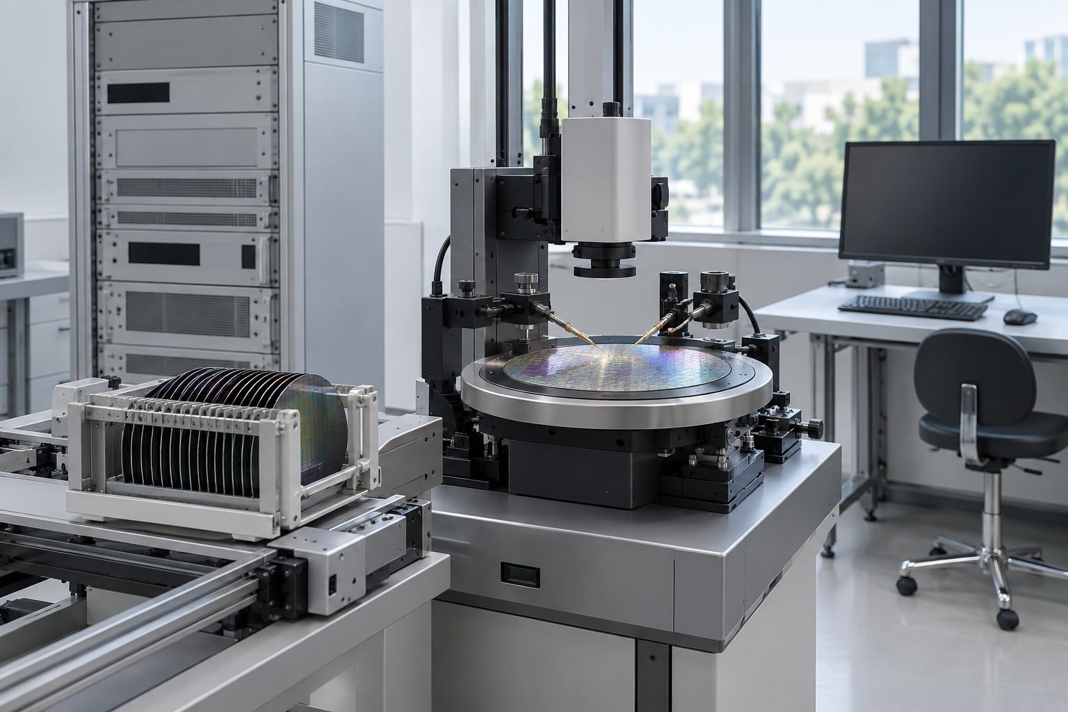
In practice, an ATE system is a rack of instruments, a way to touch the part electrically, and software that runs a sequence of measurements. The touching comes from a probe card on a wafer, a socket and load board for a packaged chip, or a bed-of-nails fixture for a populated circuit board.
The term gets used loosely in the electronics industry, so it helps to know the neighbouring categories. Inspection equipment like automatic optical inspection looks at a part to find visual defects. It does not measure electrical behaviour, so it cannot tell you a transistor is leaky. ATE measures; inspection watches. A burn-in chamber stresses parts at elevated temperature and voltage for hours. A functional tester exercises a board as if it were switched on in a real product. All of these are automated test equipment in the broad sense, but a test cell that measures DC parameters is a different machine from one that drives a display.
Why Is Automated Test Equipment Used?
Automated test equipment is used because hand testing does not scale and does not repeat. A technician probing boards all shift measures things slightly differently on Tuesday than on Friday, and a good unit can still slip through.
Five problems ATE solves come up repeatedly in manufacturing:
- Defect screening. Solder bridges, unpopulated parts, cracked packages, and dead inputs get caught before the part reaches a customer.
- Electrical performance measurement. Leakage current, resistance, timing, drive strength, and power draw get numbers attached instead of a pass stamp.
- Consistency. The same limits apply to unit one and unit one million.
- Yield data. Every measurement is logged, so process engineers can see which failures cluster and why.
- Throughput. One operator can run several test sites in parallel while the machine works.
That last point is usually the argument that wins the budget meeting. When a plant ships a few hundred boards a month, hand testing with a bench scope might genuinely be enough. At tens of thousands of units a month, an operator cannot keep up, and the escaped defects start costing more than the test cell did.
How Does an ATE Test Work?
A test cycle is a fixed sequence: load the part, connect it, run the measurements, compare against limits, log the data, decide pass or fail, and move on. The sequence repeats thousands of times with only the part changing.
Automated test equipment basics for beginners, step by step
- Load. A handler picks a part from a tube or tray, or a prober presents a die on the wafer, and positions it under the pins or probe card.
- Connect. Spring pins, a socket, or probe needles make electrical contact. Contact quality decides whether your measurements mean anything.
- Power up. Supplies bring the part to its operating voltage. Test engineers often measure current at startup, since a part drawing too much here is already suspect.
- Apply stimulus. Patterns, vectors, or analog signals go into the inputs. Digital testers drive a bit sequence; analog testers apply a voltage or current level.
- Measure. Instruments read outputs, voltages, currents, resistances, and timing. Each reading has a measurement name and a unit attached.
- Compare. A limit table holds a low and high bound for every measurement. Inside the bounds, the measurement passes.
- Log. The value, or a pass/fail flag, goes into a datalog record with the part serial number, the site number, and the timestamp.
- Decide and sort. The unit gets binned. Passing parts go to the good bin, failures go to a reject bin, and marginal parts may go to a separate bin for retest.
Step eight is the part beginners miss. A test program can fail a part for a reason that has nothing to do with the design, such as a marginal contact on a probe pin. Good test engineering separates “the part is bad” from “the test setup was not ready.”
What Are the Main Parts of an ATE System?
An ATE system has three big blocks: the tester that makes and measures signals, the interface that touches the part, and the software that decides what to do with the numbers.
| Component | What it does |
|---|---|
| Tester | The main instrument chassis. Holds pattern generators, digital channels, timing measurement units, and analog instruments. |
| Test head | The connection between tester and fixture, routing thousands of signal lines down to the part. |
| Load board | A small circuit board that adapts tester channels to the pins of one specific device family. Custom per product. |
| Probe card | Fine needles on a wafer prober that contact pads on bare die. |
| Fixture | A bed-of-nails plate for a populated circuit board. Custom mechanical and electrical design. |
| Prober | Moves the wafer and probe card together, stepping die to die. |
| Handler | Feeds packaged parts into the test socket and sorts them afterwards. |
| Power supplies | Provide operating voltage to the part under test. |
| Measurement instruments | Digital multimeters, oscilloscope channels, source measure units, spectrum or RF instruments. |
| Test executive | Software that runs the test programme, sequences steps, and manages results. |
| Datalog | Storage for every measurement, used later for yield analysis and failure trending. |
Vendor platforms like the Teradyne and Advantest tester families, the Cohu probers and handlers, and the National Instruments PXI and LabVIEW ecosystem all fill these slots in different ways. The names matter less to a beginner than understanding which box does which job on the test floor.
What Does ATE Measure?
ATE measures electrical quantities. If a value is not electrical, an instrument has to convert it into something a voltmeter or timer can read first.
| Measurement | Typical use |
|---|---|
| DC voltage | Supply rails, reference voltages, analog output levels |
| DC current | Active current, standby current, short detection |
| Resistance | Contact resistance, on-state resistance of a switch, fuse continuity |
| Leakage current | Input impedance checks, off-state isolation, screening for pinholes |
| Capacitance | Load capacitance on outputs, filter and pad checks |
| Timing | Propagation delay, setup and hold, access time, maximum frequency |
| Digital I/O | Walking a pattern into a port and checking what comes out, pin by pin |
| Mixed signal | Converter accuracy, distortion, noise, SNR |
| Memory operation | Programming a device and reading it back, including march algorithms |
| Power | Energy per operation, current versus time profiles |
| Functional result | Does the device do its job: boot a bootloader, decode video, lock a PLL |
Functional tests are the slowest and often the most valuable. A memory march test finds a stuck bit that a single read would miss, and a PLL lock test catches an analog problem no static voltage limit would reveal.
What Are the Common ATE Test Types?
The main ATE test types are wafer test, probe test, final electrical test, burn-in, system-level test, and characterization. Each answers a different question at a different point in the product’s life.
Wafer test (wafer sort)
Chips are tested while they are still on the wafer, before any packaging cost is added. Each die is probed, measured, and binned, so known good die can be shipped to assembly and bad die can be mapped out. This is where parametric test happens: DC and capacitance measurements on individual transistors and wells, which describe the process rather than the product function.
Probe test
Probe test is another name for the probing step itself, whether at wafer level or at package level with a contactor. The prober supplies the mechanical repeatability, stepping thousands of die without an operator touching anything.
Final electrical test
After packaging, the finished device goes back on a tester, often on a handler that loads parts automatically. The full test programme runs, the part gets a bin assignment, and a final test mark and shipping data are produced. This is the last electrical check before the part leaves the factory.
Burn-in
Parts run at elevated temperature and voltage for hours or days to force early failures to appear. A device that works at room temperature but fails hot shows up here rather than in a customer’s car.
System-level test
The board or module is powered up in its real configuration and exercised: firmware loads, interfaces connect, functions run. It catches assembly and integration problems that no single measurement would reveal.
Characterization and validation
Engineering runs a much longer sequence across voltage and temperature corners to describe how a design behaves. This is a development activity, not a production one, and it produces the data used to write production limits.
How Does a Test Program Work?
A test program is the set of instructions that tells the tester what to measure and what counts as a pass. People write it. The machine does not invent limits.
The building blocks are patterns, test cells, and limits:
- Pattern — the bit sequence or analog waveform applied to a set of pins.
- Test cell — one measurement step: a pattern in, a window, a compare, a pass or fail result.
- Timing and levels — edge positions and voltage thresholds referenced to a clock.
- Limits — the low and high bound, or the expected bit value, for each test cell.
- Bin and binning rules — where a failing part goes.
Typical test software stacks pair a programming environment with a test executive. LabVIEW with TestStand is the most familiar combination, and most PXI systems run on that pair, but other stacks exist and the underlying idea is the same: a test sequence on top, hardware control underneath, and a results database at the end.
Some limits come straight from the datasheet. Others are set statistically, using measured distributions from characterization runs, with guard bands that widen the window so marginal parts are not failed by normal spread. Getting those numbers wrong is the classic beginner mistake: too tight and good parts get rejected, too loose and defective parts ship.
What Are the Differences Between Digital and Analog Testing?
Digital testing drives known bit patterns in and expects known bit patterns out. Analog and parametric testing measures a continuous quantity against a numeric range. Mixed-signal testing does both, usually in sequence on the same part.
| Method | What it does | Strength |
|---|---|---|
| Digital pattern test | Applies vectors at set timing, compares captured output against expected | Fast, very high fault coverage on digital logic |
| Parametric test | Measures DC bias points, threshold voltages, leakage, capacitance | Describes process health and analog behaviour |
| Analog functional test | Applies a stimulus and measures a waveform or level | Checks real analog performance, not just a number |
| Mixed-signal test | Drives an analog input, checks the digital output, and the reverse | Covers converters and codecs end to end |
| Functional test | Runs a sequence of operations on a working part | Catches integration and firmware-level problems |
A beginner mistake here is treating analog and digital as competing methods. On a mixed-signal part they are complementary: the digital test proves the logic paths, the parametric test proves the bias points, and the functional test proves the two halves talk to each other.
How Do ATE Systems Affect Test Time and Cost?
Test time is the single biggest cost driver in a test cell, because it sets the size of the line and the number of machines you need. Adding a test does not just add its own seconds, it adds them for every unit you build.
Test time is reduced by running several sites in parallel. A cell with four sites tests four parts at once, so a two-second test becomes an effective half-second per part, as long as the parts are fed and sorted fast enough. Parallelism is limited by how fast the handler or prober can index, which is why motion is often the real bottleneck in a fast test.
Yield affects cost more than most people expect. Cost per good unit is total test cost divided by yield, so a process change that lifts yield from 90 to 95 percent can cut testing cost per shippable part more than negotiating a better instrument price.
These are the parts people forget when they budget a test cell:
- Fixture and load board development. Custom per product, and often the largest engineering item on the schedule.
- Test program development. Writing and debugging the programme, including correlation against a known good sample.
- Retest policy. Deciding what gets retested and how often, because retest can hide real failures if it is too generous.
- Calibration and maintenance. Instruments drift, and a cell that is out of calibration generates failures nobody can reproduce.
- Programming time. Loading device data into flash or fuses can take longer than the measurement itself.
- Operator and engineering time. Setup, board learning, and failure analysis all sit outside the cycle time.
Textbook primers on this topic warn against over-testing, and the warning holds. Every extra step raises cost per unit. Add a step only when it catches a failure mode the other steps miss.
What Are Common Beginner Misconceptions About ATE?
The biggest misconception is that automated test equipment repairs parts. It does not. ATE is a measuring instrument, and a failing part leaves the cell in the reject bin.
Six beliefs worth clearing up early:
- “ATE guarantees the design works.” It guarantees the design meets the limits you wrote. Weak limits mean weak screening.
- “ATE replaces inspection.” Optical and X-ray inspection find defects that no electrical measurement detects, such as a solder void under a BGA. Both stay in the flow.
- “One machine tests every product.” The tester may be reusable, but the load board, fixture, socket, and program are product-specific.
- “A pass means the part is perfect.” It means the part passed the tests that exist. Coverage you did not write is coverage you do not have.
- “Automated means hands-off.” Somebody owns the program, the limits, the calibration, and the failure analysis. The machine just does the typing.
- “A higher test percentage is always better.” Coverage has a cost, and beyond a point more steps find nothing new while slowing the line down.
That last one is worth saying twice to anyone new to yield work, because it is the first place where intuition misleads. A well-designed test plan looks more like a curated shortlist than a bigger pile.
What Should a Beginner Learn Next?
Learn electronics first, then test. A test engineer who cannot read a schematic will spend every debugging session guessing. Here is a sequence that works.
- Electronics fundamentals. Ohm’s law, voltage dividers, transistor behavior, op-amp basics, and what makes a signal a signal.
- Digital logic. Gates, flip-flops, clocks, setup and hold timing, and how a state machine becomes a pattern.
- Analog measurement. How a digital multimeter behaves, loading effects, why a 10x probe exists, and where noise comes from.
- Semiconductor vocabulary. Wafer, die, reticle, probe card, handler, package, burn-in, known good die.
- Datasheet reading. Take one simple part and pull every test condition out of it: voltages, currents, timing, and the limit tables.
- Hands-on with cheap gear. A development board, a multimeter, a USB oscilloscope, and a solderless breadboard will teach more than a textbook chapter. Boundary scan tools for JTAG parts run on a desktop and are a good second step.
- Learn one test software stack. Pick LabVIEW or an equivalent environment and build a simple measurement sequence, even if you never use it professionally.
- Read a real flow. Find a published test flow diagram and map each station to the ATE type that performs it.
- Learn basic statistics. Distributions, guard bands, Cpk, and why a limit set from one sample is a guess.
- Respect the safety rules. High-voltage and high-current test cells can be lethal. Never work inside one without training, and treat interlock bypass as a last resort under supervision, never a shortcut.
For the semiconductor side specifically, understanding parametric versus functional test and knowing what a probe station physically does will put you ahead of most people entering this field from software.
Frequently Asked Questions
What are examples of automated test equipment?
Common examples include wafer probers for testing bare die, handlers for packaged parts, bed-of-nails in-circuit testers, flying probe testers, boundary scan (JTAG) systems, functional test systems, and source measure unit based parametric testers. Inspection systems such as AOI and AXI sit alongside ATE in the same production flow but measure rather than inspect.
What does ATE stand for and what does it do?
ATE stands for automated test equipment. It is computer-controlled machinery that applies known electrical stimuli to a device under test, measures the response, and compares the reading against limits that an engineer defined. The result is a logged pass or fail with no operator judgement in the measurement.
What is a device under test, or DUT?
The device under test, abbreviated DUT, is the part being measured. It could be a bare die on a wafer, a packaged chip in a handler socket, or a populated circuit board in a fixture. The DUT board is a small adapter board that carries the DUT and routes tester channels to its pins.
What is the difference between ICT and boundary scan?
In-circuit test (ICT) uses a bed-of-nails fixture to touch component leads directly and measure individual parts, giving excellent coverage but needing a custom fixture per board. Boundary scan uses the JTAG pins a designer added for exactly this purpose, so no fixture is needed and it works on bare boards, at the cost of lower coverage.
Is automated test equipment expensive?
Cost varies by order of magnitude depending on what you are testing. Bench-level parametric and functional setups are modest. Volume production cells with handlers, multi-site capability, and custom load boards run into six figures, and the fixture and test program development often costs more than the hardware. Cost per good unit, not the machine price, is the number that matters.
Can one ATE system test different types of chips?
The tester itself is often reusable across many products, but the interface is not. Each device family needs its own load board, socket or probe card, fixture, and test program. Swapping products means changing all of those, which is why test cells are specified for a product family rather than a single part.
Where to Start With ATE
Start by reading one datasheet from end to end and pulling out every test condition and limit table inside it. That single exercise explains stimuli, timing, limits, and binning better than any definition, and it is the same work the first engineer on a new part does.
Then get your hands on something. A development board, a multimeter, and a USB oscilloscope will teach you measurement discipline, and a boundary scan tool will show you a real test sequence running against real silicon. Once you have watched a test program step through a part and produce a pass or a fail, the rest of the vocabulary stops feeling abstract.
Automated test equipment basics for beginners really come down to three habits: measure instead of assume, write the limits down before the production run, and treat every failure as information rather than as an obstacle to bin around.