Underfill in flip chip assembly is a bead of epoxy encapsulant dispensed along the edge of a bumped die and pulled by capillary action into the narrow gap between the die and its substrate, where it cures into a solid mechanical and thermal bond. It spreads coefficient-of-thermal-expansion strain away from the solder bumps, seals the interconnects from moisture, and is what turns a fragile solder array into a reliable package.
This guide is written for packaging, assembly and reliability engineers who specify, qualify or troubleshoot flip chip and chip scale packages on organic substrates. The process details reflect production practice reviewed for October 2026, with the published figures that still underpin most design rules.
Table of Contents
- What Is Underfill in Flip Chip Assembly?
- Why Flip Chip Assemblies Use Underfill
- How Underfill Works in a Flip Chip Package
- How underfill in flip chip assembly flows under the die
- Types of Underfill Materials
- Epoxy underfill
- No-flow underfill
- Silicone and acrylate materials
- How Underfill Is Applied
- What Controls Underfill Reliability?
- Common Underfill Defects and Failure Modes
- How to Choose the Right Underfill
- How do you calculate the volume of underfill needed?
- How Underfill Is Inspected and Tested
- Frequently Asked Questions
- What is underfill in welding?
- What causes voids in flip chip underfill?
- What is the difference between no-flow and capillary underfill?
- How do you calculate the volume of underfill needed?
- How long does underfill curing take?
- Can you rework an underfilled flip chip?
- Conclusion
What Is Underfill in Flip Chip Assembly?
Underfill is the material that fills the space between a flip chip die and the board or interposer it sits on, and it is placed there deliberately after the solder joints have been formed. Once cured, that filler-loaded resin becomes a load-bearing member of the package rather than a cosmetic cover.
It is worth separating underfill from the three things it is often confused with. Overmold or glob top is moulded or dispensed over the top and sides of an assembled component to protect it from impact and moisture, but it does not reach into the die-to-substrate gap, so it does nothing for CTE stress on the solder. Die attach adhesive is the separate adhesive used to bond a die to a package substrate, and it typically cures at a much lower temperature than a solder interconnect. Conformal coating is a thin board-level protective film brushed or sprayed over components, and it cannot survive the mechanical loads at the die edge.
The C4 bump is the other term that turns up constantly in this area. A C4 bump, also called a soldered-on micro-bumped bump, is a controlled-collapse interconnect formed by plating solder-capped copper pillars and spheres and then reflowing them so the solder collapses onto the die pads. Underfill is what comes next in the sequence.
Why Flip Chip Assemblies Use Underfill
The reason is a number mismatch. Silicon has a coefficient of thermal expansion near 2.4 ppm per degree Celsius, 95% alumina sits around 6.3 ppm, and typical FR-4 laminate runs at roughly 16 ppm. Every time an assembly goes through a temperature swing, the die wants to move about a seventh as much as the board does, and the entire difference has to be absorbed by the only flexible element in the joint, which is the solder bump.
That makes the bump the weakest point. Cutting a bump area in half roughly doubles the strain it carries, and a 300 micrometre CSP ball tolerates on the order of a quarter of the strain a 75 micrometre flip chip ball absorbs. Published design rules go further: doubling die area in one direction has been modelled at roughly a fourfold reliability penalty, while doubling substrate thickness recovers about a factor of two.
Underfill changes the load path. Because it bonds to the die backside, the solder joints and the substrate across the whole die area, it redistributes shear and peel strain from the individual bumps to the entire package footprint. In published temperature cycling data between minus 40 and 125 degrees Celsius, that redistribution typically multiplies cycle life by two to four, and some assemblies have survived past 2,000 cycles. It is a large enough gain that a device which would be specified with larger, more expensive bumps can often stay with its current interconnect.
The resin also does three quieter jobs. It seals the interconnects against moisture and ionic contamination, it keeps debris off the die backside, and it stiffens the joint against drop and vibration. The last part is the trade-off you inherit later, because an underfilled assembly is no longer reworkable with a hot plate.
How Underfill Works in a Flip Chip Package
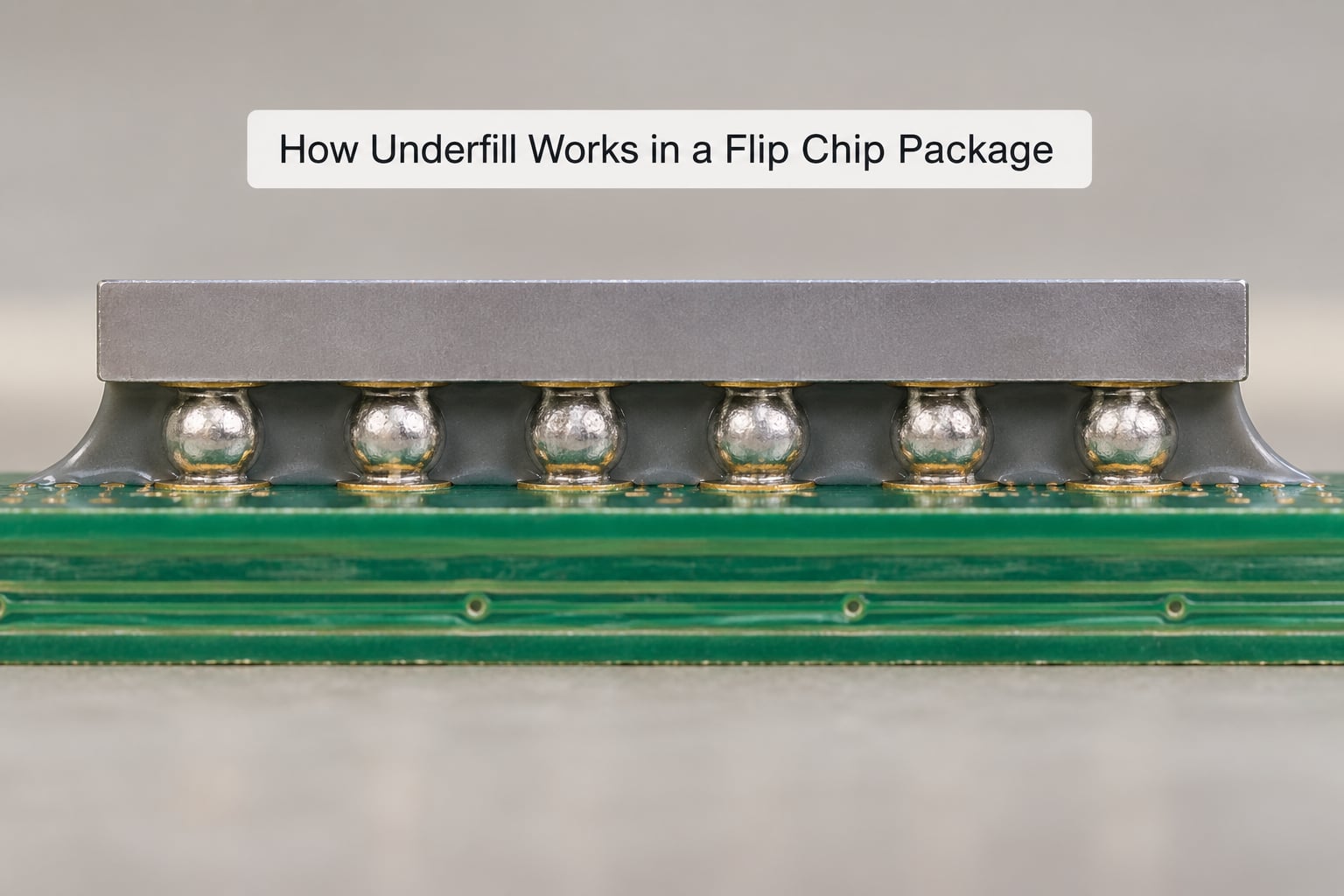
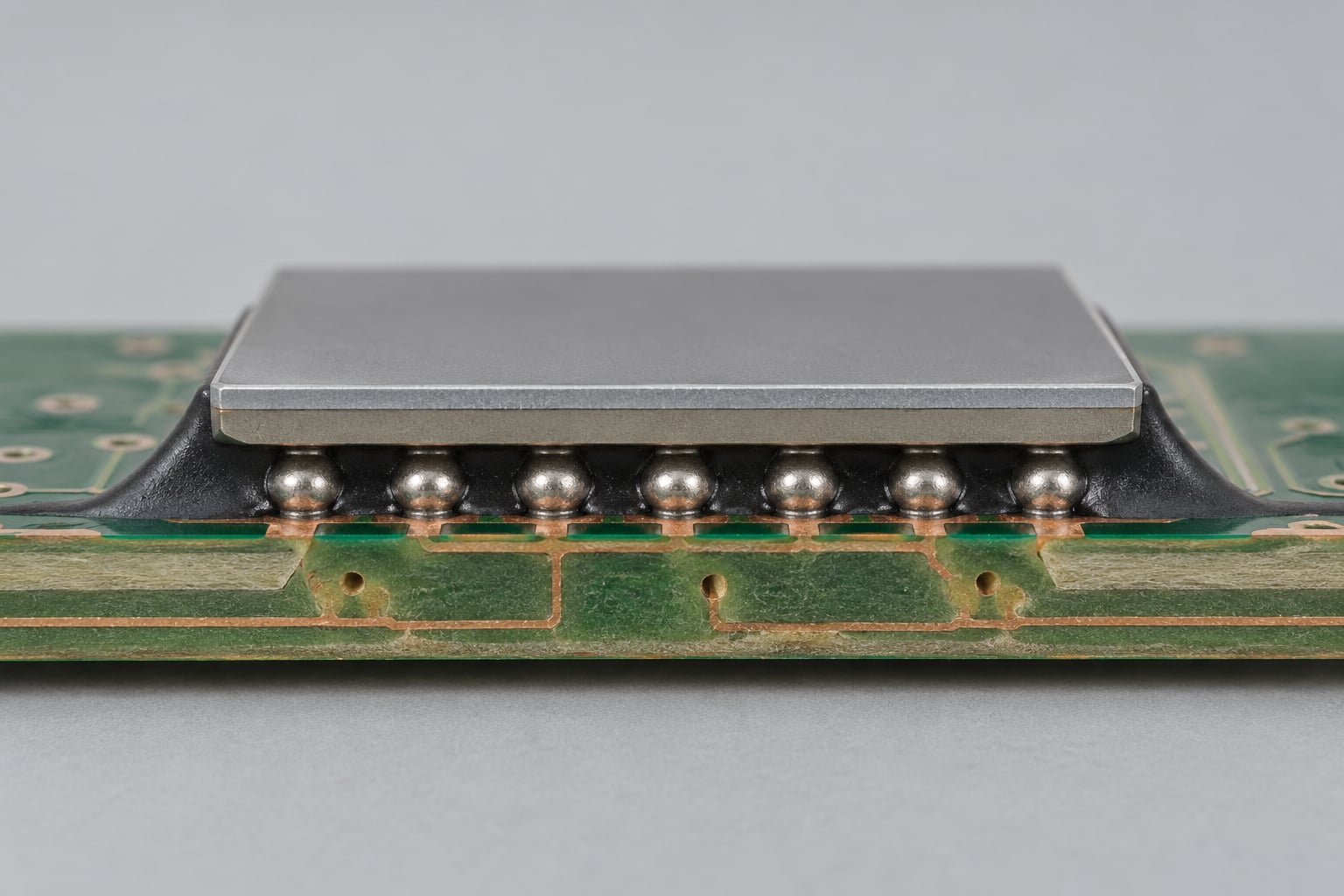
In cross-section the package is simple: die on top, bumps, a gap of tens to a few hundred micrometres, substrate below, resin occupying that gap plus a fillet up the die edge. The whole process is about filling that gap completely and curing it without trapping air.
Flip chip bonding itself works by creating a solder interconnect directly between the die pads and the board pads. The die is aligned to a substrate with flux, placed, and reflowed; each solder joint wets to both surfaces and forms its own intermetallic compound, which is what makes the mechanical and electrical connection. Underfill follows that reflow step rather than replacing it.
How underfill in flip chip assembly flows under the die
The flow is capillary, and the gap does the work. A narrow gap between two rough surfaces wets a low-viscosity resin far more readily than gravity or pressure would, and the flow front pulls material inward from the deposited bead until it meets the opposite edge and stops. Two details make the difference between a clean fill and a scrapped part: the epoxy must wet the surfaces it touches, and the path must be continuous.
After flow, a seal bead is often dispensed along the remaining die edge to trap the resin and build a fillet, then the assembly is cured. A thermal cure is most common, with cure schedules running from a few minutes at around 150 degrees Celsius to longer schedules at lower temperatures for materials chosen to survive a low-temperature reflow. The cure has to complete before the part moves, because an incompletely cured epoxy is soft, hygroscopic and vulnerable to moisture-driven delamination later.
Cleaning before dispense matters as much as the resin choice. Flux residue left on the substrate is a leading cause of voids and poor wetting. Some lines replace aggressive pre-cleaning with selective jet fluxing, which keeps throughput up while still controlling the residue under the die; published work found that under-die cleaning alone improved temperature cycling results by up to a factor of five.
Types of Underfill Materials
Most underfill in production is a filled epoxy, but four chemistry families cover almost all the commercial options, and the differences show up in the process rather than in a datasheet headline.
| Chemistry | Cure | CTE below Tg | Flexibility | Rework | Typical fit |
|---|---|---|---|---|---|
| Filled epoxy (standard capillary) | Thermal, minutes around 150 degrees Celsius | 25 to 45 ppm per degree Celsius | Low modulus, stiff joint | Not practical once cured | General purpose flip chip and CSP on organic substrate |
| No-flow epoxy | Thermal, reflow profile plus a cure window | 25 to 45 ppm per degree Celsius | Low modulus, stiff joint | Not practical once cured | Small die, lower I/O density, lines without a separate underfill step |
| Silicone | Thermal or moisture cure, wide window | Typically above 150 ppm per degree Celsius | High, stress-relieving | Possible on some assemblies | Severe thermal cycling where rework still matters |
| Acrylate | UV or thermal, seconds to a minute | Typically above 200 ppm per degree Celsius | Moderate | Possible with a thermal profile | Fast takt lines with good line-of-sight access to the gap |
Epoxy underfill
Standard two-part epoxies cure thermally, flow well at dispense temperature, and are loaded with 50 to 68 percent silica or alumina filler to bring the CTE down into the 25 to 45 ppm per degree Celsius range below the glass transition temperature. The filler is what makes the resin mechanically useful, and it is also why filler settling and viscosity drift on storage are real concerns. Above Tg the CTE rises sharply, which is why moisture-loaded Tg matters more than dry Tg in a humid application.
No-flow underfill
No-flow formulations are applied to the substrate before die placement, then reflowed along with the solder. They must melt and flow out of the way at the reflow temperature and still cure afterward, so they use a chemistry that stays workable in a narrow thermal window. Void formation in no-flow assemblies is driven by the chemical reaction between the resin and the molten solder, and high I/O density devices are the hardest case.
Silicone and acrylate materials
Silicone underfill trades stiffness for flexibility and better temperature stability, and it is a sensible choice where thermal cycling is severe and rework matters. Acrylate systems cure with UV or thermal exposure, cure fast, and bond well to some surfaces, but they are more sensitive to shadowing during UV cure and to the cleanliness of the substrate. Both are niche compared with epoxy, and both earn their place in specific qualification programmes.
How Underfill Is Applied
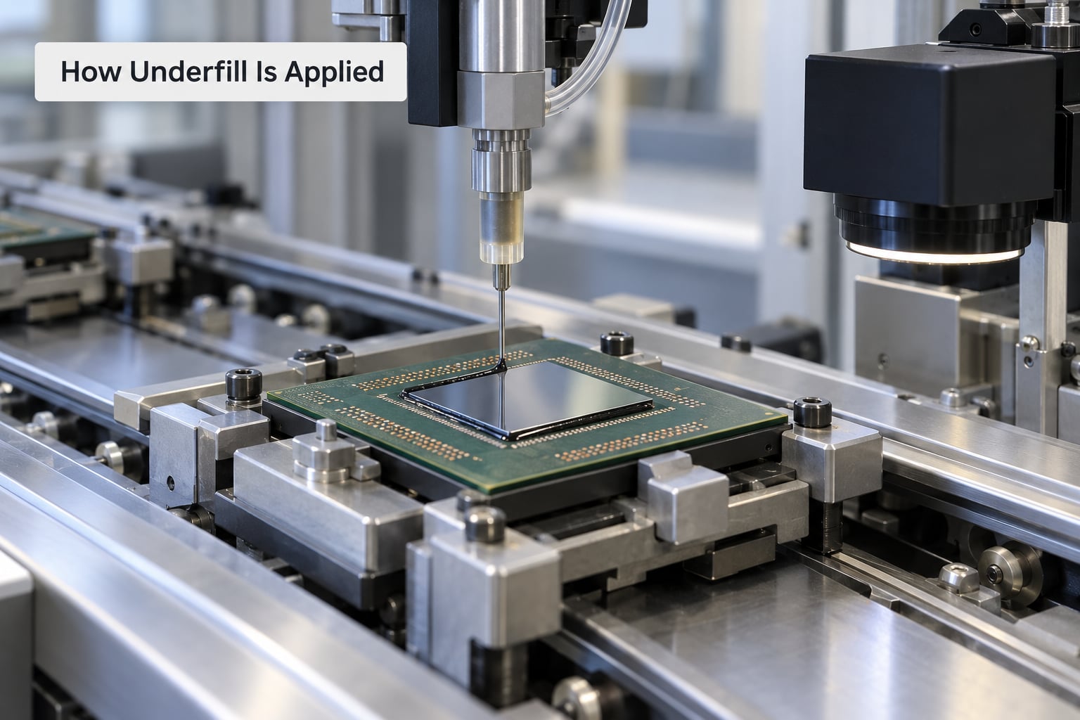
There are four ways to get resin into that gap, and the choice is driven by I/O density, die size and how much of the process you are willing to hand off to the resin supplier.
| Process | Sequence | Void tendency | Best fit |
|---|---|---|---|
| Capillary dispense | Reflow the joint first, then dispense and let the gap wick the resin in | Moderate; sensitive to residue and gap geometry | Large die, low to medium I/O, mature high-volume lines |
| No-flow underfill | Dispense onto the substrate, then place the die and reflow through the cure window | High without process control; solder-resin reaction drives it | Small die, lower I/O density, assembly lines without a separate underfill step |
| Molded underfill | Transfer-mould the resin around and under the chip in one step | Low if the mold is well vented | High I/O density, fine pitch, automated high volume |
| Wafer-level underfill | Deposit material on the wafer before assembly and laminate or cure in place | Low; no die-edge flow front at all | Fine-pitch Pb-free flip chip where die-edge flow would be slow |
For capillary dispense, the practical variables are well documented. Parts are typically preheated to 70 to 80 degrees Celsius before and during dispensing, which lowers viscosity and speeds the flow front. The needle sits about 0.003 to 0.008 inches away from the die side and slightly above the substrate, and a shot of 5 to 30 milligrams is placed one to three die edges out. Perimeter-bumped devices get a single bead along the longest free edge; array-bumped devices get an L-shaped line on two adjacent edges plus fillet material on the opposite sides.
Time and pressure valve pumps suit thin, fast shots, while auger and linear positive displacement pumps hold the more viscous filled materials that a pressure valve struggles with. Gravimetric closed-loop feedback on the pump is what keeps a viscous filler-loaded epoxy dispensing repeatably, because viscosity changes with temperature and with time in the syringe.
Two failure modes catch out new lines. Cross-capillary action happens when an underfilled neighbouring component pulls resin sideways and opens a void beside the die, which is why a pre-dispensed dam of higher-viscosity material is sometimes used as a barrier. And wherever a shield can sits over the die, the dispense has to reach the edge through a designed opening, which constrains both the pattern and the gap height.
What Controls Underfill Reliability?
Reliability comes down to whether the cured epoxy actually shares load with the bumps over the full die area. Several variables decide that, and they interact.
Material properties come first: CTE below Tg, the modulus of elasticity in the relevant temperature range, glass transition temperature and its shift with moisture, and fracture toughness. A low-modulus resin spreads strain better but supports the die less, and a resin whose Tg sits close to the assembly’s operating maximum behaves like a soft elastomer once humid. Filler settling during storage or shelf life can also leave the top of the gap resin-richer than intended, which is a local stiffness change right where the stress concentrates.
Geometry is the second group. Gap height, bump pitch, bump diameter, die size, edge keep-out and how close the nearest passive sits to the die edge all set the flow front’s job. Substrate choice matters too: a thin or low-modulus board flexes more under temperature cycling, and published data shows thicker substrate buys back roughly a factor of two in cycle life.
Process is the third. Cure profile has to match the material’s kinetics, and a part that is pulled before the resin has reached full cross-link density is weaker than any datasheet suggests. Voids and fillet quality are the visible results. The working rule of thumb is that the fillet should cover at least 70 percent of die thickness; too small a fillet means the die edge is unbraced, and too large one means the resin has spread past the die into a region it does not help.
Finally, how the board is handled after assembly matters. Underfilled parts are stiffer, not stronger in the ways that matter: bending the board during routing, depanelisation or connector insertion loads the die edge directly, and that edge is the least well-supported part of the package.
Common Underfill Defects and Failure Modes
Almost every underfill failure shows up first as a visual or X-ray symptom. Mapping the symptom back to its cause is the fastest route to a fix.
| Symptom | Likely root cause | Corrective action |
|---|---|---|
| Void in the centre of the gap | Entrained air, or a wave front that split and rejoined | Debubble the material, reduce dispense distance, reheat the part, slow the cure ramp |
| Void ring around a solder bump | Resin did not wet the bump surface, often from flux residue | Improve under-die cleaning or flux control, and check resin surface tension |
| Void at the die corner | Cross-capillary action from an adjacent component | Add a pre-dispensed dam or shift the dispense pattern away from the neighbour |
| Incomplete fill, resin stopped short | Gap too long, material too viscous, or substrate too cold | Raise the dispense temperature toward 80 degrees Celsius, or switch pump type |
| Resin on the die top surface | Pass height too high, so the flow front crested the die edge | Split into multiple passes, each staying below die height |
| Fillet too small or feathered | Low shot volume, or the edge was not heated evenly | Raise the shot into the 5 to 30 milligram window and check edge temperature |
| Delamination after humidity exposure | Poor wet-out, contamination, or a partially cured matrix | Verify cure state, check Tg shift with moisture, and re-qualify the surface prep |
| Cracked solder joint under cycling | Void adjacent to the joint removing local support | Hold void area within the specified acceptance limit and re-check fill geometry |
Solder-joint cracking is the failure that actually reaches the field. A void next to a bump does not itself carry load, so the bump takes the strain the epoxy was supposed to have shared, and the fatigue crack starts there.
How to Choose the Right Underfill
Selection works backwards from the failure you are trying to prevent, not forwards from a catalogue. Start with the package geometry and the environment, then narrow the chemistry.
Establish the die size, bump pitch and bump diameter first, because they set how long the flow front has to travel and whether capillary dispense is viable at all. Above roughly fine-pitch arrays, wafer-level or molded underfill usually displaces capillary dispense for exactly that reason. Next, write down the thermal cycling profile, the drop requirement and the maximum assembly and board temperature, since those fix the cure window and whether rework has to be possible at all.
Then check the material against that profile: CTE below Tg close to your substrate, a Tg with enough margin above the hottest operating point even after moisture loading, a modulus that suits the strain you need to redistribute, and a cure schedule that fits the thermal budget you already have. Confirm the storage and shelf-life behaviour of the specific lot, because filled epoxies drift in viscosity and can settle. Finally, size the process for the volume you actually build, since a line tuned for hundreds of units a week and one tuned for hundreds of thousands are different machines.
How do you calculate the volume of underfill needed?
Use gap volume plus seal volume minus bump volume. Gap volume is the die footprint times the gap height, seal volume covers the fillet and any dam material, and you subtract the space the solder bumps already occupy. In practice engineers add a dispensing tolerance on top of that figure and verify it by weighing a set of parts, since the calculation is only as good as the gap height assumption.
How Underfill Is Inspected and Tested
Inspection has two jobs: prove the gap is filled, and prove the resin is fully cured.
Visual inspection catches the gross cases: resin on the die top, a short fill, a missing or collapsed fillet, and obvious edge voids. X-ray is the standard non-destructive method for the gap itself, and modern digital radiography with a void analysis routine will return a void area percentage per die. The acceptance limit is usually stated as an area fraction of the gap that is not voided, following the solder-void approach in JEDEC JESD22-B117, and the specific limit is set by your own qualification rather than by the standard alone.
Scanning acoustic microscopy is used when the epoxy is well bonded acoustically, which gives a sensitive read on delamination. Computed tomography is slower but resolves three-dimensional void location, which is how you find a void trapped under the centre of a die rather than at an edge.
Cross-sectioning remains the final arbiter because it is the only method that shows the fillet geometry and the bump wetting directly. Cure state is checked on a sample rather than on every part, typically by glass transition temperature from a thermal scan or by measuring hardness.
Reliability qualification then does the real proving. Temperature cycling to JEDEC JESD22-A104, with the cycle extremes set to the application rather than to the standard default, is the test most often tied to underfill selection. Humidity exposure and biased testing expose moisture-driven delamination, and drop testing exposes the fillet and die-edge weaknesses that cycling never touches.
Frequently Asked Questions
What is underfill in welding?
In welding, an underfill is a groove along the side of the weld bead or at the toe of the joint where the weld metal did not fully fuse with the base metal. It is a welding defect. The flip chip underfill described here has nothing to do with it, despite the shared word.
What causes voids in flip chip underfill?
The three usual causes are entrained air, poor wetting, and cross-capillary action from a neighbouring component. Residue left on the substrate by flux is the most common underlying factor, because it blocks the resin from wetting the solder and the board. Cold substrates, viscous material and a long flow path make all three worse.
What is the difference between no-flow and capillary underfill?
Capillary underfill is dispensed after the solder has reflowed, and the resin wicks into the gap on its own. No-flow underfill is dispensed onto the substrate before die placement, then reflowed with the joint, so the resin has to melt and flow aside during the reflow. No-flow is faster but harder to control.
How do you calculate the volume of underfill needed?
Add the gap volume, which is die area times gap height, to the seal volume for the fillet and any dam, then subtract the volume the solder bumps already occupy. Add a dispensing tolerance and confirm the result by weighing sample parts, since the calculation depends on the gap height you assumed.
How long does underfill curing take?
It depends on the chemistry and the temperature. Common thermal schedules run a few minutes at around 150 degrees Celsius, while low-temperature formulations favour longer holds at lower temperatures to stay within a low-reflow budget. UV-cure acrylate systems are much faster but need line-of-sight to the gap.
Can you rework an underfilled flip chip?
Rarely. Once the epoxy cures, removing a die usually destroys the board, so an open joint is not repairable by reflow. That is the trade-off you accept for the stress redistribution and moisture sealing the underfill provides, and it should be weighed before the design is frozen.
Conclusion
Start by writing down the mechanical and thermal loads the package must survive, then pick a material whose CTE, Tg and modulus match that profile and your substrate. Qualify the dispense and cure on sample assemblies, and inspect the gap by X-ray and the fillet by cross-section before the line runs at volume. The material choice matters, but a perfectly specified epoxy dispensed on a cold, dirty substrate will still fail.