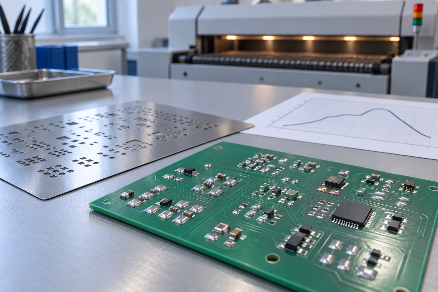
Reflow soldering is a manufacturing process that attaches one to thousands of tiny surface-mount components to a printed circuit board in a single heating pass. Solder paste, a mixture of powdered solder alloy and flux, is printed onto the board’s pads, the components are set into that paste, and the whole assembly is heated in a controlled temperature profile so the solder melts, wets both metal surfaces and freezes into a permanent joint.
That single-pass approach is why reflow exists. Soldering each part by hand, one joint at a time, is fine for a prototype and hopeless for a board carrying thousands of parts. Reflow treats the entire board as one workpiece and heats it the same way every time, which is what makes the joints inspectable and repeatable.
One thing worth clearing up early, because searchers often trip over it: reflow as a manufacturing process and reflow as a repair technique are two different things that share a word. Manufacturing reflow is paste plus placement plus a controlled oven profile. Repair reflow means reheating a joint that already exists on a board somebody else assembled. This guide covers the manufacturing process, and flags where repair differs.
(A third meaning of “reflow” belongs to web typography, where text reflows when a screen resizes. Unrelated to electronics, and not what this article is about.)
Table of Contents
- What Is Reflow Soldering?
- How Does Reflow Soldering Work?
- What Temperature Profile Does Reflow Use?
- What Happens to the Solder During Reflow?
- How Do You Reflow a PCB?
- What Are the Common Reflow Soldering Problems?
- Frequently Asked Questions
- What are the main types of reflow oven?
- Does leaded or lead-free solder need a different reflow temperature?
- Can I reflow solder with a heat gun?
- Can you reflow through-hole boards?
- Is hand soldering the same as reflow soldering?
- Conclusion
What Is Reflow Soldering?
Reflow soldering attaches surface-mount components to a printed circuit board by heating solder paste until it flows. The paste sits on the board’s copper pads, the components rest on top of it, and a controlled temperature ramp melts the alloy so it wets the pad and the component’s terminal, then solidifies into a mechanical and electrical bond.
Three things have to be present for the process to work at all:
- Solder paste — fine particles of solder alloy suspended in a flux vehicle, printed through a stainless steel stencil to put a controlled amount on each pad.
- Surface-mount components — chips, resistors, capacitors and packages whose terminals sit directly on the board surface rather than passing through holes in it.
- A controlled heat source — usually a multi-zone convection reflow oven that walks the assembly through a fixed temperature profile, with the peak set by the solder alloy and the ceiling set by the most heat-sensitive part on the board.
The word “reflow” comes from the fact that the deposited solder is remelted rather than applied as a molten stream. Before the paste reaches liquidus it just softens; above it, it reflows. Everything else in the process exists to make that remelt predictable.
Manufacturers use it because it scales. A pick-and-place machine can position tens of thousands of components per hour, and a single oven pass forms every joint on the board at once. Hand soldering simply does not have a comparable throughput, and it varies by operator.
How Does Reflow Soldering Work?
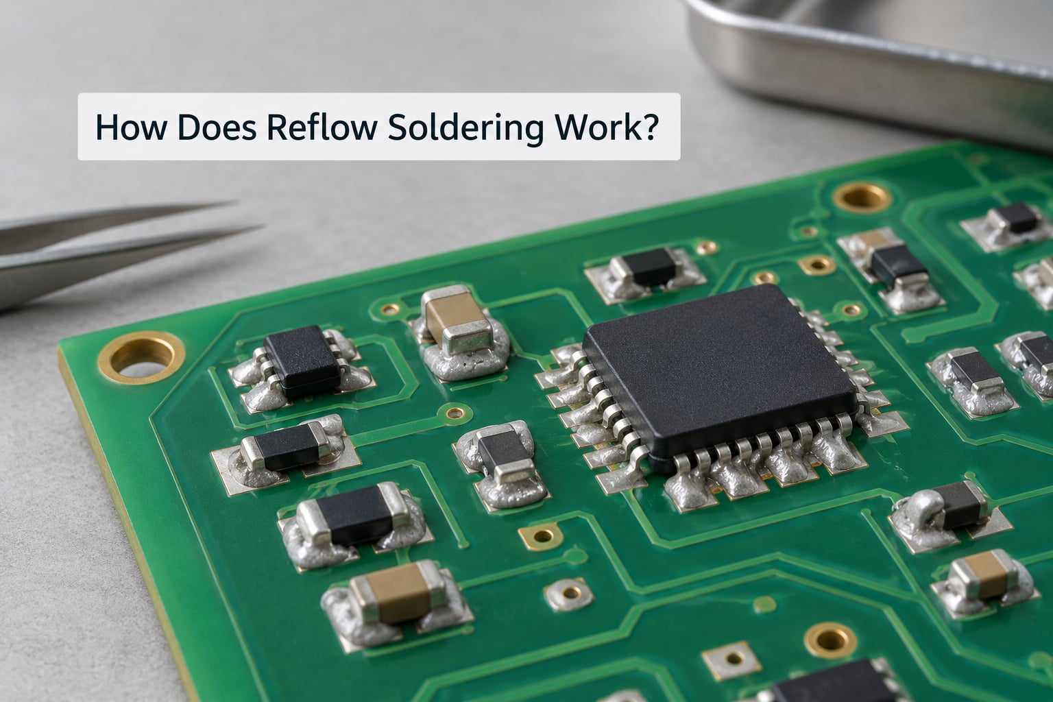
The full line has four steps. Two of them happen before anything is heated, which surprises people who assume solder and board go in together.
- Stencil printing. A stainless steel stencil, a thin sheet with apertures cut to match each pad, is aligned over the board and solder paste is pushed across it with a squeegee. Paste lands only where the apertures are, and the stencil lifts away leaving a controlled deposit on every pad.
- Placement. A pick-and-place machine picks each component from a feeder and places it into the paste. The paste is slightly tacky, so it holds the part in position for transport. If the part shifts on the way to the oven, that is a placement fault, not a heating fault.
- Reflow. The board enters a multi-zone oven where it passes through a preheat zone, a thermal soak zone, a reflow zone and a cooling zone. The flux activates, the alloy melts, and every joint on the board forms in the same pass.
- Cooling and inspection. Controlled cooling solidifies the joints, then the board is inspected. Visual and AOI inspection catch surface defects; X-ray catches voids hidden inside packages like BGAs.
Two properties of this flow are worth noting. The board sees one thermal history, not thousands of individual iron strokes, which is why package-level assemblies can be built at all. And the joint is formed once, in a few seconds above liquidus, rather than repeatedly reheated afterwards — repeated heating is what grows brittle intermetallic layers inside a joint.
What Temperature Profile Does Reflow Use?
A reflow profile is a time-versus-temperature curve, and every reflow oven is really just a machine for holding a board to that curve. The curve has four sections, and each one exists to stop a specific failure.
| Zone | Purpose | Target temperature | Target duration | Slope rate |
|---|---|---|---|---|
| Preheat | Bring the whole assembly up toward the process window evenly | Room temperature to roughly 150 °C | 60–120 seconds | Maximum about 3 °C/s |
| Thermal soak | Equalise temperature across the board and drive off solvent and moisture | 150–200 °C | 60–120 seconds | Held nearly flat |
| Reflow (peak) | Melt the alloy and form the joint | 20–40 °C above the alloy’s liquidus | 30–90 seconds above liquidus | Rise to peak, then hold |
| Cooling | Solidify the joint without thermal shock | Drop back through the solidification range | Until roughly 100 °C | About 2–4 °C/s |
The numbers in that table are ranges for a lead-free SAC305 process, not fixed targets. The exact profile comes from two documents: the solder paste manufacturer’s datasheet, which specifies the alloy’s liquidus and its required time above liquidus, and the datasheet of the lowest-temperature-rated component on the board, which sets the ceiling nobody is allowed to exceed.
Time above liquidus, usually shortened to TAL, is the number people get wrong most often. Most paste specifications call for at least 30 seconds of molten time, and staying under 60 seconds is a common target. Too little and the joint does not fully coalesce. Too much and you get excessive intermetallic growth and, on some boards, degraded packages.
Ramp rate is capped at roughly 3 °C/s for a reason. Heat a board faster than that and the surface heats faster than the core, which bends the board and can crack components outright. Beyond about 260 °C, internal dies inside surface-mount packages start to take damage, and intermetallic growth accelerates sharply.
A rule of thumb industrial lines run on: set the peak 20–40 °C above liquidus, and never more than about 5 °C below the maximum temperature rating of the most vulnerable component on the assembly. Then verify with a thermocouple. The oven setpoint is not the board temperature, and the gap between them is one of the most common sources of confusion for people new to the process.
What Happens to the Solder During Reflow?
This is the part industrial guides tend to skip and the part that actually explains the process. Four things happen, in this order, and each depends on the one before it.
Flux activation. Copper and the component terminals both carry an oxide layer, and molten solder will not bond to a dirty surface. The flux vehicle in the paste is designed to be inert until heated; in the preheat and soak zones it activates and strips those oxides away. It also carries moisture and solvent out of the deposit as it outgasses, which is why the soak zone exists.
Melting and coalescence. Above the liquidus temperature, the alloy particles in the paste become fully molten. Surface tension pulls the separate droplets together into one body of liquid solder per pad. The alloy matters here: SAC305 melts at around 217 °C, while a 63/37 tin-lead alloy is fully liquid at about 183 °C. A eutectic alloy like the 63/37 goes from solid to liquid at one temperature; a non-eutectic alloy like SAC305 has a range between solidus and liquidus, so it slumps before it flows.
Wetting. Clean molten solder spreads across clean metal and pulls itself into a concave fillet at the pad edge. That spreading is wetting, and IPC-A-610 treats an insufficiently wetted joint as a defect. Solder that beads up into a convex ball instead has not wetted the surface, and that bead shape is the single most useful visual signal a board gives you.
Solidification and intermetallic formation. A thin intermetallic compound layer forms at the boundary between the solder and the pad. A little of it is what makes the bond metallurgical and strong. Too much, from repeated reheating or a long time above liquidus, turns the joint brittle. Control the profile and this layer stays thin; neglect the profile and it becomes a failure that shows up months later under thermal cycling.
Compare two joints and the difference is obvious. On a sound joint the fillet is smooth, concave, and bright, with a clean boundary between solder and pad. On a cold joint the surface is dull and lumpy, the fillet looks convex or grainy, and the original joint boundary is still visible — a sign the solder melted and then moved without wetting properly. The cold joint will often pass a continuity check on the bench and still fail in the field, which is why IPC treats it as non-conforming rather than merely untidy.
How Do You Reflow a PCB?
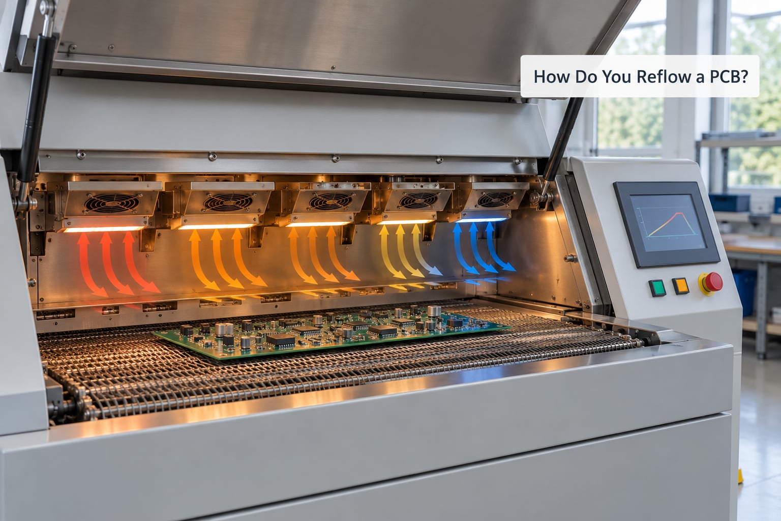
Here is the process at a working level. Specific temperatures belong to your paste and your component datasheets, not to this article.
- Prepare the board. Clean, dry, and inspect the bare PCB. Check the paste is the alloy and type you intend to use, and confirm the most heat-sensitive component on the assembly and its maximum temperature rating.
- Print the paste. Align the stencil to the board’s pad pattern, print, and inspect the deposit. Too little paste and you get insufficient solder; too much and you get bridging.
- Place the components. Seat each part into the paste without crushing it. Fine-pitch parts such as QFNs and BGAs need a placement accuracy the paste itself cannot rescue.
- Heat the assembly. Run the profile. On a production line this means loading a profiled board into a zoned oven. Under the profile in the previous section, the joint forms in seconds.
- Cool and inspect. Let the board cool in the oven’s cool-down zone, then inspect visually, by AOI, and by X-ray where packages hide their joints. Record the profile for the specific board and paste combination, and re-profile rather than reusing settings when either changes.
Heat-sensitive parts deserve a specific mention. Electrolytic capacitors, connectors, polymer fuses and some displays all have maximum temperature ratings well below what a lead-free profile reaches, and an electrolytic capacitor under excessive heat can burst. Profile the lowest-rated part first, then work within its limit.
Hobbyist methods exist and mostly work for prototyping. A convection toaster oven with a shelf is the closest to a real reflow oven and can produce sound joints on a small board, but it has no zone control, so temperature swings with whatever else is in the oven and the profile drifts. A hot air pen or heat gun gives local heating and works for rework and single joints, not for a board of several hundred parts. Neither approach meets the IPC-7530 profiling requirements, so treat the results as prototype quality rather than production quality. Work outdoors or with fume extraction, and never heat a board that still has bulk electrolytic capacitors fitted if you can remove them first.
On repair work, professionals use a controlled hot-air rework station with a profiled nozzle and a heated board underneath, which brings the whole assembly up to temperature evenly instead of blasting one joint. That is the same physics as an oven, with a much smaller footprint.
What Are the Common Reflow Soldering Problems?
Almost every reflow defect traces back to the profile, the paste deposit, or the placement step. Here is the mapping most useful when you are staring at a bad board.
| Defect | What you see | Root cause | Corrective action |
|---|---|---|---|
| Bridging | Solder connects two adjacent pads | Excess paste, low flux activity, or too long above liquidus | Reduce the deposit or use a higher-activity flux; check TAL |
| Insufficient solder | Joint does not fill the pad, visible pad corners | Too little paste, or a profile that never reaches liquidus | Increase stencil aperture or correct the peak temperature |
| Tombstoning | One end of a chip capacitor stands on end | Uneven wetting along the terminations | Improve soak time and ramp uniformity; check paste type |
| Cold joint | Dull, lumpy, convex joint with a visible boundary | Insufficient heat or time above liquidus | Re-profile and reflow; mechanically disturb and re-heat the joint |
| Insufficient wetting | Solder beads up instead of spreading | Oxide, contamination, or exhausted flux | Clean the pads, check flux activity, check TAL |
| Solder balling | Small loose balls scattered around pads | Oxide on the board, paste splatter, or excess wetting time | Clean the board, check the print and shorten time above liquidus |
| Voids | Cavities visible on X-ray, usually inside a package | Outgassing trapped under the part as it solidifies | Increase soak so volatiles clear before melting; consider a lower-solvent paste |
| Component damage | Cracked packages, burst capacitors | Peak temperature or soak time above the part’s rating | Re-profile against the lowest-rated component on the board |
Two questions come up constantly about the rows above. Will a cold solder joint still work? Sometimes, on a low-current path, which is exactly why it is dangerous: it passes a bench test and fails later under load or thermal cycling. And if solder balls up instead of flowing, the joint did not wet the surface, so there is no metallurgical bond to the pad — the connection is unreliable by definition, not by degree.
Frequently Asked Questions
What are the main types of reflow oven?
The three common types are forced-air convection, infrared, and vapor phase. Convection ovens heat the air around the board and are the most widely used because airflow gives good zone control. Infrared ovens heat components directly, which is fast but less even on large assemblies. Vapor phase ovens boil a liquid and condense it on the board, giving gentle and uniform heating at a higher equipment cost.
Does leaded or lead-free solder need a different reflow temperature?
Yes, and the difference is large. A 63/37 tin-lead alloy is fully liquid at about 183 °C, so its peak sits roughly 200–215 °C. SAC305, the common lead-free alloy, has a liquidus near 217 °C and typically peaks around 235–250 °C. Lead-free also needs a gentler ramp, because its higher melting point and slower wetting leave more opportunity to thermally shock the board.
Can I reflow solder with a heat gun?
You can, for rework and single joints, but not as a substitute for a reflow pass. A heat gun heats one area at a time and in an uncontrolled way, so adjacent parts can exceed their ratings while the joint itself sits below liquidus. It also gives you no profile to record or repeat. For new assembly, use an oven; for a single dead joint, a heat gun is a reasonable repair tool.
Can you reflow through-hole boards?
Yes, through a technique often called intrusive soldering. Through-hole joints are filled with solder paste or an equivalent, placed through the board so the paste is forced into the plated through-hole, and then heated like a normal reflow cycle. It is used where a board mixes surface-mount parts with a few through-hole connections, though conventional wave or hand soldering remains more common for the through-hole portion.
Is hand soldering the same as reflow soldering?
No. Hand soldering applies a molten iron tip to one joint at a time, so each joint gets its own, different heat history and its quality depends on the operator. Reflow forms every joint on a board in a single controlled pass, which is why it is repeatable and inspectable at volume. Hand soldering remains the practical choice for rework, prototypes, and through-hole connections.
Conclusion
Reflow soldering is controlled heating. Paste goes on the pads, components go into the paste, and a fixed time-versus-temperature profile melts the alloy, activates the flux, wets the surfaces and solidifies every joint on the board in one pass.
Your first move is the datasheets, not the oven. The solder paste datasheet gives you the alloy, the liquidus and the required time above liquidus; the lowest-temperature-rated component on the board gives you the ceiling. Then verify the profile with a thermocouple against IPC-7530, check joints against IPC-A-610, and remember that a new paste or a new board layout means a new profile rather than a copied setting.