An RC filter is a two-component circuit, one resistor and one capacitor, whose time constant RC sets the frequency where it starts attenuating. The rule is one line: fc = 1 / (2 pi R C). Series resistor, capacitor to ground, output across the cap, and you have a low-pass. Swap them and you have a high-pass.
I have built and measured enough of these to know where the theory stops matching the board. Below is the whole of rc filter design basics explained, in the order that actually helps: what the parts do, how to pick a corner frequency, how to choose R and C, and what loading and tolerance do to your numbers once parts are soldered.
If you are new to analog work, read straight through. If you are chasing a filter that does not behave, jump to the loading and lab sections.
Table of Contents
- What Is an RC Filter and Why Does It Work?
- The four main types of filters
- How to Choose the Cutoff Frequency With the fc Formula
- Common component combinations and what they give you
- What the response looks like at key frequencies
- Low-Pass RC Filters: Letting Low Frequencies Through
- High-Pass RC Filters: Letting High Frequencies Through
- How to Design an RC Filter for a Practical Signal
- RC Filter Design Basics Explained Through a Worked Example
- What Happens When the Load Changes the Filter?
- How to Check Your RC Filter in the Lab
- Common RC Filter Design Mistakes
- Frequently Asked Questions
- What is the basic formula for an RC filter cutoff frequency?
- How do I choose resistor and capacitor values for an RC low-pass filter?
- Does an RC filter have a sharp cutoff or a gradual roll-off?
- What is the difference between a first-order and second-order RC filter?
- Can I use any resistor and capacitor values in an RC filter?
- How do I verify that an RC filter is working correctly?
What Is an RC Filter and Why Does It Work?
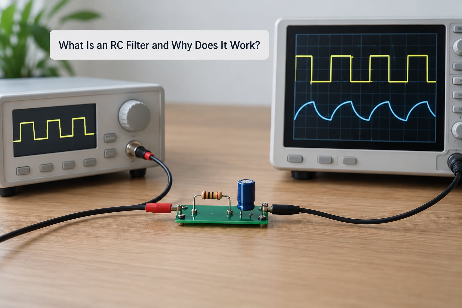
The reason a capacitor filters anything at all comes down to one fact: a capacitor’s impedance falls as frequency rises. That impedance is called capacitive reactance, written Xc = 1 / (2 pi f C). At DC and low frequencies the capacitor behaves nearly like an open circuit, so it carries almost no current. As frequency climbs, Xc drops, and the capacitor starts behaving more and more like a short to ground.
Put that capacitor in series with your signal and take the output across the resistor, and low frequencies see a path while high frequencies get shunted. Put the capacitor to ground after a series resistor and take the output across the capacitor, and the opposite happens: the resistor drops almost no voltage at low frequency, and the capacitor increasingly steals the signal at high frequency.
Those two arrangements are the low-pass and high-pass filter. Connect one of each in series and you get a band-pass. Wire a signal path and a frequency-selective bypass in parallel and you get a band-stop, sometimes called a notch filter.
The four main types of filters
Designers usually talk about filters in four families, and the names describe the passband rather than the parts used.
- Low-pass passes everything below the corner and rolls off above it. Anti-aliasing, sensor smoothing, rail noise rejection.
- High-pass passes everything above the corner and blocks the slow stuff. AC coupling, DC offset removal.
- Band-pass passes one range and blocks below and above. Cascaded high-pass then low-pass.
- Band-stop blocks one range and passes everything else. Notch filters, hum rejection at a known frequency.
A single resistor and capacitor only ever give you one of the first two. Anything more selective takes more parts, more poles, or a filter IC.
How to Choose the Cutoff Frequency With the fc Formula
The cutoff frequency, also called the corner frequency or the 3 dB point, is the frequency where a first-order filter’s output has dropped to 0.707 of the input, which is 3.01 dB in voltage terms and half the power. At that same frequency the output lags the input by exactly 45 degrees.
The formula, rearranged the three ways you will actually need it:
fc = 1 / (2 pi R C)
R = 1 / (2 pi fc C)
C = 1 / (2 pi fc R)
The time constant and the cutoff frequency are the same fact in two languages. Tau = RC is the time for the output to reach 63.2 percent of a step input, and fc = 1 / (2 pi tau). A 1 ms time constant gives you 159 Hz. This trips up a lot of people who compute tau, forget the 2 pi, and then wonder why their filter is off by a factor of six.
Common component combinations and what they give you
| Resistor | Capacitor | Tau = RC | Cutoff |
|---|---|---|---|
| 1 kOhm | 1 uF | 1 ms | 159 Hz |
| 10 kOhm | 100 nF | 1 ms | 159 Hz |
| 1 MOhm | 1 nF | 1 ms | 159 Hz |
| 2.2 kOhm | 100 nF | 220 us | 723 Hz |
| 10 kOhm | 10 nF | 100 us | 1.59 kHz |
| 1 kOhm | 100 nF | 100 us | 1.59 kHz |
| 4.7 kOhm | 33 nF | 155 us | 1.03 kHz |
| 10 kOhm | 1 uF | 10 ms | 15.9 Hz |
Notice the pattern: any pair with the same product gives the same corner. Choose the pair that suits the source impedance and the signal level rather than the one that looks prettiest on paper.
Below the corner, response is flat at 0 dB. Above it, the roll-off is 20 dB per decade, which is 6 dB per octave, and the gain follows the square root of 1 divided by 1 plus the frequency ratio squared.
What the response looks like at key frequencies
| Frequency | Low-pass gain | High-pass gain | What is happening |
|---|---|---|---|
| 0.1 x fc | 0.995 (about 0 dB) | 0.1 (about -20 dB) | Capacitor is effectively an open circuit, so the low-pass passes and the high-pass does not |
| fc | 0.707 (-3 dB) | 0.707 (-3 dB) | Capacitive reactance equals the resistance, phase lag is 45 degrees |
| 10 x fc | 0.1 (about -20 dB) | 0.995 (about 0 dB) | Capacitor is effectively a short to ground, so the roles swap |
| 100 x fc | 0.01 (about -40 dB) | about 1.0 (0 dB) | One decade past the corner, one more 20 dB gone |
Low-Pass RC Filters: Letting Low Frequencies Through
To build a passive rc low pass filter, put the resistor in series with the input, connect the capacitor from the output node to ground, and take the output across the capacitor. At DC the capacitor is open, no current flows, and there is no drop across the resistor, so the output sits at the input voltage. As frequency rises the capacitor starts pulling current, the resistor drops more voltage, and the output falls away.
This is the most common filter in electronics because it is almost always the right answer for a noisy signal. Put one in front of an ADC input to keep high-frequency content from folding back into your reading. Put one across a sensor output to knock down switching noise picked up on a long trace. Put one on a supply pin to pass the DC you want while shunting ripple to ground.
A supply bypass is the same circuit with a different name. On a mixed-signal board the decoupling capacitor in front of an analog section is a low-pass filter with a very high corner frequency, and its job is to keep switching currents on digital rails from pushing noise into the analog rails.
The one thing a low-pass never does is amplify. Gain is at most 1, and you lose signal above the corner. If you need gain as well as filtering, an op-amp stage follows.
High-Pass RC Filters: Letting High Frequencies Through
A high-pass uses the same two parts with the roles exchanged. The capacitor goes in series with the input, the resistor goes from the output node to ground, and you take the output across the resistor. At DC the capacitor blocks current entirely, so the output node is held at ground through the resistor. As frequency rises the capacitor’s reactance falls, current starts flowing, and the voltage across the resistor climbs toward the input.
The practical job here is DC blocking. Any sensor or amplifier output carries a small DC offset, and that offset can eat the bottom of your ADC range or push an op-amp into saturation. A series capacitor with a resistor to ground removes the offset and passes the AC signal on top of it. That is AC coupling, and it is why the coupling capacitor in an audio input path is sized against the lowest frequency you care about.
Worth internalising: the values that set a low-pass corner are the same values that set a high-pass corner with the same R and C. The only difference is which node you read the output from.
How to Design an RC Filter for a Practical Signal
Turn a vague requirement into parts in five steps. I use this order every time.
1. Write down the frequency in words. “Reduce noise above 5 kHz” is not a specification. “Attenuate everything above 1 kHz by at least 12 dB” is, because it tells you where the corner has to sit and how much slope you need past it.
2. Pick the corner from the ratio, not from the absolute number. If you need 12 dB of rejection at 5 kHz, and one first-order stage gives you 20 dB per decade, the corner must be a factor of two or more below 5 kHz, because each doubling of frequency past the corner buys 6 dB. Needing more than 6 dB per octave means cascading or moving to a second-order topology.
3. Choose C first, from the impedance it should present. The capacitor’s reactance at the corner frequency equals the resistor value, so pick C so that the resistance you want falls in a sane range for your source impedance. Electrolytics and large ceramics carry real ESR and ESL, so past roughly 10 kHz you want film or C0G parts. At audio and DC frequencies, 1 uF film or a good ceramic is comfortable.
4. Solve R, then snap to the E-series value you can actually buy. E96 gives 1 percent steps and plenty of choices, so your corner rarely lands exactly on target. Compute fc again with the value you are about to order and check the error is acceptable, usually within 5 percent.
5. Sanity-check the DC behaviour. Ask where the DC current goes. A series capacitor into a very high impedance node charges slowly and can shift your bias point. A series resistor feeding a biased node wastes current as a divider. Bypass capacitors and filters both bleed DC, so check your bias network still has the impedance it needs.
Two more items belong on the list: tolerance and temperature. A 5 percent resistor and a 5 percent capacitor put your corner about 10 percent out in either direction, because the errors multiply in the product. C0G ceramic and precision film resistors tighten that to well under 1 percent, and their temperature coefficients barely move the corner over a normal enclosure temperature range.
RC Filter Design Basics Explained Through a Worked Example
Here is a complete design, start to finish.
Requirement: a temperature sensor output must be sampled by a 12-bit ADC running at 1 kSPS. The sensor is quiet below 1 kHz and the board has switching noise above 5 kHz. Reject that switching noise by at least 12 dB before the converter sees it.
Step 1, corner frequency. One first-order stage gives 6 dB per octave. To get 12 dB at 5 kHz, put the corner two octaves down at 5 kHz / 4 = 1.25 kHz. Round to 1 kHz, which puts the rejection at 5 kHz comfortably above target.
Step 2, pick the capacitor. A sensor output is a high-impedance source, so keep the total series resistance in the 10 kOhm range to avoid loading it. With fc near 1 kHz, choosing C = 10 nF gives R = 1 / (2 pi x 1000 x 10e-9) = 15.9 kOhm. That is a workable number.
Step 3, snap to E96. The nearest 1 percent value is 15.8 kOhm, then 16.2 kOhm. Take 16.2 kOhm. Recompute: fc = 1 / (2 pi x 16200 x 10e-9) = 983 Hz. Close enough, and on the low side, which is what you want when the goal is rejection.
Step 4, verify the attenuation. At 5 kHz the frequency ratio is 5.09, so the gain is 1 divided by the square root of 1 plus 25.9, which is 0.194, or about 14.2 dB down. The requirement was 12 dB, so the design passes with margin.
Step 5, check the DC path. The 16.2 kOhm resistor sits in series with the sensor output. If the sensor needs a bias resistor to set its range, that resistor and this one form a divider. Include it in the calculation, or use an op-amp buffer ahead of the filter.
The same process for a high-pass: an audio input needs its 30 Hz rumble cornered off. Pick C = 1 uF, solve R = 1 / (2 pi x 30 x 1e-6) = 5.3 kOhm, snap to 5.1 kOhm, and recompute fc = 31.2 Hz. At 100 Hz the signal passes at 0.955 of the input, a loss of about 0.4 dB, which nothing in an audio chain will notice.
One more check on the worked low-pass: the sensor must be able to charge the capacitor. If the sensor can only source microamps, remember that a 10 nF capacitor against 16.2 kOhm has a 162 us time constant, and full settling to within 1 percent takes about five of those, or 810 us. Your 1 ms sample interval just barely allows it. Double the resistance and you halve the margin. Settling time and noise filtering are the same trade-off seen from two sides.
What Happens When the Load Changes the Filter?
This is where textbook filters meet real circuits, and it is the single biggest reason a filter that worked in theory misbehaves on the bench. The formula fc = 1 / (2 pi R C) assumes the resistor is the only resistance the capacitor sees. It never is.
Find the Thevenin resistance across the capacitor: look back from the capacitor terminals, replace the source with its output impedance, and treat the load resistor as a parallel path. For a low-pass that resistance is the series filter resistor plus the source impedance, all in parallel with the load.
Worked example. Nominal 10 kOhm and 100 nF, which the formula puts at 159 Hz. Now add a source with 1 kOhm of output impedance and a 10 kOhm load on the output. The resistance the capacitor sees is (1k + 10k) in parallel with 10k, which is 5.24 kOhm. The real corner is 1 / (2 pi x 5240 x 100e-9) = 304 Hz. Your 159 Hz filter is a 304 Hz filter, and every design margin you calculated against 159 Hz is wrong.
Three practical rules follow from this. First, if the load impedance is more than about ten times the filter resistance, ignore it and the formula is fine. If it is within ten times, include it. Second, a high input impedance like an op-amp or a FET gate barely loads anything, while a 50-ohm coax or a low-ohm ADC input loads heavily. Third, when loading matters and you cannot change the impedance, buffer the filter with an op-amp. That costs a part and buys back the whole design.
Capacitor parasitics matter less but still exist. Electrolytics can carry a few milliohms of ESR, and film capacitors in the nF range can add a few nanohenries of lead inductance, which shows up as a resonant bump well above the corner. Parasitic inductance in the resistor and PCB trace adds to that. If your filter has to behave predictably at megahertz, use C0G parts and keep the loop area small.
And the mirror-image problem: in a high-pass, the load resistor sits in parallel with the filter resistor, pulling the corner up. A 10 kOhm filter resistor with a 10 kOhm load is a 5 kOhm effective resistance, and the corner is twice where you computed.
How to Check Your RC Filter in the Lab
Bench verification takes about ten minutes and catches most of what goes wrong. This is the same workflow I use before a design goes to layout.
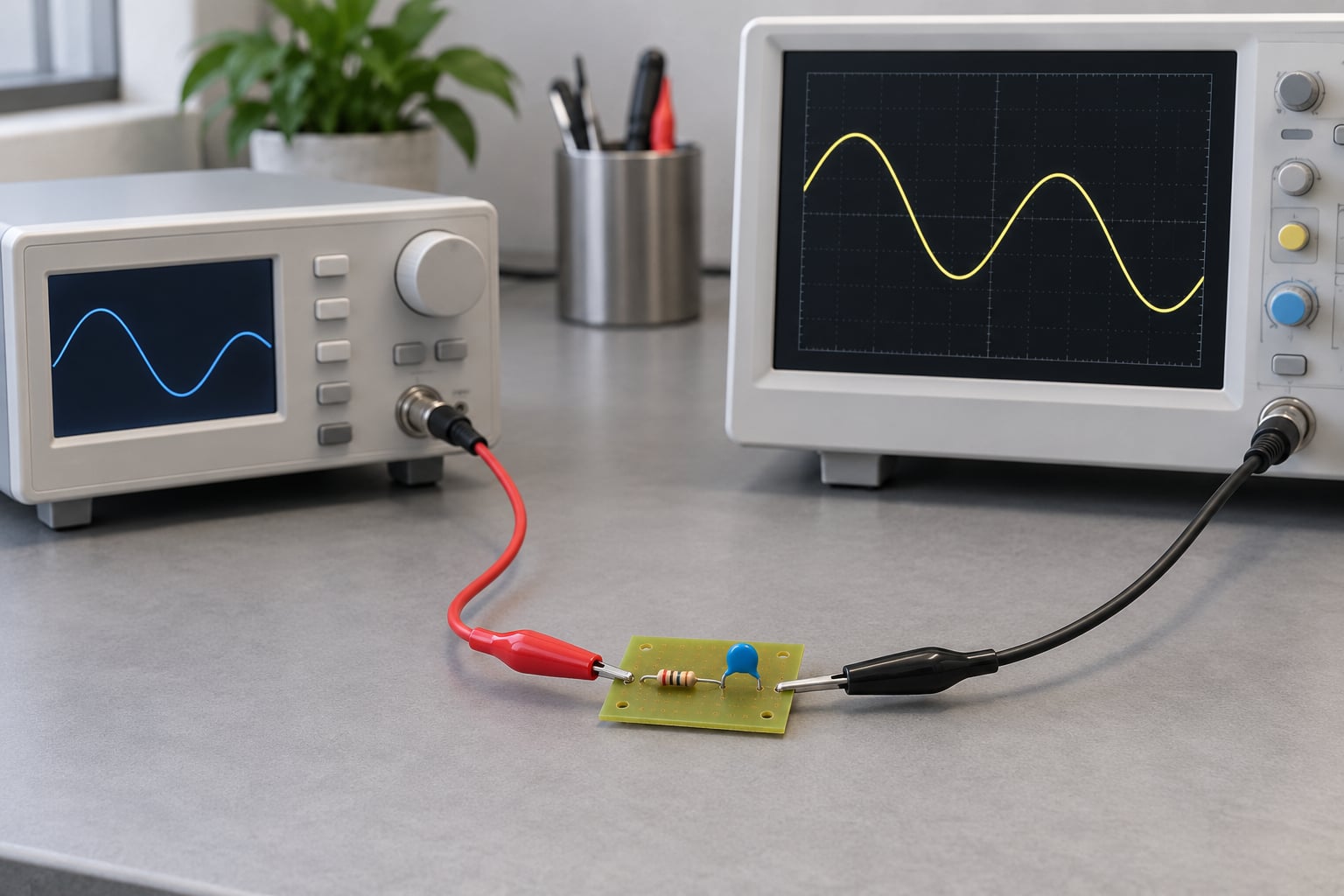
Set the generator to a 1 V peak sine at roughly 1 kHz, terminated properly, and connect the scope input across the capacitor of a low-pass. Confirm the generator amplitude at the board with the probe, since generator outputs and cable loading both make the actual input level different from the dial reading.
Sweep in decades, or at least in octave steps if you are in a hurry: 10 Hz, 100 Hz, 1 kHz, 10 kHz, 100 kHz. Record the peak-to-peak amplitude at each point. Plot it on log frequency, and the trace should be flat, then bending down through 0.707 of the passband level, then falling 20 dB for every factor of ten. If the slope is shallower than that, you are probably looking at a load or a probe issue. If it is steeper, something else is in the circuit.
Check the corner against your calculation. Measure the frequency where the amplitude is 0.707 of the passband, and compare it with 1 / (2 pi R C). A 20 to 30 percent discrepancy in the direction of a lower corner almost always means loading. A corner that is much higher than predicted means the capacitor value or the connection is wrong.
Watch the probe. A 1 MOhm scope input in parallel with a 10 kOhm filter resistor is a 1 percent error, which is usually fine, but on a 100 MOhm instrument node it is a 10:1 divider. Probe capacitance of 10 to 15 pF is negligible against 100 nF and dominant against 1 nF. Use a 10x probe rather than 1x for anything that is not a power rail, and use the ground spring instead of the clip lead, because that clip is an antenna and an inductor.
For anything tighter than a first-order passive response, measure with a network analyser or use a known-good reference. Scope amplitude readings off a low-amplitude tail get noisy long before the filter stops working.
Common RC Filter Design Mistakes
Taking the output from the wrong node. A low-pass and a high-pass with identical values differ only by where you measure. Series resistor, output across the cap, low-pass. Series cap, output across the resistor, high-pass. Check this before anything else when a filter passes the opposite band from what you expected.
Expecting a sharp cutoff. One RC stage rolls off at 20 dB per decade, which is gentle. A single stage is nowhere near enough anti-aliasing for a fast ADC, and often not enough noise rejection either. Cascading two identical first-order stages gives 40 dB per decade, but note the catch: two cascaded poles put the combined 3 dB point at 0.64 times the individual stage corner, so to keep a 1 kHz overall corner you set each stage to about 1.55 kHz. Cascaded passive stages also load each other, which is why a buffer between them makes the result predictable.
Ignoring tolerance in the product. The corner is proportional to the inverse of R times C, so two 5 percent parts give roughly 10 percent corner spread. Design against the worst case, or pay for 1 percent resistors and C0G capacitors where the corner actually matters.
Choosing extreme values. Very large resistors, 1 MOhm and up, turn sensor bias currents into offset errors and pick up noise. Very small resistors, 100 Ohm and below, load the source and waste power. Between roughly 1 kOhm and 100 kOhm covers most signal work. On a supply rail, 1 Ohm to 10 Ohm is the correct range and the loading question does not arise.
Confusing corner frequency with bandwidth on a second-order part. Butterworth, Bessel and Chebyshev filters all share the same schematic shape and differ only in the component values and the resulting peaking or Q. Copying values between them changes the response in ways the 3 dB number alone will not tell you.
Probing the circuit and changing it. A scope probe adds capacitance and resistance. If the filter stopped behaving correctly the moment you clipped the scope on, that is the finding, not a broken board. Use a high-impedance probe, a short ground spring, and check the numbers again with the probe attached.
Forgetting that a real ADC has a sampling capacitor. The track-and-hold cap in front of the converter looks like a switched load that dumps charge into your filter. Longer RC time constants make this worse, not better. Check the datasheet acquisition window before you set the corner.
Frequently Asked Questions
What is the basic formula for an RC filter cutoff frequency?
The cutoff frequency of a first-order RC filter is fc = 1 / (2 pi R C), where R is the series resistance and C is the capacitance. Solve it backwards when you know the target corner: R = 1 / (2 pi fc C) or C = 1 / (2 pi fc R). The time constant tau = RC is the same fact, since fc = 1 / (2 pi tau).
How do I choose resistor and capacitor values for an RC low-pass filter?
Choose the capacitor first so the resistance you solve for suits your source impedance, then compute R = 1 / (2 pi fc C) and snap to the nearest E-series value. Recompute fc with the value you will actually buy to confirm the error is acceptable. Keep the series resistance high enough not to load the source and low enough that the capacitor settles within your sampling interval.
Does an RC filter have a sharp cutoff or a gradual roll-off?
Gradual, by design. A single first-order RC stage falls at 20 dB per decade, or 6 dB per octave, so it is 3 dB down at the corner and 20 dB down one decade above it. Getting a steeper wall needs more poles: two cascaded stages give 40 dB per decade, and second-order active filters do the same in one stage.
What is the difference between a first-order and second-order RC filter?
Order means the number of independent reactive elements, and it sets how fast attenuation climbs. A first-order filter rolls off at 20 dB per decade and shifts phase by 45 degrees at its corner. A second-order filter rolls off at 40 dB per decade, can be tuned for a maximally flat passband or a sharper transition, and needs either two buffered RC stages or an op-amp.
Can I use any resistor and capacitor values in an RC filter?
Not quite. Very high resistances turn bias currents into offset errors and pick up noise, while very low ones load the source and waste power. 1 kOhm to 100 kOhm suits most signal work. For capacitors, watch ESR and ESL in electrolytics, and remember every part has parasitic inductance that shows up as peaking near or above the corner.
How do I verify that an RC filter is working correctly?
Drive it with a sine from a signal generator at a known amplitude and probe the output with a scope, measuring amplitude at 10 Hz, 100 Hz, 1 kHz, 10 kHz and 100 kHz. Find the frequency where the output is 0.707 of the passband level and compare it with 1 / (2 pi R C). A corner lower than predicted points to loading from the source or the load.
Start with the corner frequency, not the parts. Write down the frequency where the signal must be 0.707 of its passband level, choose the capacitor that gives you a sensible resistance, solve for R, and snap to a real value. Then check loading, because that is the variable that decides whether your bench result matches the calculation.
None of this has changed in 2026, and it will not, because two components and a time constant do not age. The engineers who get the most out of it are the ones who measure rather than assume.