Here is how heat is removed from modern processors: it leaves through a chain of touching parts. It conducts out of the silicon die into the thermal interface material and the integrated heat spreader, spreads across a heat sink, heat pipe or liquid cold plate, and is finally carried into the room by airflow or circulating coolant. Nothing along the way destroys the energy; each stage only moves it a little further and a little faster.
That answer sounds simple until you look at the numbers. A modern desktop part at full load pushes roughly 0.3 to 0.5 watts out of every square millimetre of die. A server accelerator manages several times that. The air in the room is the only place the energy can ultimately go, and air is a poor conductor, so almost all of the engineering goes into shaping the path between the transistor and that last, unavoidable step.
I see the same argument on forum threads over and over, and it always starts the same way: someone says a heat sink absorbs heat, so it must fill up and stop working. It does not absorb anything. It conducts and spreads, then hands the energy to moving air or coolant, which carries it out of the machine.
Table of Contents
- Why Modern Processors Generate So Much Heat
- The Processor Heat Transfer Chain
- How Heat Moves by Conduction
- How Heat Is Removed from Modern Processors at the Die
- What Thermal Interface Materials Do
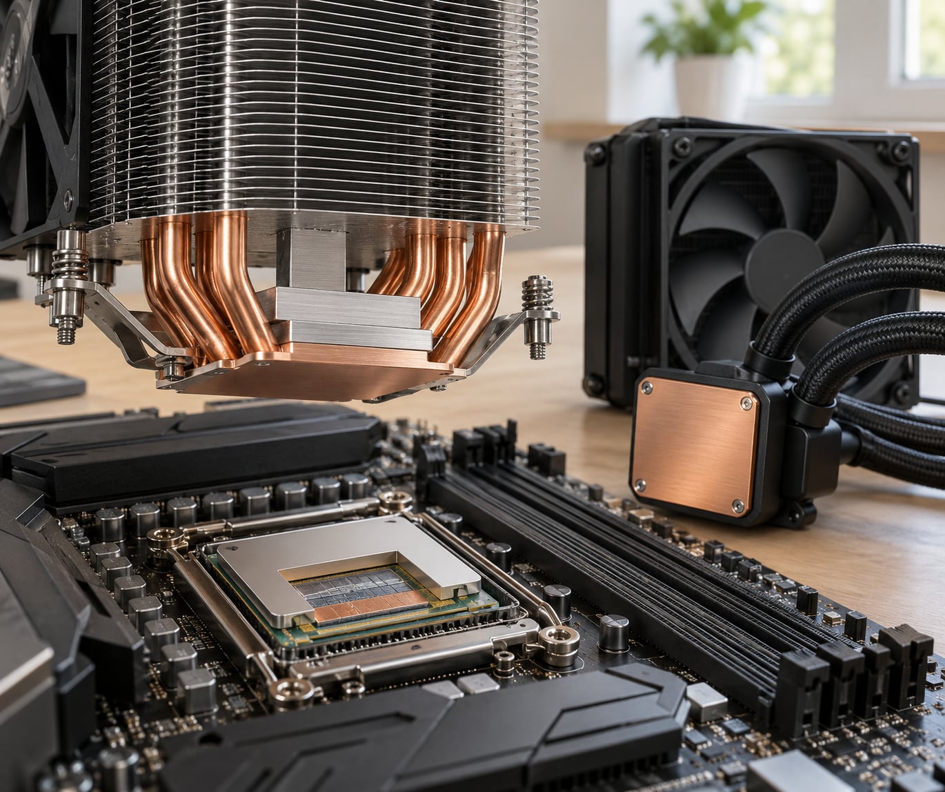
- How Heat Is Removed by Air Cooling
- How Liquid Cooling Removes Processor Heat
- Heat Spreaders and Vapor Chambers
- How Power Controls Reduce the Heat Load
- Why Server Processors Use Complex Cooling Systems
- Which Processor Cooling Method Works Best?
- Thermal Resistance and Temperature Problems
- Frequently Asked Questions
- Why do modern processors need active cooling?
- Does liquid ever cool the transistor layers inside a processor?
- Can more thermal paste make a processor run cooler?
- What happens when a processor thermal throttles?
- Do GPUs use the same heat-removal methods as CPUs?
- Start With the Full Heat Path
Why Modern Processors Generate So Much Heat
Every transistor that flips its state draws a charge from the power rail and puts it somewhere else when it flips back. That charging and discharging cycle dissipates energy as heat, and the amount is described by a simple relationship: power equals capacitance times voltage squared times frequency.
The squared term is what people miss. Dropping voltage from 1.2 volts to 0.9 volts cuts dynamic power by about 44 percent, while dropping frequency by a quarter cuts power by the same quarter. Designers have pushed voltage down hard for decades, which is why efficiency-per-watt improved even as absolute power climbed.
Leakage rides on top of all that. A transistor sitting idle still draws current, and as threshold voltages were lowered to hit power targets, static leakage grew into a real share of package power. Nothing about leakage computes anything useful.
Power density is the number that actually constrains design. When core counts doubled but the package area barely grew, watts per square millimetre doubled with them. That is the wall designers call power density scaling, and it is why a chiplet approach spreads hot parts across a larger substrate instead of crowding them onto one rectangle.
The practical result: useful computation is a minority of the energy going in. The rest becomes heat that a chain of interfaces has to carry away before the silicon slows down or fails.
The Processor Heat Transfer Chain
Heat follows one route, and each joint on that route is a thermal resistance. Adding resistance anywhere slows the whole path, because the same power has to flow through every stage in series.
| Stage | Part | Job | Dominant mode |
|---|---|---|---|
| 1 | Silicon die | Where the heat is generated, in uneven hot spots | Conduction |
| 2 | Thermal interface material | Fills microscopic gaps between die and lid | Conduction |
| 3 | Integrated heat spreader or lid | Pulls heat off small areas and spreads it wide | Conduction |
| 4 | Package substrate | Carries heat and power out to the board | Conduction |
| 5 | Heat sink or cold plate | Multiplies surface area, moves heat into air or fluid | Convection |
| 6 | Fan or pump | Keeps air or coolant moving over that surface | Forced convection |
| 7 | Room air | The final sink for the energy | Convection and radiation |
Radiation is the stage people conflate with the others. Below roughly 100 degrees Celsius a silicon package radiates a small fraction of its heat compared with convection, so it barely matters in a desktop or a laptop. It becomes relevant only for very hot surfaces such as exhaust air or a glowing element.
How Heat Moves by Conduction
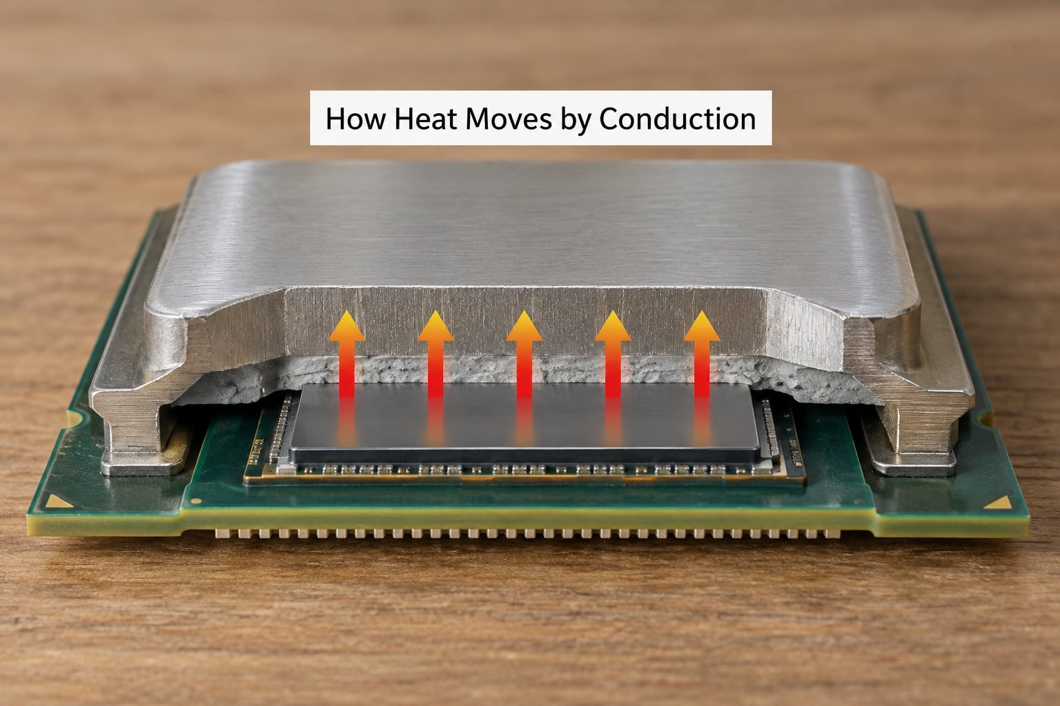
Conduction is heat moving through a solid by molecular vibration. Copper does it roughly twenty times better than silicon, which is why the metal lid matters so much even though the lid is not the source of the heat.
The physics of a fixed-power part is easier to reason about as an electrical analogy. Power is current, temperature difference is voltage, and thermal resistance in degrees Celsius per watt is the resistor. So the temperature rise across any element equals the power flowing through it times that element’s resistance.
Worked through: a 250-watt package sitting on a cold plate whose junction-to-ambient resistance is 0.12 degrees Celsius per watt lands about 30 degrees Celsius above the room. Add a second 0.06 in the interface and you are at 45 degrees of rise before ambient is even counted. The interfaces are often the bigger half of the problem, which is why contact quality matters more than the sink’s brand.
Two interface problems dominate. Flatness deviations leave air pockets, and air conducts roughly twenty-four times worse than a good thermal compound. And the mounting clamp has to press hard enough to squeeze the compound out of those pockets without cracking the package or loading the board unevenly.
How Heat Is Removed from Modern Processors at the Die
The die is where heat is made, and it is made unevenly. One core running an integer workload can run tens of degrees hotter than the idle cores beside it, so the processor engineers start at the die with two problems: local generation, and getting that heat sideways before it reaches a thermal interface.
In-die heat spreading is the first tool. Metal fill between active areas, plus a thermal interface path through the top of each core, pulls a local hot spot outward into cooler silicon. Above that, the package stack handles the rest: silicon die, die attach material, organic or silicon interposer, substrate, and the lid.
That lid is a deliberate design decision, not decoration. Copper conducts heat far better than the substrate, and it also spreads a concentrated hot spot across the whole lid footprint so the cooler above sees a broad, even warm surface rather than one point. The lid also needs a flat, stable surface for the cooler to press against, and it mechanically protects the fragile die during handling and socket insertion.
Chiplets pushed this logic further. Each die is small enough to spread heat comfortably, and the thermal engineer can assign the cooler parts of the package to the hot cores. The cost is that interconnects and thermal design now have to survive being split across multiple dies, which is a real constraint on stacked memory next to compute.
The key point: no cooler, however uniform, removes local temperature differences. A flat cold plate over a die with one hot core still leaves that core running hotter than its neighbours. Spreading has to happen inside the package.
What Thermal Interface Materials Do
Two flat surfaces touch only at microscopic peaks. A thermal interface material fills the valleys so heat can conduct across the full contact area instead of hopping through air. That is the entire job, and it is a bigger job than most people expect.
| Material | Form | Performance | Installation | Durability | Repairable |
|---|---|---|---|---|---|
| Thermal grease | Paste | High, widely spread | Easy, thin coat | Can dry or pump out over cycles | Yes |
| Thermal pad | Preformed sheet | Moderate | Easy, thickness sensitive | Long-lasting if undamaged | Yes |
| Solder TIM | Reflowed metal | Very high | Factory or specialist work | Excellent | No |
| Direct bonded copper | Fused plate | Highest | Specialist work | Excellent | No |
What a TIM does not do is move heat, cool anything, or fix a cooler that is too small. Once the compound is applied, the remaining thermal budget sits in the rest of the path.
That is why enthusiasts who delid a processor report real gains. Removing the factory lid and its bond removes a permanent soldered interface from the series, and the exposed die can be contacted directly. It also voids most warranties and demands precise handling of a part measured in fractions of a millimetre.
More paste is not better. Once the gaps are filled, extra compound only adds a thicker, less even layer that can spread heat sideways before it reaches the lid, and thick applications pump out during repeated cold cycles.
How Heat Is Removed by Air Cooling
A heat sink is a surface area multiplier with a metal base. A flat plate the size of a coaster might present a few hundred square millimetres; the same plate cut into fins can present tens of thousands. Convection scales with area, so more area means more heat can leave per degree of temperature difference.
Fins are not free. Each one blocks a little airflow, so dense fins need air with enough momentum behind it. A fan’s job is to create static pressure, not just volume. Push air through a radiator or a dense tower and pressure matters far more than how many cubic feet per minute the label claims.
Past a point, adding fins stops helping. Once the air is already moving as fast as it can through the gaps, extra surface just raises the pressure the fan has to fight. Base thickness then becomes the limit: a base too thin or too uneven conducts poorly into the fins no matter how many you stack.
Case airflow decides whether any of it works. Coolers pull air through themselves and dump it, so a restrictive filter or a solid panel behind the intake turns the machine into a recirculating box. Intake filters rated around 2.0 mmH2O of static pressure and radiator positions around 1.5 mmH2O are reasonable minimum targets for a build that matters.
Noise closes the argument. Fans that spin harder to overcome resistance are also louder, which is why fan curves matter as much as any cooler choice, and why a well-tuned mid-range tower can match a large cooler in a real chassis.
How Liquid Cooling Removes Processor Heat
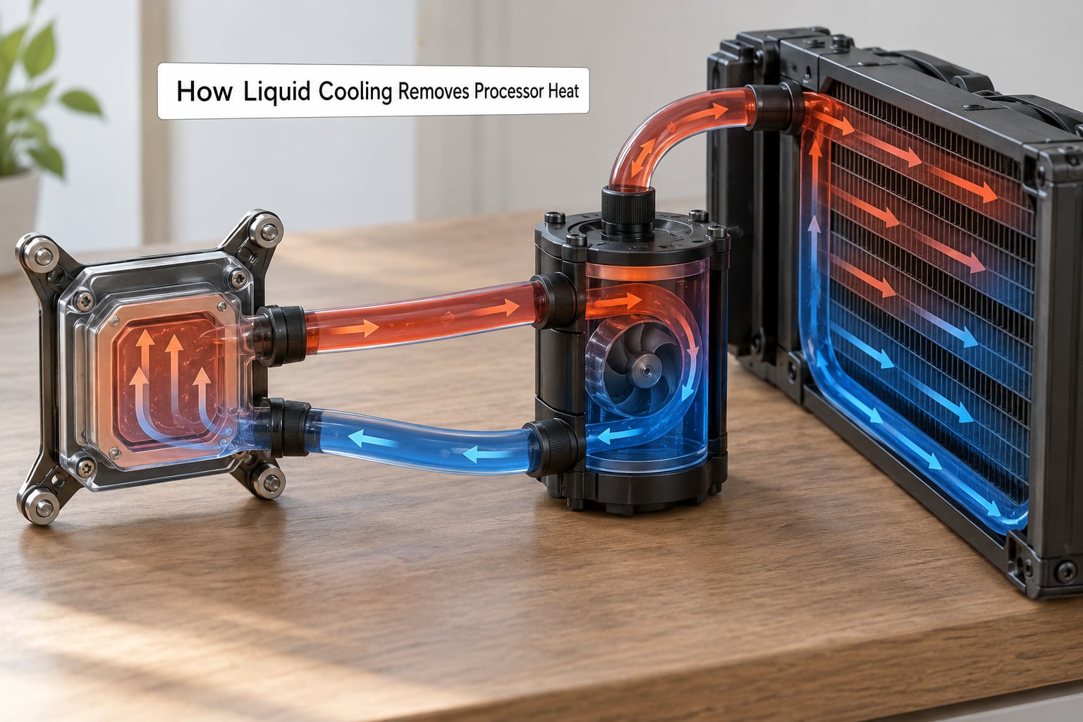
Liquid cooling replaces air’s low heat capacity with water’s, roughly 4000 joules per kilogram per degree against about 1000 for air. A cold plate with internal channels takes heat from the lid by conduction, and the coolant carries it to a radiator where fans return the energy to the room.
A closed loop has five working parts. The cold plate sits on the package, the pump drives flow through it, tubing carries coolant to and from the block, the radiator rejects heat to room air, and a reservoir buffers pressure and volume. Some units also run a small pump on the radiator itself.
Flow rate matters less than people assume. Any loop that is not airlocked moves heat by convection at the plate, and beyond modest flow the radiator and the plate’s internal channel design take over as the limiting steps. What does matter is keeping air out of the block, because a bubble in the channel collapses the flow locally.
Closed loop, direct-to-chip, and immersion are different designs with different goals. A desktop closed loop is convenience and appearance. Direct-to-chip means a cold plate mounted on the processor inside a server chassis, with facility water or a coolant distribution unit feeding it, and it has moved from experiment to default in new data-center parts. Immersion puts the whole board in a dielectric fluid, which handles very high rack densities and removes fans from the server entirely.
That is the general shape of how heat is removed from modern processors when air stops keeping up: move the fluid instead of just adding more metal.
Heat Spreaders and Vapor Chambers
A plain copper lid spreads by conduction alone, which means the far corners stay warmer than the centre. A vapor chamber replaces most of the solid interior with a sealed liquid and a wick structure, and the liquid boils at the hot spot and condenses at the cooler edges in a continuous loop.
Latent heat of vaporisation does the work here. Water carries a large amount of energy per degree during phase change, so the chamber moves heat across its surface almost isothermally. The result is a base that feels near-uniform across its whole footprint, which is exactly what a wide cold plate or a big fin stack wants underneath.
Heat pipes are the single-element version of the same idea. A sealed tube with a wick and a working fluid transports heat from an evaporator end to a condenser end, usually from a die to a fin stack mounted above the socket, which frees up case clearance.
Compared with a base-only cooler, a vapor chamber lets you shrink the fin stack while keeping or improving performance. It does not remove the need for a sink, though. Something still has to reject the energy to air, and the vapor chamber only makes the hand-off smarter.
How Power Controls Reduce the Heat Load
Frequency, voltage and power limits are the second half of processor thermal management, and they act on generation rather than removal. Nothing here moves heat that already exists; the goal is to not make it in the first place.
Processors run at their power limit almost all the time, whether the workload wants that much speed or not. When a boosted core hits the ceiling, the controller trades clock speed for temperature. Heavy vector and matrix workloads, which consume far more power per operation than ordinary integer code, push cores into a lower frequency bin for the duration.
Thermal throttling is the backstop behind that. When junction temperature approaches the maximum junction rating, typically around 95 to 100 degrees Celsius on current desktop parts, the clock drops until heat generation falls below what the cooler can remove. You lose performance, and the machine feels it, but nothing is damaged.
Load and voltage behaviour matter too. A loop that never lets a core fall to a low voltage state draws more power at idle than it needs to, which shows up as a warmer machine and a busier fan in a room that should be cool.
Why Server Processors Use Complex Cooling Systems
A server part stacks complications a desktop chip does not have: many cores running continuously, high-bandwidth memory sitting right next to the compute die, a multi-phase voltage regulator next to both, and in an accelerator card, memory and power delivery in the same few square centimetres.
The power density is the deciding factor. Because accelerator boards approach several kilowatts per card and rack rows pack dozens of boards together, air moving through a chassis can no longer keep up. Direct-to-chip cold plates became the default for a simple reason: liquid carries far more heat per degree than air, and it reaches the die directly instead of through a sink.
Facility water then does the same job again at rack scale. A coolant distribution unit feeds cold plates, or a rear-door heat exchanger absorbs the hot exhaust before it reaches the room, or the board sits in an immersion tank. Every rack still ends with heat in the facility coolant or the room air, so the heat only moves one stage further out.
Core counts stall at thermal and power limits for exactly this reason. Adding cores means adding watts in a fixed footprint, and once cooling cannot absorb the extra heat, the part throttles instead of running faster.
Which Processor Cooling Method Works Best?
There is no universal winner, because the constraint moves with form factor. Phone, laptop, desktop and server parts have different power densities, so the sensible answer changes every time.
| Method | Transfer efficiency | Heat capacity handled | Complexity | Noise | Maintenance | Best fit |
|---|---|---|---|---|---|---|
| Air cooler, aluminium fins | Moderate | Low to moderate | Low | Fan noise | None | Mainstream desktops |
| Air cooler, all-metal tower | High for air | Moderate to high | Low | Fan noise | None | Powerful desktop chips |
| Heat pipe or vapor chamber | High across the base | Moderate | Low | Fan noise | None | Laptops and thin builds |
| Closed loop liquid cooling | High | High | Moderate | Pump and fan | Seals and pump life | Enthusiast desktops |
| Direct-to-chip cold plate | Very high | Very high | High, needs facility loop | Chassis fans only | Rack and loop service | Servers and accelerators |
| Immersion | Very high | Very high | Very high | Near silent | Fluid handling and service | Dense racks and HPC |
Pick the method that matches the densest part in the machine and the room it sits in. Anything beyond that is budget spent in the wrong place.
Thermal Resistance and Temperature Problems
Thermal resistance in degrees Celsius per watt is the number that ties a cooler to its performance. Junction-to-ambient resistance includes everything from the die out to the room, which is why a cooler and a case are really one system.
A useful reference set for a current desktop part, measured in a typical room:
| State | Package temperature | Fahrenheit |
|---|---|---|
| Idle | 30 to 45 degrees Celsius | 86 to 113 F |
| Light load | 50 to 65 degrees Celsius | 122 to 149 F |
| Sustained heavy load | 65 to 85 degrees Celsius | 149 to 185 F |
| Throttle onset | 95 to 100 degrees Celsius | 203 to 212 F |
| Maximum junction spec | 100 to 110 degrees Celsius | 212 to 230 F |
So 72 degrees Celsius is not a problem. That figure sits inside the normal heavy-load band, and it is 140 degrees Fahrenheit, which sounds alarming only because the scale changes.
Ambient sets the floor. As a rough rule for a desktop part, every 1 degree Celsius the room temperature rises adds about 0.5 to 0.7 degrees Celsius to the package, because the air is the final sink for the entire chain.
When a machine runs hotter than it should, work down the resistance series rather than reaching for a bigger cooler. An undersized cold plate or sink caps how much you can ever remove. Poor mounting pressure or a dried-out interface adds resistance exactly where the margin is thinnest. Blocked airflow, a failed fan or a failing pump prevents the last stage from working at all, and recirculation inside the chassis quietly undoes any good the cooler does.
Common high-temperature causes, roughly in order of how often they turn out to be the problem: a case filter or panel restricting intake, dried thermal compound, a cooler mounted with insufficient clamping force, ambient heat from a nearby exhaust or a poorly ventilated room, a fan that has slowed with age, and finally a heat sink that was undersized for the part from day one.
Frequently Asked Questions
Why do modern processors need active cooling?
Because a working transistor produces far more heat than passive surfaces can reject at the power densities modern silicon reaches. A fan or pump is the active element that keeps air or coolant moving so convection can keep pace with generation. Without it, the part hits its maximum junction rating within seconds and shuts down to protect itself. Passive designs work at far lower power densities.
Does liquid ever cool the transistor layers inside a processor?
Not inside the silicon itself. Cooling liquid never touches the transistor layers, because the junction has to stay dry and sealed. What liquid touches is a cold plate mounted against the package lid or die, directly on some server parts. In-package and on-die solutions do circulate fluid, but through channels built into the package rather than over the active transistors.
Can more thermal paste make a processor run cooler?
No. Once the microscopic gaps between die and lid are filled, extra paste adds nothing but a thicker, uneven layer that can spread heat sideways before it reaches the lid. Thin and even is the goal. Heavy application also pumps out over repeated cold cycles, which is a common cause of a machine that used to run cooler and now does not.
What happens when a processor thermal throttles?
Junction temperature approaches the maximum junction rating, usually around 95 to 100 degrees Celsius on current desktop parts, and the processor drops its clock frequency until heat generation falls below what the cooler can remove. Performance drops with it, most noticeably in games and sustained compiles. Nothing is damaged, and temperatures usually recover within seconds of the load easing.
Do GPUs use the same heat-removal methods as CPUs?
Yes, the physics is identical: conduction through interface and spreader, then convection into air or coolant. The difference is scale. A GPU has far larger die area and higher sustained power density, so it leans harder on vapor chambers, multi-fan coolers and, in data-centre cards, direct-to-chip liquid cold plates. The physics is the same, the design constraints are not.
Start With the Full Heat Path
If you are diagnosing a machine or designing one, start at the transistor and work outward to the room, treating the whole system as one series of thermal resistances. Locate where heat is actually generated, name every interface between that point and the air, and find the highest resistance in the chain.
Fix that one stage before adding cooling capacity. More fins will not help across a dried interface, a faster pump will not help behind a blocked intake, and a bigger cold plate will not help if recirculation keeps sending warm air back. The chain only gets as strong as its weakest joint, and every watt that enters must leave.
Lastly, remember that power controls are part of the same system. Voltage, frequency and power limits decide how much heat exists to remove, which makes frequency and voltage behaviour a thermal tool as much as a performance one.