Mechanical contacts do not close once. When two metal surfaces meet, the springy leaves bounce against each other for a few milliseconds and the pin sees a burst of edges instead of one. That is contact bounce, and debouncing is how you turn the burst back into a single event.
How to debounce a switch in hardware and software comes down to one idea: make sure the signal is genuinely steady before you accept it as a change. In hardware you slow the edge down with an RC filter and clean it up with a Schmitt trigger. In firmware you ignore every transition until the input has held the same value for a set interval.
The symptoms show up long before anyone searches for the cause:
- A menu cursor jumps two or three positions on one key press.
- A parts counter increments 18 times for 20 items.
- A relay clicks twice and the machine reverses direction unexpectedly.
- One button press occasionally toggles a channel off instead of on.
Below is the full path: what you need on the bench, both implementation routes, how to pick a debounce interval, how to verify the result, and the mistakes that keep this bug alive for months.
Table of Contents
- What You Need
- Step-by-Step: How to Debounce a Switch in Hardware and Software
- How to Debounce a Switch in Hardware
- How to Debounce a Switch in Software
- Choose the Debounce Delay
- Test and Tune the Implementation
- Common Mistakes
- Frequently Asked Questions
- How can I debounce a switch using Arduino code?
- What is a switch debouncer?
- What is the best debounce time?
- What is debouncing vs. throttling?
- Is an RC filter alone enough to debounce a switch?
- Conclusion
What You Need
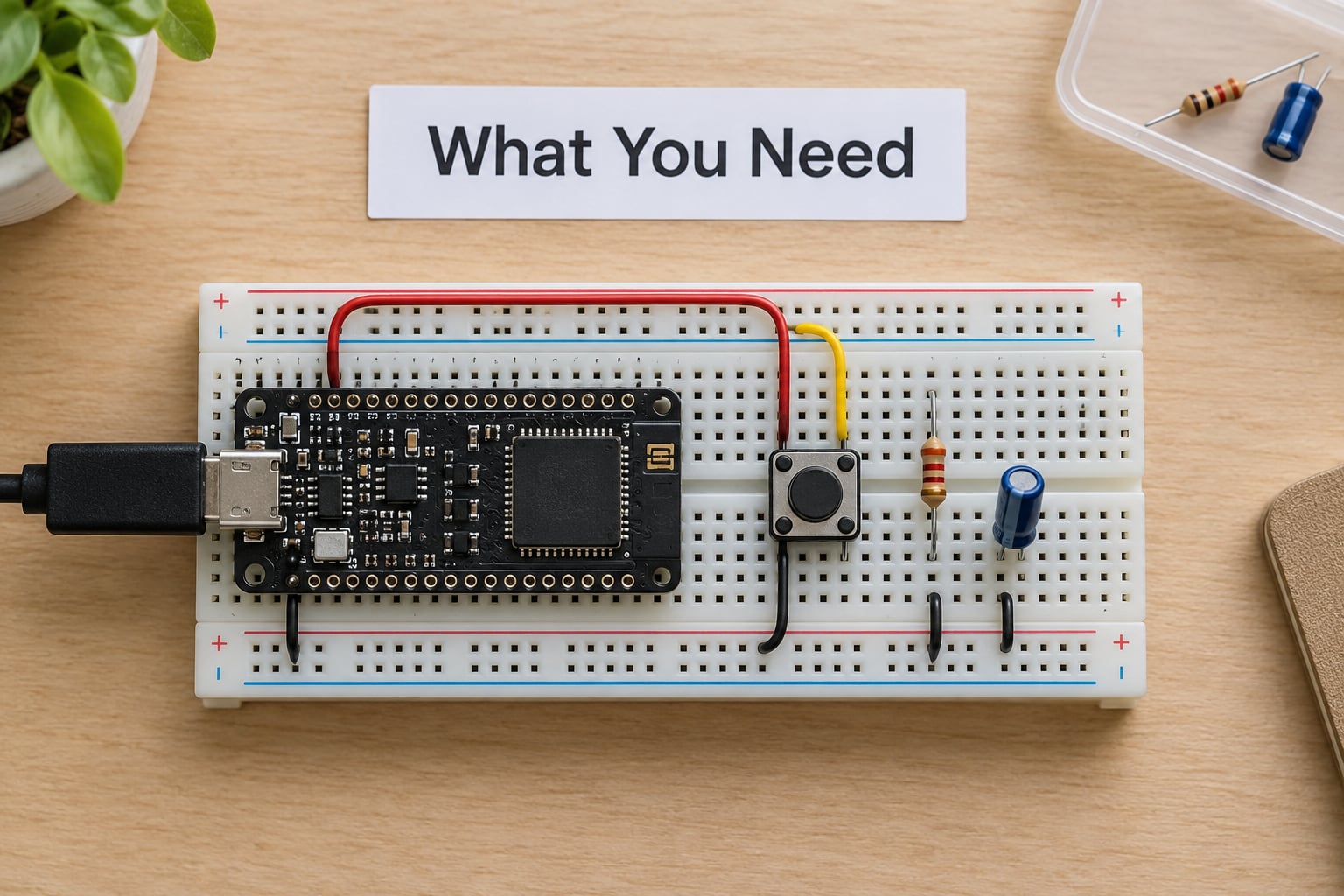
Any reliable debounce implementation starts with the same short parts list. You can build the whole thing with a switch, two passive components and the input stage your microcontroller already has.
- A mechanical switch. Tact, micro, toggle, rotary or a limit switch. Check the datasheet for the published bounce time at the operating load, since it varies with contact force, speed of actuation and current through the contacts.
- A pull-up or pull-down resistor. 10 kOhm is the usual choice for an MCU pin. This defines the resting logic level and stops a floating input from wandering when the switch is open.
- Capacitors for an RC filter. Common standard values between 10 nF and 1 uF. Pair them with a resistor in the same range to set the time constant.
- A Schmitt-trigger input. Most modern MCU GPIO pins are Schmitt-trigger inputs by default. Confirm it in the reference manual, because that single fact decides whether an RC filter alone can work.
- A microcontroller with a millisecond timer. Any part with a hardware timer gives you non-blocking timing. Software serial or delay-based loops make this much harder to do cleanly.
- A defined response-time requirement. Decide how much lag the application can tolerate before you pick a debounce interval. Machine controls and menu navigation have very different budgets.
If you already have a board such as an Arduino Uno or an STM32 Nucleo, the pull resistor is often already populated on the button header. That matters later, because double debouncing is a common failure.
Step-by-Step: How to Debounce a Switch in Hardware and Software
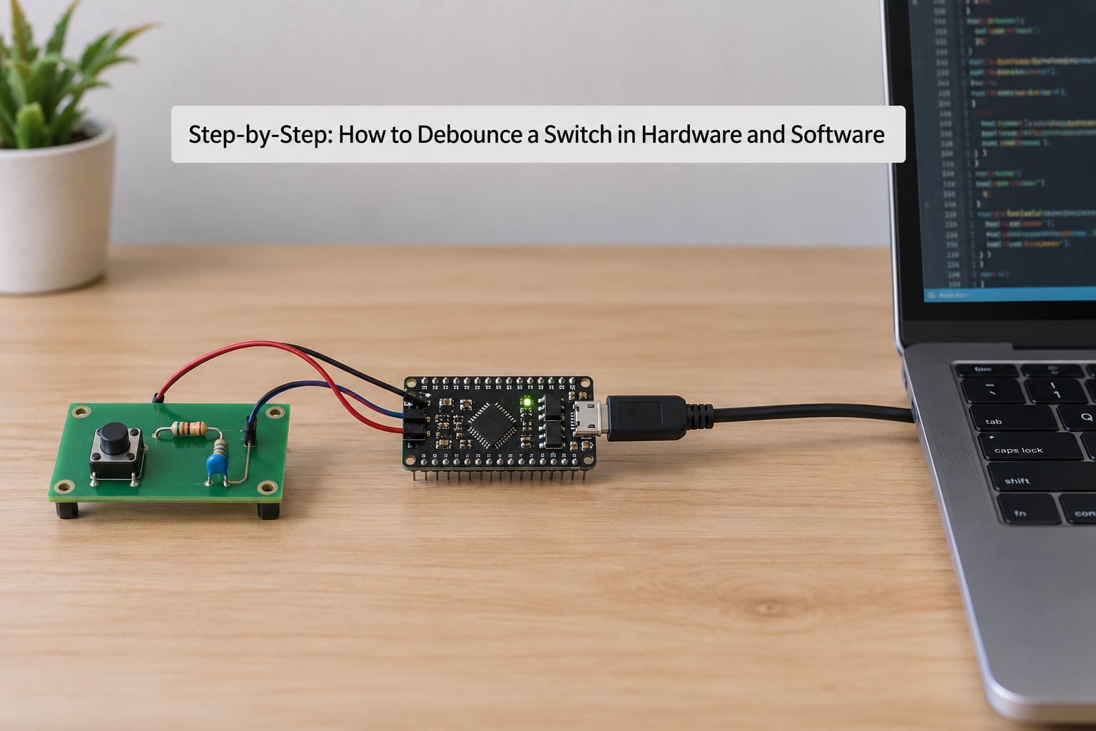
The order below is deliberate. Decide what you are debouncing first, add the hardware that suits the environment, then write firmware that matches the measured switch rather than a value copied from somewhere else.
How to Debounce a Switch in Hardware
A hardware debounce works by physically preventing the bounce pulses from reaching the logic threshold. Start with the pull resistor, then add filtering.
Wire the pull resistor from the pin to the supply rail for an active-low button, or to ground for an active-high input. With a 10 kOhm pull-up, an open switch reads a clean logic high and a closed switch reads a clean logic low.
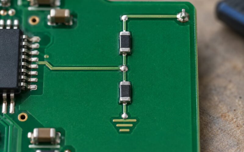
Then put a resistor in series with the switch and a capacitor from the input pin to ground, which forms an RC low-pass filter. The capacitor charges through the resistor, so the pin voltage moves along an exponential curve instead of jumping instantly. The time constant is tau = R x C, and the pin reaches roughly 63 percent of the final level after one tau.
Here is how the filter time constant scales with real component values:
| Series R | Capacitor C | Time constant | Rough settling at 5x tau |
|---|---|---|---|
| 1 kOhm | 1 uF | 1 ms | 5 ms |
| 10 kOhm | 1 uF | 10 ms | 50 ms |
| 10 kOhm | 100 nF | 1 ms | 5 ms |
| 100 kOhm | 100 nF | 10 ms | 50 ms |
| 47 kOhm | 470 nF | 22 ms | 110 ms |
The rule of thumb from component datasheets is to make five times the time constant longer than the published bounce time. A switch rated at 10 ms then wants a filter above 50 ms of settling, which is the point where you notice the lag.
Here is the part most guides get wrong. An RC filter alone is not a complete debounce circuit. The filtered edge is slow, and a slow edge crossing an ordinary logic threshold can still cross it more than once as the exponential curve interacts with noise and contact resistance. What fixes that is hysteresis, which is exactly what a Schmitt trigger provides: two different thresholds for rising and falling edges. The pin must travel past the higher threshold to register a high, and past the lower threshold to register a low, so small wiggles near the midpoint are ignored.
Most MCU pins already have that behaviour built in. If your input does not, a 74HC14 hex Schmitt-trigger inverter gives you six clean channels for a few cents and runs at the same supply voltage as the rest of the logic.
Dedicated debounce ICs such as the MAX6816, MAX6817 and MAX6818 family sit between those two options. They hold the first edge, filter for a fixed interval and then present a single clean pulse, with internal pull-ups on some variants. They cost several times more than a resistor and capacitor, so justify them when you have many switch inputs, a very fast response requirement, or a switch whose bounce is severe.
And do not forget the easiest hardware fix of all. A snap-action or positive-opening limit switch snaps the contacts closed in a single transition. Contact bounce nearly disappears, no filter is needed, and you keep full response speed.
How to Debounce a Switch in Software
Software debouncing accepts one change only after the input has been stable for the debounce interval. Do not use delay() for this: it stops your whole loop, which breaks serial handling, timers and every other input on the board. The r/arduino forum is full of threads with exactly that symptom.
This complete Arduino sketch never blocks. It reads the raw pin, timestamps any change, and only updates the stable state once the reading has held steady for DEBOUNCE_MS.
const byte BUTTON_PIN = 2;
const unsigned long DEBOUNCE_MS = 25;

bool lastRaw      = HIGH;      // most recent raw reading
unsigned long changedAt = 0;   // when that reading last changed
bool stableState  = HIGH;      // debounced state
bool lastEvent    = HIGH;      // last state we acted on
bool pressEvent   = false;     // set once per confirmed press

void setup() {
  pinMode(BUTTON_PIN, INPUT_PULLUP);
}

void loop() {
  bool raw = digitalRead(BUTTON_PIN);

  if (raw != lastRaw) {          // edge detected, restart the timer
    lastRaw = raw;
    changedAt = millis();
  }

  if (raw != stableState && (millis() - changedAt) >= DEBOUNCE_MS) {
    stableState = raw;           // stable long enough, accept it
    if (stableState != lastEvent) {
      lastEvent = stableState;
      pressEvent = (stableState == LOW);
    }
  }

  if (pressEvent) {              // act once per real press
    pressEvent = false;
    // increment counter, toggle relay, advance menu
  }
}
The unsigned subtraction in millis() - changedAt is deliberate. It stays correct when the timer wraps around, which it will eventually do on a 32-bit timer after roughly 49 days.
For an interrupt-driven design, keep the service routine as short as possible and do the timing there. This variant suits an STM32-class part where a falling-edge interrupt is enabled on the button pin:
volatile bool raw_flag = false;
volatile unsigned long edge_ms = 0;
volatile uint32_t stamp = 0;

void EXTI15_10_IRQHandler(void) {
  if (EXTI_Line & EXTI_Line13) {          // button pin
    EXTI->PR = EXTI_Line13;               // clear pending, write 1
    raw_flag  = true;
    edge_ms   = HAL_GetTick();
    stamp     = edge_ms;
  }
}

/* call from the main loop */
void button_service(void) {
  if (!raw_flag) return;
  raw_flag = false;
  if ((HAL_GetTick() - stamp) >= DEBOUNCE_MS &&
      HAL_GPIO_ReadPin(GPIOB, GPIO_PIN_13) == GPIO_PIN_RESET) {
    on_button_press();                       // one confirmed press
  }
}
Polling works fine for a handful of switches and is easier to reason about. Interrupts win when the loop has long blocking work or when a missed press is unacceptable, since a sleeping MCU still catches the edge.
Three more decisions shape the firmware. Triggering on the press edge gives the shortest response, while triggering on the release edge is quieter on worn switches because the release is usually cleaner. Asymmetric press and release intervals are fine and often sensible: a short press interval and a longer release interval makes rapid repeat presses more predictable. For scale, a switch matrix or 74HC165 shift register feeding several hundred switches costs the same per-switch logic but is scanned in slices rather than all at once.
Choose the Debounce Delay
The debounce interval must exceed the switch’s real bounce time, and any value below that guarantees missed presses. Start from the datasheet, then verify on your own hardware.
| Switch type | Typical bounce | Starting debounce interval |
|---|---|---|
| Snap-action / positive-opening limit switch | Under 1 ms | 2-5 ms or none |
| Micro miniature tact | 1-5 ms | 10 ms |
| Standard tact or panel pushbutton | 5-20 ms | 20-25 ms |
| Toggle or sealed industrial switch | 10-50 ms | 50 ms |
| Reed relay, old or worn contacts | Variable | 80-100 ms |
Latency is the cost. A 25 ms debounce means a 25 ms delay between the physical press and your code noticing it, which is below the threshold most people perceive on a button but is clearly visible on a fast machine control loop. If your application has a hard response budget, a snap-action switch plus a 5 ms filter beats a worn tact switch plus a 100 ms timer every time.
Debouncing is also not the only way to limit how often something happens, and mixing the three up causes confusion:
| Technique | What it does | Typical value |
|---|---|---|
| Debouncing | Ignores transitions until the signal is stable, turning one physical action into one event | 5-50 ms |
| Throttling | Processes events at most at a fixed rate, deliberately dropping the ones that arrive faster | 100 ms to seconds |
| Rate limiting | Caps how much action is allowed over a window, usually for cost, load or abuse reasons | 10-100 per second |
One safety note that overrides everything else in this section. Never apply a software debounce to an emergency stop, a guard interlock or any input on a safety-rated circuit. Those devices are designed to trip on the first transition, and adding a delay to a stop function is a serious hazard. Use a safety relay or a safety-rated input stage instead, and treat debouncing as a usability feature for operator panels only.
Test and Tune the Implementation
Verify debouncing on the bench rather than trusting a copied default. The procedure takes about ten minutes and catches most problems before they reach the field.
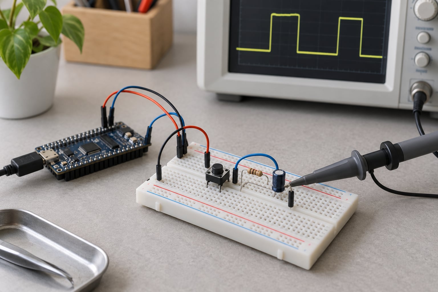
Measure the real bounce first. Connect a scope channel to the raw switch node, referenced to the same ground as the board, with the probe tip touching the contact or pad. Use a timebase around 5 ms per division for a tact switch and 20 ms per division for a noisier panel button. Actuate the switch the way a person would, about ten times.
Read the total width of the ringing cluster for each actuation and write down the worst case, not the average. Note the trigger level you used, because bounce changes with voltage and load. If the trace is flat and no ringing appears, the switch is snap-action and you may not need a filter at all.
Then check the filtered node the same way. With the RC filter in place, the trace should be a smooth exponential with no re-crossings. If you see multiple edges at the pin, your input is missing hysteresis and needs a Schmitt trigger.
Verify the firmware with a counted test. Actuate the switch 1000 times with a deliberate mix of slow presses, fast presses and taps, and confirm the counter advanced by exactly 1000. Repeat with the switch 30 centimetres away on a cable run, since that is where EMI coupling shows up.
Finally, power-cycle the board ten times with the button held down. On startup the pin floats for a moment, and without an explicit initialisation you can get one phantom event at boot.
Field failures usually come from noise rather than bounce. A VFD or a mains relay in the same enclosure injects spikes that no reasonable software interval will remove, and the fix is shielded cable, a proper ground reference, or an opto-isolated input module rather than a longer debounce.
Common Mistakes
Almost every stubborn double-trigger case falls into one of these patterns.
An RC filter with no Schmitt trigger. The slow edge re-crosses the logic threshold and you still get multiple transitions. Fix: confirm the pin is a Schmitt-trigger input in the reference manual, or add a 74HC14 stage.
A debounce interval below the real bounce time. More filtering makes it worse by cutting the tail off. Fix: measure the worst-case trace, then set the interval above it.
Using delay() for the debounce. The loop stops and unrelated timing breaks, which sends you chasing the wrong bug. Fix: use the millis() pattern above.
Missing or wrong pull resistor. An unterminated input drifts across the threshold on its own. Fix: 10 kOhm to the rail for active-low wiring, and check that the pin’s internal pull-up is actually enabled.
Noisy breadboard or long jumper wiring. Breadboard contacts add capacitance and pick up interference, and unshielded runs turn the node into an antenna. Fix: shorten the wiring, keep the RC close to the pin, or add an opto-isolator for runs beyond a couple of metres.
No initialisation at boot. The first read after reset can fire a phantom event. Fix: set the raw, stable and last-event variables from an immediate read of the pin before entering the main loop.
Increasing the interval to hide a worn switch. This is the most common wrong turn on the forums. A switch that bounces 300 ms is failing or contaminated, and no timer fixes it. Fix: replace the switch, or move to a Hall-effect or inductive proximity sensor where the application allows it.
Double debouncing. Many development boards already put an RC filter on the user button header. Adding a 5 ms firmware debounce on top of a 20 ms hardware filter gives an odd total delay and can leave the press still ringing. Fix: measure the board’s existing filter, then set the firmware interval clearly longer than it.
Unstable initial threshold on an opto-isolated input. Optocoupler outputs have slow, asymmetric edges and need more filtering than a plain CMOS input. Fix: add an RC on the opto side and give the firmware a longer interval.
Frequently Asked Questions
How can I debounce a switch using Arduino code?
Use a non-blocking timestamp approach instead of delay(). Read the pin in loop(), and whenever the raw reading differs from the previous one, record the change with millis(). Only update the stable state once the reading has held the same value for your debounce interval, typically 20-25 ms. Act on the confirmed state once, so a single press produces a single event. Use INPUT_PULLUP with a button that connects the pin to ground.
What is a switch debouncer?
A switch debouncer is the filter that turns the burst of rapid transitions a mechanical contact produces into one clean state change. When two contacts meet, the springy leaves rebound against each other for a few milliseconds and the input pin sees several edges. A debouncer, whether built from an RC filter and Schmitt trigger in hardware or from a timer in firmware, accepts the change only after the signal is genuinely steady.
What is the best debounce time?
For a standard tact or panel pushbutton, 20-25 ms is the best starting point, and most designs work in the 10-50 ms range. Snap-action limit switches need only 2-5 ms or nothing at all, while toggle switches and worn contacts can need 50-100 ms. Start from the switch datasheet, then measure your own hardware with a scope and set the interval above the worst bounce you observe.
What is debouncing vs. throttling?
Debouncing removes spurious edges caused by contact bounce so that one physical action becomes one event. Throttling processes events at a limited rate and deliberately discards anything that arrives faster than that limit. Debouncing protects you from hardware noise, while throttling protects you from software or user behaviour such as holding a button down. They solve different problems and are often used together on the same input.
Is an RC filter alone enough to debounce a switch?
Not on its own. An RC low-pass filter slows the edge, but that slow edge can still cross an ordinary logic threshold more than once, so bounce survives in a different form. Add hysteresis with a Schmitt trigger, whether that is built into the microcontroller pin or provided by a 74HC14, and the repeated crossings disappear. If your input has no Schmitt-trigger stage, an RC filter alone will not be reliable.
Conclusion
Start here: fit a 10 kOhm pull resistor, check whether your MCU pin is a Schmitt-trigger input, then pick a debounce interval above the switch’s published bounce time. Twenty milliseconds is a sane starting point for a panel pushbutton, and five is plenty for a snap-action limit switch.
Add an RC filter when the wiring is long or the environment is noisy, and add firmware debouncing whenever the response time matters. Most designs end up with both, with the firmware interval set clearly longer than any hardware filter already on the board.
Then measure. Ten minutes with a scope and a 1000-press count tells you more than any default value copied from a forum thread, and it is the difference between a button that works and one that costs you a weekend.