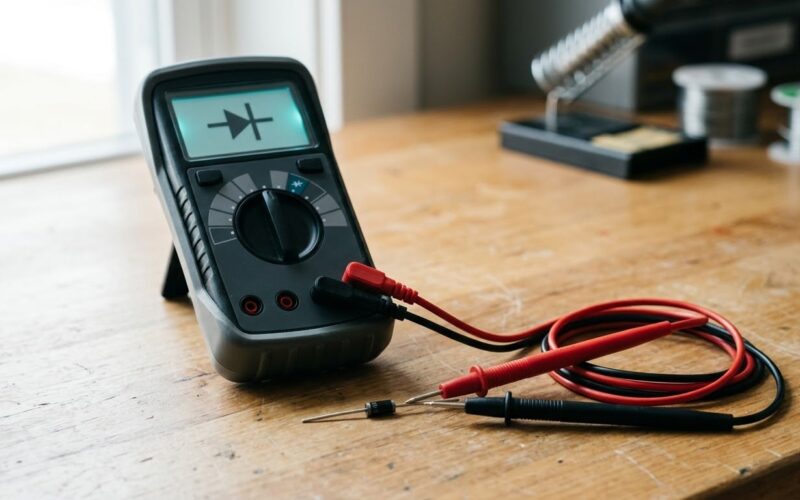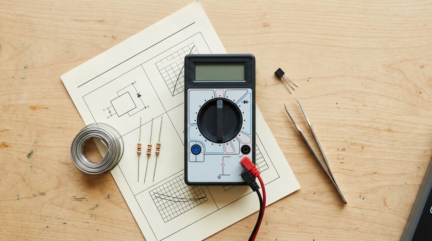
To test a transistor with a multimeter, set the dial to diode mode, take the part out of the circuit if you can, then measure from the base to the emitter and from the base to the collector. A healthy bipolar transistor reads roughly 0.55 to 0.75 V with the base forward biased, OL (over range) with the base reversed, and no continuity between collector and emitter.
The whole job takes about five minutes. What it cannot do is tell you the transistor has gain, so technicians call it a DORA test: dead or alive, nothing more. Read on for the readings, and for the point where a meter stops being enough.
Table of Contents
- What You Need
- Step-by-Step: How to Test a Transistor with a Multimeter
- Step 1: Remove power and desolder the transistor
- Step 2: Set the dial to diode mode
- Step 3: Take all six readings and find the base
- Step 4: Judge the base junctions for an NPN transistor
- Step 5: Judge the base junctions for a PNP transistor
- Step 6: Check collector to emitter for a short
- What the readings mean: good NPN, good PNP, shorted and open
- Expected forward voltage by transistor type
- Worked example: a BC547 and a C1815
- In-circuit vs desoldered: what you can trust
- Beyond the multimeter: hFE, component testers and curve tracers
- Common Mistakes
- Frequently Asked Questions
- What should a good transistor read on a multimeter?
- How do I know whether a transistor is NPN or PNP?
- Why does my transistor test differently while it is still on the circuit board?
- What does a zero reading between the collector and emitter mean?
- Can I test a transistor using only resistance mode?
- When should I replace a transistor instead of testing it again?
- Conclusion
What You Need
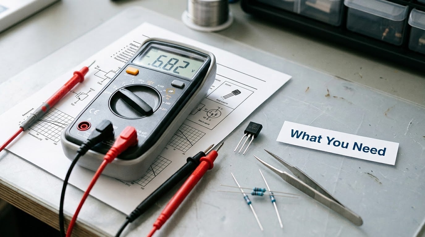
- A digital multimeter with a diode-test function. Diode mode is the only setting that gives you a repeatable voltage drop. Any modern handheld has it; a cheap one without it is nearly useless for this job.
- Tweezers or fine spring-loaded probes. You need to hold three contacts at once without bridging two of them.
- A soldering iron, solder wick and flux for lifting the transistor out, if the board is not single-sided.
- The datasheet or part number. Pin order is not universal and the base is often not the middle lead.
- A known-good transistor of the same type. Having a healthy BC547 on the bench turns guesswork into a comparison.
- An ESD mat and wrist strap if you will be probing MOSFETs or IGBTs, which can be destroyed by the static from your hands.
Work on a bench, not on equipment connected to mains. A transistor test needs no external power at all, so if the device you are probing is energised, stop and discharge it first.
If you want a broader view of how parts get verified once they leave the bench, Automated Test Equipment Basics for Beginners covers the same idea at production scale.
Step-by-Step: How to Test a Transistor with a Multimeter
Step 1: Remove power and desolder the transistor
Unplug the supply and confirm with the meter in voltage mode that no rail is live. Then desolder the transistor, noting which pin went where before it comes off, because the two outer pins are easy to swap on the way back in.
Desoldering is what makes the reading trustworthy. On the board, other parts sit across the junctions and the result is often meaningless.
Step 2: Set the dial to diode mode
Turn the dial to the diode symbol, the triangle pointing at a line. On a digital meter this applies a small test current, usually between 1 and 3 mA, and displays the resulting forward voltage as a number with a V after it. A reading of 0.00 to 0.80 is a real voltage drop; anything above the range shows as OL, 1 or open.
Do not use the resistance range for junction testing. An ohms figure depends on the test current, which changes with the range and the meter, so a reading of a few hundred ohms tells you nothing on its own. That convention still floats around in older textbooks and it causes more confusion than anything else on this subject.
Step 3: Take all six readings and find the base
Three leads give three pairs, two probe polarities each: six readings. Write them down in a grid.
- Red on lead A, black on lead B
- Red on lead B, black on lead A
- Red on lead B, black on lead C
- Red on lead C, black on lead B
- Red on lead A, black on lead C
- Red on lead C, black on lead A
A working transistor conducts in exactly two of those six, and both of them involve the same lead. That shared lead is the base. Four readings showing OL and two showing a diode drop is the signature of a healthy junction pair.
Once you know the base, the type follows from polarity. If red on base and black on another lead gives a drop, it is NPN. If black on base and red on another lead gives a drop, it is PNP.
Step 4: Judge the base junctions for an NPN transistor
Red probe on the base, black probe on the emitter: expect 0.55 to 0.75 V. Now black on the base, red on the emitter: expect OL. That single flip distinguishes a working base-emitter junction from an open one.
Repeat with the collector. Red on base and black on collector gives a similar drop, often a touch higher than the emitter reading because the collector junction is more lightly doped. Reverse the probes and you should see OL again.
Step 5: Judge the base junctions for a PNP transistor
Everything inverts. Black probe on the base, red on the emitter should read 0.55 to 0.75 V. Flip to red on base, black on emitter and the meter should show OL. The collector pair behaves the same way.
If your readings match the NPN pattern while you expected PNP, you have almost certainly swapped the probe colours rather than found a fault.
Step 6: Check collector to emitter for a short
With the base left floating, touch the probes across collector and emitter in both directions. A healthy transistor reads OL both ways. Anything near 0.00 V, or a continuity beep in either direction, means the device has failed short and the junction readings no longer matter: it is scrap.
What the readings mean: good NPN, good PNP, shorted and open
Here is the whole decision in one place. For an NPN, red goes on the base; for a PNP, black does.
- Good NPN: base to emitter 0.55 to 0.75 V, base to collector 0.55 to 0.75 V, both base-reversed combinations OL, collector to emitter OL in both directions.
- Good PNP: the same six readings with the probe polarity reversed.
- Shorted transistor: collector to emitter near 0.00 V or continuity in either direction, or a base junction reading around 0.00 V in both directions. Both come from the same failure, thermal or avalanche damage to the junctions.
- Open transistor: both base junctions show OL in both directions, and collector to emitter is infinite. An internal break or a lifted pin does this.
- Marginal transistor: a forward drop far below the expected value, or a reading that drifts when you press on the case or warm the part with your fingers. Replace it.
Two of six combinations conducting is the pass rule. Zero, one, three or more means something is wrong.
Expected forward voltage by transistor type
The 0.55 to 0.75 V band is for ordinary silicon. Different constructions land in different places, and knowing the expected number stops you condemning a healthy part.
- Silicon BJT (BC547, 2N3904, C1815, TIP31): 0.55 to 0.75 V at both base junctions.
- Germanium (AC127, OC44 and similar): 0.15 to 0.30 V. A germanium part that reads 0.65 V is not germanium.
- Darlington (TIP120, ULN2803): 1.1 to 1.4 V at the base junction, because two junctions and two drops are in series.
- Complementary output pairs in audio amplifiers: when both bases are tied together, each transistor’s drop still reads 0.55 to 0.75 V on its own. If you probe across the pair’s outer terminals you will see the two drops added, so lift the shared base connection before judging them.
- Schottky-clamped power stages: the clamp adds a junction, so readings can sit lower than plain silicon values suggest. Check the schematic before assuming a fault.
Worked example: a BC547 and a C1815
The BC547 is the small-signal NPN everyone reaches for, and the C1815 is its near-equivalent from other manufacturers. Both are silicon, so both should read 0.55 to 0.75 V forward and OL reverse.
Say you take a BC547 out of an amplifier and get 0.62 V from base to emitter, 0.68 V from base to collector, OL on both reversed base readings, and OL across collector to emitter. That is a healthy part: it still switches and it still passes voltage, though its gain is unknown.
Now a C1815 from the same board reads 0.64 V and 0.69 V on the base pairs but only 0.05 V from collector to emitter. That collector-emitter short is the failure, and it explains a channel that distorts instead of cleanly clipping. Swap the transistor and the channel comes back.
If both parts read OL in every direction, suspect your meter setting before the parts. A lead that has come loose, or a dial left on continuity, will do that.
In-circuit vs desoldered: what you can trust
You can test a transistor on the board, but only as a screening step. Four things routinely distort an in-circuit reading.
- Base-emitter shunt resistors. Many driver stages put tens of ohms directly across the base-emitter junction, which drags the reading down and can look like a short.
- Protection diodes. Diodes from base to case, common in audio output pairs, conduct in parallel with the junction and mask a leak.
- TVS or zener clamps across the junctions add a third, unexpected junction to your six-reading grid.
- Supply paths. Through neighbouring parts, the collector and emitter can see a supply rail, so collector-emitter reads a diode drop instead of OL.
The rule: trust an in-circuit result only when it matches what a loose device should read. Anything worse is inconclusive, not a verdict. Lift the base pin first, since it is the easiest to free and it isolates both junctions at once.
Beyond the multimeter: hFE, component testers and curve tracers
Many meters have a round transistor socket marked hFE. Insert the part, read a number, done. That number is the DC current gain at one fixed bias current, and it is a useful sanity check: a small-signal transistor landing between roughly 100 and 800 is unremarkable. A figure near zero is a red flag no junction test will catch.
A dedicated component tester goes further and prints the device type, pinout and gain in one press. For MOSFETs, expect OL from the gate to either other lead in both directions, and low resistance from drain to source in both directions with the body diode showing as a one-way drop.
For actual characterisation, leakage under bias, or a device that passes every junction test and still misbehaves, the answer is a curve tracer, not a better multimeter.
Common Mistakes
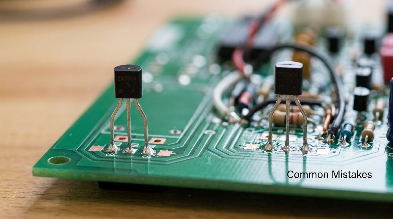
Most failed transistor checks trace back to one of eight mistakes, and each has a straightforward fix.
Testing with the board powered. Test current fights the circuit and can bend the readings anywhere. Unplug, discharge, then probe. Fix: confirm zero volts across the supply terminals in voltage mode before touching anything.
Using the resistance range. An ohms figure moves with the meter, the range and the test current, so 500 to 1500 ohms is not a pass criterion for anything. Fix: diode mode, always.
Assuming the base is the middle lead. It very often is not, and datasheets disagree about lead order between packages. Fix: identify the base from the six readings, not from the drawing in your head.
Reversed probe polarity. A healthy PNP shows OL where you expected a drop, and a healthy NPN does the same in reverse. Fix: if exactly two of six combinations conduct, the type is whatever polarity conducts, not whatever the part bag says.
Treating OL as proof the part is good. OL is the expected reverse reading, so a healthy device shows it four times out of six. Fix: judge the pattern of all six readings together, never one reading alone.
Forcing power into the device during the test. Driving current or voltage through a junction to see if it reacts risks destroying a part that was fine. Fix: the meter supplies its own small test current; nothing else is needed.
Assuming every three-lead part shares one lead order. MOSFETs, JFETs, SCRs and voltage regulators all differ. Fix: check the datasheet for the family, and treat gate-insulated devices on their own terms.
Reading a passing test or a high hFE figure as proof of health. A junction test proves the junctions are not dead. It says nothing about gain, leakage at voltage, or thermal behaviour. Fix: treat the diode test as a screen, then power the circuit and confirm the fault is gone.
Frequently Asked Questions
What should a good transistor read on a multimeter?
In diode mode, a healthy transistor shows two readings of about 0.55 to 0.75 V, both involving the base lead, and OL in the other four combinations. With the base left floating, collector to emitter should read OL in both directions. Exactly two of the six readings conduct. Anything near 0.00 V across collector and emitter means a short, and OL everywhere means an open junction.
How do I know whether a transistor is NPN or PNP?
Take all six probe combinations and find the one lead that appears in both readings that conduct: that is the base. If red probe on base with black on another lead gives the drop, the part is NPN. If black on base gives the drop, it is PNP. Germanium and Darlington parts work the same way but at different voltages.
Why does my transistor test differently while it is still on the circuit board?
Other components sit across the junctions you are trying to measure. Base-emitter shunt resistors, protection diodes, zener clamps and paths through the supply rail all add current that the meter sees but the junction does not. An in-circuit result is worth trusting only when it matches what a loose device should read. Lift the base pin first, or desolder the transistor.
What does a zero reading between the collector and emitter mean?
It means the transistor is shorted and has failed. A healthy device blocks current between collector and emitter in both directions and reads OL. Zero volts or a continuity beep in either direction indicates the junctions have broken down, usually from overheating or a voltage spike. Such a part will not recover and should be replaced.
Can I test a transistor using only resistance mode?
You can get a rough idea, but you should not trust it. The ohms reading depends on the meter internal battery, the test current and the range selected, so two different meters can disagree on a healthy part. Diode mode gives a repeatable forward voltage instead, which is why it replaced the old resistance-range convention on virtually every modern meter.
When should I replace a transistor instead of testing it again?
Replace it when the junction readings show a short or an open, when a forward drop sits far outside the expected range for the device type, or when the reading drifts as you press on the case. Also replace a part that passes every junction test but whose symptom never disappears, since gain, leakage and thermal faults will not show up on a multimeter at all.
Conclusion
If you remember one procedure, remember this: isolate the transistor, identify which lead is the base, then measure base-to-emitter and base-to-collector in diode mode. Two drops around 0.55 to 0.75 V and no collector-emitter continuity means it is alive.
That is how to test a transistor with a multimeter well enough to decide whether to replace it. It will not measure gain, leakage under bias or anything about a high-power, high-frequency or specialist device, so confirm the fault is really gone with the circuit powered before you put the cover back on.