Learning how to simulate a circuit before building it means you draw the schematic, attach a model to every part, and run the whole thing through a SPICE engine that solves the circuit’s equations and plots voltage, current and power at every node. Do that before ordering boards or heating a soldering iron, and bad bias points, unstable loops and tolerance failures show up in minutes instead of over a board spin and a lost weekend.
Most of that value comes from discipline, not from the simulator. A schematic with generic symbols and ideal inductors will tell you beautifully wrong things, and the difference between a useful run and a wasted afternoon is whether you checked the models, the sources and the analysis type before you pressed Run.
Table of Contents
- What You Need
- A written goal for the circuit
- A schematic other people can read
- Datasheets, not memory
- Verified models for the parts you will actually buy
- A simulator
- Realistic operating constraints
- Step-by-Step: How to Simulate a Circuit Before Building It
- 1. Define what the circuit must do, in numbers
- 2. Capture the schematic before you draw the simulation
- 3. Attach a real model to every active part
- 4. Set sources, probes and ground correctly
- 5. Run DC operating point before anything else
- 6. Run transient analysis for behaviour over time
- 7. Run AC analysis for gain and stability
- 8. Stress the design with worst-case and Monte Carlo runs
- 9. Review, netlist, and plan the hardware test
- Common Mistakes
- Floating nodes and missing grounds
- Wrong or unpowered amplifier pins
- Typographical errors in values and units
- Ideal inductors and ideal capacitors
- Unrealistic source and supply models
- Timesteps that are too coarse
- Treating a nominal run as a guarantee
- Ignoring convergence errors
- Frequently Asked Questions
- Is circuit simulation necessary if I am only building a simple prototype?
- What type of simulation should I run first on a new circuit?
- Can I simulate a circuit with an integrated circuit that has no SPICE model?
- How accurate does a circuit simulation need to be before building?
- What is the difference between nominal, worst-case, and Monte Carlo simulation?
- Does a passing simulation mean I can skip testing the first prototype?
- Conclusion: Start With a Verified Schematic
What You Need
You need six things ready before the first run, and five of them are documents rather than software.
A written goal for the circuit
One sentence saying what the circuit must do, with numbers attached: input range, output range, load, accuracy, ambient temperature, and which supply rails it runs from. Without those numbers you cannot tell a passing simulation from a failing one, because a pass condition you have not written down does not exist.
A schematic other people can read
Use net names instead of numbers wherever you can, keep a single ground symbol per sheet, label the power rails clearly, and keep unrelated blocks on separate sheets. A schematic you cannot audit in five minutes will hide the same error the simulation was supposed to catch.
Datasheets, not memory
Pull the recommended operating conditions, absolute maximum ratings, pinout and typical performance curves for every active part. Model pinouts get copied from datasheets that were superseded, and a swapped pin is the cheapest error to make and the most expensive one to debug on hardware.
Verified models for the parts you will actually buy
A vendor SPICE model beats a generic symbol every time. Download the model for the exact part number from the manufacturer and read its header comment to confirm the pin order and the conditions it was characterised under. Where no model exists, build a subcircuit from the datasheet typicals and note in the file that it is a behavioural approximation.
A simulator
Free and capable options include LTspice, ngspice through KiCad, QSPICE and TINA-TI. Commercial platforms such as PSpice and OrCAD, SIMetrix with SIMPLIS, and Simulink with Simscape exist for licensed teams that need integrated schematic, layout and verification flows. Any of them runs the same underlying analyses; they differ in library depth, model import behaviour and how much setup they hide from you.
Realistic operating constraints
Supply rail tolerances, source impedance, output impedance, temperature range and component tolerances all belong in the setup before the first run rather than discovered during it. Write them as numbers next to the schematic.
Step-by-Step: How to Simulate a Circuit Before Building It
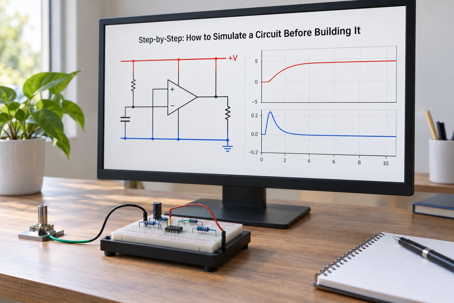
The workflow below runs in the order that catches the most expensive problems earliest. Each step states what output tells you the step actually worked.
1. Define what the circuit must do, in numbers
Write the input range, the output range, the load it will drive, the accuracy you need and the temperature range it must survive. This is also the document you will check the finished hardware against, so it earns its place twice.
2. Capture the schematic before you draw the simulation
Capture it in a schematic editor that can export a netlist, and let the tool generate the netlist rather than writing it by hand. Hand-written netlists are fine for a five-resistor divider and miserable for anything with feedback.
3. Attach a real model to every active part
Import the manufacturer model, map its pin order onto your symbol, and confirm the mapping by running a DC operating point and confirming the pin voltages match what the datasheet says they should be at that bias. A model wired to the wrong pins will still produce a waveform, which is exactly why it is dangerous.
4. Set sources, probes and ground correctly
Give every supply a real source with its intended source impedance, put a probe on every node you care about, and use one ground symbol per circuit. An ideal zero-ohm supply hides supply-inductance problems that then appear as ringing on the real board.
5. Run DC operating point before anything else
The DC operating point check succeeded when you can read a sensible bias state for every stage: divider ratios where the math says they should be, op-amp output voltages away from the rails, regulator pass devices with headroom across them. This single analysis catches most wrong-pin and mis-wiring errors.
6. Run transient analysis for behaviour over time
Transient analysis tells you whether the circuit works when the input changes. Confirm the output settles at the value you designed for and that nothing rings or saturates unexpectedly. If a stage is going to be switching, set the maximum timestep small enough to resolve the edges, or your ripple number is fiction.
7. Run AC analysis for gain and stability
AC analysis operates on the small-signal model around the DC operating point, so run it after the bias is right. Use it to read passband, gain, phase and phase margin on a feedback loop. A loop with negative phase margin oscillates on hardware no matter how clean the transient looked at startup.
8. Stress the design with worst-case and Monte Carlo runs
Once nominal results match your hand calculations, sweep the things you cannot control. Run the tolerances that matter most to output accuracy, then run a Monte Carlo pass with several hundred iterations. This is where you learn that a divider with 1 percent resistors lands outside your accuracy window for a small fraction of assemblies, which is a fixable design change and an expensive one to find after assembly.
9. Review, netlist, and plan the hardware test
Write down what the simulation cannot answer: thermal rise, EMI, mechanical fit, connector wear, and anything about the layout that changes current paths. Run an electrical rules check on the schematic, export the netlist for layout, and turn each pass condition from step one into a measurement you plan to make on the first board. Learning how to simulate a circuit before building it only pays off if the last step is written down while the simulation is still in front of you.
Common Mistakes
These are the errors that turn a simulation session into a lost afternoon. Each one has a correction you can apply immediately and a habit that prevents it.
Floating nodes and missing grounds
A node with no DC path to ground has no defined voltage, and the solver either reports a singular matrix or invents one. Add a high-value resistor from each suspicious node to ground, and as a review rule, look for any node whose only connection is through a capacitor at DC.
Wrong or unpowered amplifier pins
Leaving a supply pin floating, or wiring the supply to the wrong pin on a generic symbol, produces a plausible-looking output that is meaningless. Review habit: cross-check the symbol pinout against the datasheet drawing every time you import a new amplifier, and confirm supply pins sit at the rail voltages in the DC operating point.
Typographical errors in values and units
The classic offender is writing 10u where you meant 10 microfarads and getting 10 farads, or typing a resistor value with the wrong prefix. Review habit: recompute two or three values by hand before you trust the plot.
Ideal inductors and ideal capacitors
Ideal inductors have no winding resistance, no saturation and no core loss, and ideal capacitors sit right next to the pins with no loop inductance. Add series resistance and, where it matters, a parallel resistance and a saturation limit. This is the difference between a converter that simulates at 90 percent and one that oscillates on the bench.
Unrealistic source and supply models
An ideal voltage source cannot sag, and a model that ignores supply decoupling will hide supply noise problems. Model the source with the output impedance of the real supply or bench instrument, and include the bypass capacitors from your schematic rather than the datasheet ideal.
Timesteps that are too coarse
If your maximum timestep is larger than the switching period, the solver skips the peaks entirely. Set a maximum timestep and re-run; if the ripple figure changes significantly, your earlier number was an artefact of the solver.
Treating a nominal run as a guarantee
A nominal simulation tells you the design works with every part at its typical value and the temperature you typed in. It says nothing about tolerance spread, aging, ambient extremes or layout-induced effects. The habit that keeps you honest: state the run conditions above every plot, and never quote a result without them.
Ignoring convergence errors
Convergence failure means the solver could not find a consistent solution, which usually points at a modelling problem rather than a solver problem. Work through it in this order: add a small series resistance to every inductor and to any ideal source, check for conflicting sources driving one node, confirm no floating nodes, set a smaller maximum timestep, add initial conditions with UIC for switching circuits, and try gmin stepping or a source stepping option in the solver. If it still fails at DC, the problem is almost always topology or a model pin mapping.
Frequently Asked Questions
Is circuit simulation necessary if I am only building a simple prototype?
For a divider, a single LED circuit or a direct battery-to-motor hookup, the time is better spent on a quick bench check. Simulation starts earning its keep once the circuit has feedback, multiple stages, a part with a wide tolerance, or a supply that can be disturbed. The rule I use is simple: if a wrong answer would cost a board spin or a debugging weekend, simulate it first.
What type of simulation should I run first on a new circuit?
Run the DC operating point analysis first, every time. It is the fastest check and it catches the most common errors: mis-wired pins, wrong divider ratios, saturated amplifiers and regulators without headroom. AC and transient analyses both build on that bias state, so a wrong operating point quietly contaminates everything you run afterwards.
Can I simulate a circuit with an integrated circuit that has no SPICE model?
Yes. Most vendors publish models for their larger parts, so search the manufacturer site and the distributor pages first. If none exists, build a subcircuit from the datasheet typicals: input bias current, output impedance, gain bandwidth, slew rate and saturation limits usually reproduce the behaviour you care about. Label it as a behavioural model in the file and treat its numbers as estimates.
How accurate does a circuit simulation need to be before building?
Accurate enough to distinguish between two design options, and accurate enough that your worst-case predictions match reality. You do not need four significant figures, because the model error usually exceeds that. The useful discipline is checking against a known bench measurement after the first build, then tightening the model where it disagreed.
What is the difference between nominal, worst-case, and Monte Carlo simulation?
A nominal run uses every part at its typical value, which tells you how the design behaves at its centre. A worst-case run moves each part to a corner and gives you the guaranteed limit. A Monte Carlo run samples many random combinations to show the distribution, which tells you what fraction of assemblies land outside your specification. Nominal alone is the one that surprises people.
Does a passing simulation mean I can skip testing the first prototype?
No. Simulation verifies the design against your models; bench measurement verifies the simulation. You still need to measure the pass conditions you defined, plus the things no solver predicts: temperature rise, radiated and conducted emissions, mechanical fit, connector reliability and layout effects on current paths. Prototype testing confirms the model, not the design.
Conclusion: Start With a Verified Schematic
Start with the part most people skip: write down what the circuit must do, then verify the schematic and the models before you trust any result. Run the DC operating point to confirm bias, transient analysis to confirm behaviour, AC analysis for loop stability, and a tolerance sweep before parts are ordered.
Simulation is a design-confidence tool, not a guarantee of real-world performance. It tells you the design works against the models you supplied. Bench measurement tells you whether the models were right, and that is a question no solver can answer for you.