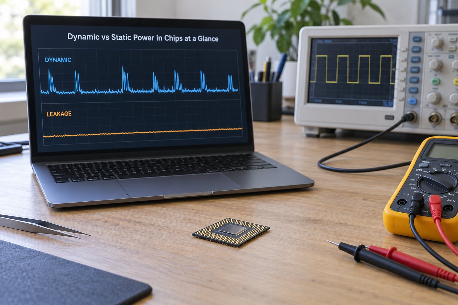
Dynamic power is the power a chip burns while its nodes are switching, charging and discharging load capacitance. Static power, also called leakage power, is the power drawn continuously while the circuit is powered but idle. Total chip power is the sum of the two: P_total = P_dynamic + P_leakage.
That is the whole split, and it decides everything else in low-power design. Dynamic power only flows when something toggles, so gating the clock or dropping the supply voltage collapses it. Leakage keeps flowing the entire time the rail is up, so only removing power from a block, raising threshold voltage, or cooling it moves the number.
Understanding dynamic vs static power in chips matters because the two respond to completely different levers. Attack one and the other does not budge, which is why a design can pass every activity check and still burn watts on a phone sitting in a pocket. Below is the breakdown, with formulas, a worked number, and the technique that belongs to each side.
Table of Contents
- Dynamic vs Static Power in Chips at a Glance
- What Is Static Power in Chips?
- The main leakage mechanisms
- How static power is calculated
- What Is Dynamic Power in Chips?
- The three components of dynamic power dissipation
- The formula and what each term means
- A worked numeric example
- How Static and Dynamic Power Differ
- Voltage and frequency behave differently
- Why the balance shifted at advanced nodes
- How EDA tools name the two components
- Why a power report can show dynamic power as zero
- Which Type of Power Usually Matters Most?
- Where leakage dominates
- Where dynamic power dominates
- How to Reduce Static Power
- Common misconception: clock gating does not remove leakage
- How to Reduce Dynamic Power
- Energy versus power: why frequency alone is not enough
- Static Power vs Dynamic Power: Which Should You Choose?
- Frequently Asked Questions
- What is the difference between dynamic and static power?
- What is meant by static power?
- How is static power calculated?
- How to reduce dynamic power dissipation in VLSI?
- Why does clock gating not reduce static power?
- Conclusion
Dynamic vs Static Power in Chips at a Glance
| Property | Dynamic power | Static power |
|---|---|---|
| Physical cause | Charging and discharging node capacitance, short-circuit current during transition, glitch toggles | Current through transistors that are nominally off, plus gate oxide and junction paths |
| Formula | P_dynamic = alpha × C_eff × V^2 × f | P_leakage = V × I_leak |
| Depends on activity | Strongly. Scales with the activity factor alpha | Not at all. Constant while the rail is up |
| Strongest dependency | Supply voltage, squared | Temperature and threshold voltage |
| When the block is idle | Near zero if the clock is gated | Still flowing at full rate |
| Process sensitivity | Improved slowly with node scaling | Rises sharply as Vt is lowered for performance |
| Main levers | Clock gating, operand isolation, MSV, DVFS, smaller capacitance | Multi-Vt cells, body bias, power gating and PSO, sizing |
| How it shows up in reports | Dynamic or switching power line | Device static and design-dependent static lines |
| Dominant in | Active processors, GPUs, AI accelerators | Always-on islands, analog and RF blocks, long standby |
One row deserves emphasis. Dynamic power falls with the square of voltage, which is why a modest voltage drop is the single biggest lever available. Static power has no activity term at all, so no amount of clever RTL will remove it while the supply stays connected.
What Is Static Power in Chips?
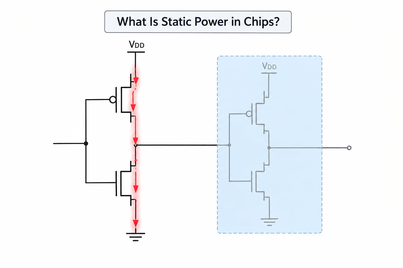
Static power is the power a CMOS circuit consumes while it is doing nothing. In an ideal complementary CMOS gate, one transistor is always on and the other always off, so the direct path from supply to ground is blocked and the steady-state current is zero. Real transistors are not ideal switches, and that nonzero current is the leakage that shows up as static power.
The main leakage mechanisms
Four mechanisms account for nearly all of it in a modern process node:
- Subthreshold leakage — the dominant term. A transistor that is meant to be off still conducts a small current when its gate voltage sits above the threshold voltage. This is why the term “off” is really “barely on.”
- Gate oxide tunneling — current tunnelling through the thin gate dielectric. The oxide thinned as nodes advanced, so this term grew substantially during the 3 nm era.
- Junction leakage — reverse-biased source and drain junctions leaking into the substrate or well.
- Substrate and well current — leakage injected through the body, including the band-to-band component at high fields.
How static power is calculated
The calculation is simple: P_leakage = V × I_leak. Multiply the supply voltage by the total leakage current of the block and you have its static power. The hard part is I_leak itself, because it depends on three variables you do not control at RTL.
- Threshold voltage (Vt). Leakage rises exponentially as Vt drops. Designers lower Vt to gain speed, which is precisely why leakage became a problem.
- Temperature. Leakage roughly doubles for every 10 degree Celsius rise over the normal operating range. A chip that fits its power budget at 25 degrees can miss it at 105 degrees.
- Process corner. Leakage varies widely between the slow, typical, and fast corners. Teams sign off at the slow-corner high-temperature case precisely because leakage is highest there.
So static power is not one number. It is a family of numbers that depends on corner, temperature, and what state the logic is holding, which is why power reports quote it at a specific operating point.
What Is Dynamic Power in Chips?
Dynamic power is everything the circuit burns while nodes move. It is the dominant term in any block that is actually computing, and it is the reason a modern accelerator draws hundreds of watts while running a neural network but a fraction of that while idle.
The three components of dynamic power dissipation
- Capacitive switching. Charging a node from 0 to V takes half a C×V^2 of energy from the supply, and dumping it during discharge returns only half back to the rail. The other half is burned in the driver. This term is essentially all of dynamic power in a well-designed block.
- Short-circuit current. During a transition both the pull-up and pull-down transistor conduct briefly while the input sits between the rails. The charge drawn during that overlap window is short-circuit power, and it scales with the transition time t_sc and the supply voltage.
- Glitch power. Hazards in combinational logic toggle nodes without changing the logical output. Every one of those toggles charges real capacitance and costs real energy, and it grows with logic depth and fanout.
The formula and what each term means
P_dynamic = alpha × C_eff × V^2 × f, where alpha is the activity factor (the average fraction of nodes switching per cycle), C_eff is the effective switched capacitance, V is the supply voltage, and f is the clock frequency.
The V^2 term is why voltage scaling has always been the most effective dynamic power technique. Cut voltage by 20 percent and dynamic power drops by about 36 percent. Halve frequency and you halve dynamic power too, but the energy-versus-power section below explains why that does not necessarily cut energy per task.
A worked numeric example
Take a DSP block with an activity factor of 0.1, an effective switched capacitance of 2 nF, a 0.9 V supply, and a 500 MHz clock:
0.1 × 2 nF × (0.9 V)^2 × 500 MHz = 81 mW of dynamic power. Now suppose the leakage current in that same block measures 20 mA at the slow corner and 85 degrees Celsius: 0.9 V × 20 mA = 18 mW of static power.
| Quantity | Value used | Result |
|---|---|---|
| Activity factor | 0.1 | Set by workload and RTL toggle rate |
| Effective switched capacitance | 2 nF | Includes wire and device load |
| Supply voltage | 0.9 V | Dynamic term scales with V squared |
| Clock frequency | 500 MHz | Directly proportional |
| Dynamic power | Computed | 81 mW while switching |
| Leakage current | 20 mA | Slow corner, 85 degrees C |
| Static power | Computed | 18 mW continuously |
The interesting part is what happens when the block stops. Gate the clock and the 81 mW goes to nearly nothing, but the 18 mW does not move. Left that way for 10 hours, that single idle block burns 180 mWh. Multiply by a few hundred idle blocks and standby drain on a phone stops being a rounding error.
How Static and Dynamic Power Differ
The difference between dynamic and static power in CMOS chips comes down to one variable: activity. Dynamic power is a function of what the logic is doing this cycle. Static power is a function of what the process did to the transistors, the ambient temperature, and the supply voltage.
Voltage and frequency behave differently
Both terms grow with voltage, but differently. Dynamic power carries a squared voltage factor. Static power is linear in voltage, because the leakage current itself rises steeply as supply voltage increases. Voltage scaling therefore hits both, but dynamic power gets hit harder.
Frequency only touches dynamic power. Cutting the clock cuts switching events, and a clock-gated block has almost no dynamic power left. Leakage is completely indifferent to the clock, because the transistors are still there, still biased, still leaking.
Why the balance shifted at advanced nodes
Classical CMOS design was almost purely dynamic. The classic 1980s argument for CMOS over bipolar was precisely that static power was nearly zero. That stopped being true as Vt dropped to buy performance at 90 nm and below, and the curve bent again at 7 nm, 5 nm, 3 nm and 2 nm.
Modern designs use high-Vt cells on non-critical paths and multi-Vt assignment precisely to hold leakage back while speed stays where it is needed. At the leading edge, total static power is a large fraction of chip power at nominal activity, and in standby it can be the entire budget.
How EDA tools name the two components
Power reports split the total differently across vendors, and reconciling a hand calculation with a report is a recurring source of confusion. AMD FPGA documentation, for example, breaks the on-chip total into device static, user design-dependent static, and dynamic. Synopsys-style flows report internal, switching, and total leakage alongside dynamic power.
The practical consequence: a reported static number already includes device-level leakage you did not design, evaluated at a specific corner and temperature. It will not match a hand calculation done at nominal. Ask which corner and temperature the report used before concluding anything.
Why a power report can show dynamic power as zero
If dynamic power reads exactly zero in a simulation, the report is missing toggle data rather than describing a working design. The usual causes are an activity factor of one in the testbench, no back-annotation from simulation, or a power report generated before vectors were applied. This comes up repeatedly on engineering forums, and the fix is always the same: confirm back-annotation was enabled and that the vectors toggled the nets you think they toggled.
Which Type of Power Usually Matters Most?
The answer changes with workload, and any claim that one component always dominates is wrong. What actually decides it is activity level, duty cycle, and how long the device sits idle.
Where leakage dominates
- Always-on islands. Sensor hubs, always-connected modems, and RTC domains in mobile SoCs run at low duty cycle for the entire life of the product.
- Analog, RF, and mixed-signal blocks. These are not synchronous logic. A bias network, an oscillator, or a low-noise amplifier draws current whether or not it is computing, and for these blocks the dynamic framing is simply misleading.
- Long standby. Phone, tablet, and automotive sleep modes. Nobody is switching anything, so everything left on is leakage.
- Advanced nodes. At 3 nm and 2 nm, static power takes a much larger share of nominal chip power than it did at 28 nm.
Where dynamic power dominates
- Active processors and GPUs. High activity factor, large switched capacitance, high clock rates.
- AI accelerators. Dense multiply-accumulate arrays toggle enormous capacitance continuously. Here dynamic power is the whole conversation, and the fight is over voltage, frequency, and data movement.
- Data-centre parts under a TDP cap. Dynamic power is what thermal throttling reacts to, and what DVFS is built to control.
A useful rule of thumb: if the design spends most of its life idle, optimize leakage first. If it computes hard most of the time, optimize switching first. Plenty of real designs need both, in that order.
How to Reduce Static Power
These techniques target leakage specifically, in roughly the order of how much they typically buy:
- Power gating and power shut off (PSO). Physically disconnect the supply to a block and connect its outputs to a constant level with isolation cells. This is the only technique that takes static power to nearly zero. It costs wake-up latency, inrush current, and IR drop, so it belongs on blocks that stay idle for milliseconds or longer, not microseconds.
- Multi-Vt cells. Use high-Vt transistors on paths with timing slack. Because leakage is exponential in Vt, a modest Vt increase removes a large share of leakage at a small delay cost on non-critical paths.
- Body bias. Forward-bias or reverse-bias the substrate to shift Vt after fabrication. Forward body bias raises Vt and cuts leakage; reverse body bias speeds up a slow corner.
- Clock and state management. Put unused logic into a defined low-power state through retention flops, rather than letting it hold unknown or toggling values that keep the level shifter and clock tree active.
- Transistor sizing and substrate choice. Long-channel and thick-oxide devices leak less. So does a high-resistivity substrate and proper well ties. These are physical-design and process decisions, made late and expensive to reverse.
- Measure at the right operating point. Report leakage at the slow corner and elevated temperature. A number quoted at nominal will not survive contact with a hot device.
Common misconception: clock gating does not remove leakage
Clock gating stops the toggling, so dynamic power collapses and static power is untouched. A block can be clock-gated for the entire measurement and still show its full leakage current in the power report. When a team adds clock gating late and measures almost no improvement, this is usually why: the block was already idle most of the time, and the leakage was the real cost all along. For long idle periods, power gating is the technique that works.
How to Reduce Dynamic Power
These techniques target switching energy:
- Reduce voltage. The squared term makes this the most effective single lever. Practically it means DVFS, or multi-supply voltage (MSV) islands running at lower voltage when the timing allows.
- Gate the clock. Stop toggling a block that has no work. Worth roughly 20 percent of dynamic power in blocks with poor gating coverage, and far more where a whole subsystem can be parked.
- Use operand isolation. Clamp the input of a gated combinational block to a constant so it stops propagating toggles into the next stage.
- Lower frequency. Halving f halves dynamic power. Note the energy caveat below before relying on it.
- Cut switched capacitance. Shorter wires, smaller drivers, fewer levels of logic, and splitting a wide datapath so only the active slice switches. Wire capacitance often dominates, so physical design matters as much as RTL.
- Eliminate glitches. Fix hazards, restructure long combinational chains, and buffer high-fanout nets. Redundant logic can be factored with don’t-cares in synthesis to avoid toggling entirely.
Energy versus power: why frequency alone is not enough
Power is watts, energy is joules, and for a fixed task the two behave differently. If you halve the clock and the task takes twice as long, power falls but the total charge moved by the switching capacitance is roughly unchanged. Work that took T seconds at frequency f takes 2T at half f, so f × t stays constant and the joules per operation barely move.
That is why DVFS scales voltage alongside frequency. Voltage carries the V^2 term, so reducing it cuts joules per cycle, and only a voltage reduction makes slower operation genuinely more energy efficient. Clock gating works differently and better: it removes work rather than stretching it, so it cuts both watts and joules. Practitioners measuring this on real hardware found hardware-managed frequency scaling more reliable than software workload predictors for the same reason.
Static Power vs Dynamic Power: Which Should You Choose?
You do not choose one. You decide where each one matters and spend your effort accordingly.
| Design type | Optimize first | Reason |
|---|---|---|
| Always-on sensor or wearable | Static | Idle time is nearly 100 percent, so leakage is the entire budget |
| Battery-powered IoT node | Static, then voltage | Duty cycle is low; peak current also stresses the battery |
| Mobile SoC | Both, split by domain | Clock gating for active modes, power gating for standby islands |
| AI accelerator | Dynamic | Very high activity and enormous switched capacitance |
| Data-centre processor | Dynamic | TDP and thermal limits bind on switching energy |
| Analog or RF block | Static | Bias currents dominate; there is no meaningful activity factor |
If a design is undecided, the practical sequence is: measure both separately, fix anything with poor clock gating coverage, then attack leakage in whichever domain idles longest. IEEE 1801 UPF power intent is how you describe those domains to the rest of the flow, including which blocks get retention flops, isolation cells, and level shifters.
Frequently Asked Questions
What is the difference between dynamic and static power?
Dynamic power is consumed while circuits switch, charging and discharging load capacitance, and it scales as activity factor times capacitance times supply voltage squared times frequency. Static power, also called leakage power, flows continuously while the rail is up, from transistors that are nominally off, and scales as supply voltage times leakage current.
What is meant by static power?
Static power is the power a circuit draws while powered but not switching. In an ideal CMOS gate one transistor is on and one is off, blocking any DC path to ground. Real transistors leak through subthreshold conduction, gate oxide tunnelling, and reverse-biased junctions, so a small current flows at all times. That current times the supply voltage is the static, or leakage, power.
How is static power calculated?
Static power is P_leakage = V x I_leak. Multiply the supply voltage by the block’s total leakage current. Leakage current itself depends on threshold voltage, temperature, and process corner, rising exponentially as Vt drops and roughly doubling for every 10 degree Celsius increase. Quote the number at the slow corner and elevated temperature to get a figure that holds up on hardware.
How to reduce dynamic power dissipation in VLSI?
Cut supply voltage first, since dynamic power scales with voltage squared. Then gate the clock on blocks with no work, and add operand isolation so gated logic stops propagating toggles. Scale frequency with DVFS, reduce switched capacitance through shorter wires and smaller datapaths, and fix combinational hazards that cause glitches. Clock gating removes work entirely, so it cuts joules as well as watts.
Why does clock gating not reduce static power?
Clock gating stops nodes from toggling, so it removes dynamic power only. The transistors remain biased and connected to the supply, so their leakage current is unchanged. A power report on a fully clock-gated block will still show the same static figure. Cutting leakage for long idle periods takes power gating or power shut off, which disconnects the rail entirely and costs wake-up latency and inrush current.
Conclusion
Dynamic vs static power in chips is one split with two sets of answers. Dynamic power belongs to activity, capacitance, voltage, and frequency, and it responds to clock gating, operand isolation, MSV, and DVFS. Static power, also called leakage power, belongs to threshold voltage, temperature, and corner, and it responds to multi-Vt cells, body bias, and true power gating.
Do three things first. Report the two components separately at the slow corner and your real operating temperature. Work out which domains idle longest, because those set your leakage budget. Then fix clock gating coverage in the block that computes most, and power gate the block that sleeps most. If dynamic vs static power in chips is confusing anywhere in your flow, the fastest fix is usually reading the corner and temperature assumptions on the power report before touching the design.