You can test a capacitor with a multimeter in about five minutes: discharge it, set the meter to capacitance or resistance mode, and watch for a charging sweep or a number close to the value printed on the case. A healthy part charges up and settles near its rating. A bad one reads open, reads short, or sits far below what the sleeve says.
A capacitor stores charge and releases it as current flows. Once that charge leaks away, the part stops smoothing voltage or storing a charge, and the circuit it sits in starts misbehaving. Testing tells you whether to replace the component or keep looking elsewhere.
Two things decide whether the test is worth anything: the capacitor has to be fully discharged and disconnected from power, and the meter has to be on the right setting. Get either wrong and the reading means nothing.
Before you touch a probe, work through this sequence:
- Unplug the device and confirm the circuit is dead at the mains side.
- Discharge the capacitor through a high-value resistor, not a screwdriver blade.
- Confirm the discharge by measuring across the terminals — you should read near zero volts.
- Lift at least one leg of the capacitor off the board if the reading looks doubtful.
- Check the meter leads against a known-good source before trusting a number.
- Compare the reading with the marked value and the tolerance letter on the sleeve.
Meters differ, though. A digital meter with a capacitance function gives you a number in microfarads, which is the cleanest result. An analog meter or a cheap digital one without capacitance mode gives you resistance behaviour instead — still useful, but you read the needle rather than a digit.
Table of Contents
- What You Need
- How to Test a Capacitor with a Multimeter Step by Step
- Identify the capacitor type, value, and voltage rating
- Disconnect power and discharge the capacitor safely
- Set up the multimeter and check the test leads
- Test an electrolytic capacitor with a digital multimeter
- Test a capacitor with an analog multimeter
- Use capacitance mode when the meter supports it
- Confirm an unclear result with a known-good comparison
- Common Mistakes
- Frequently Asked Questions
- Can you use a multimeter to check a capacitor?
- What is the symbol on a multimeter for testing a capacitor?
- How to tell if a capacitor is shorted?
- What are the two typical signs that a capacitor is bad or has failed?
- Why does my multimeter show OL when testing a capacitor?
- Can you test a capacitor without removing it from the circuit?
- Conclusion
What You Need
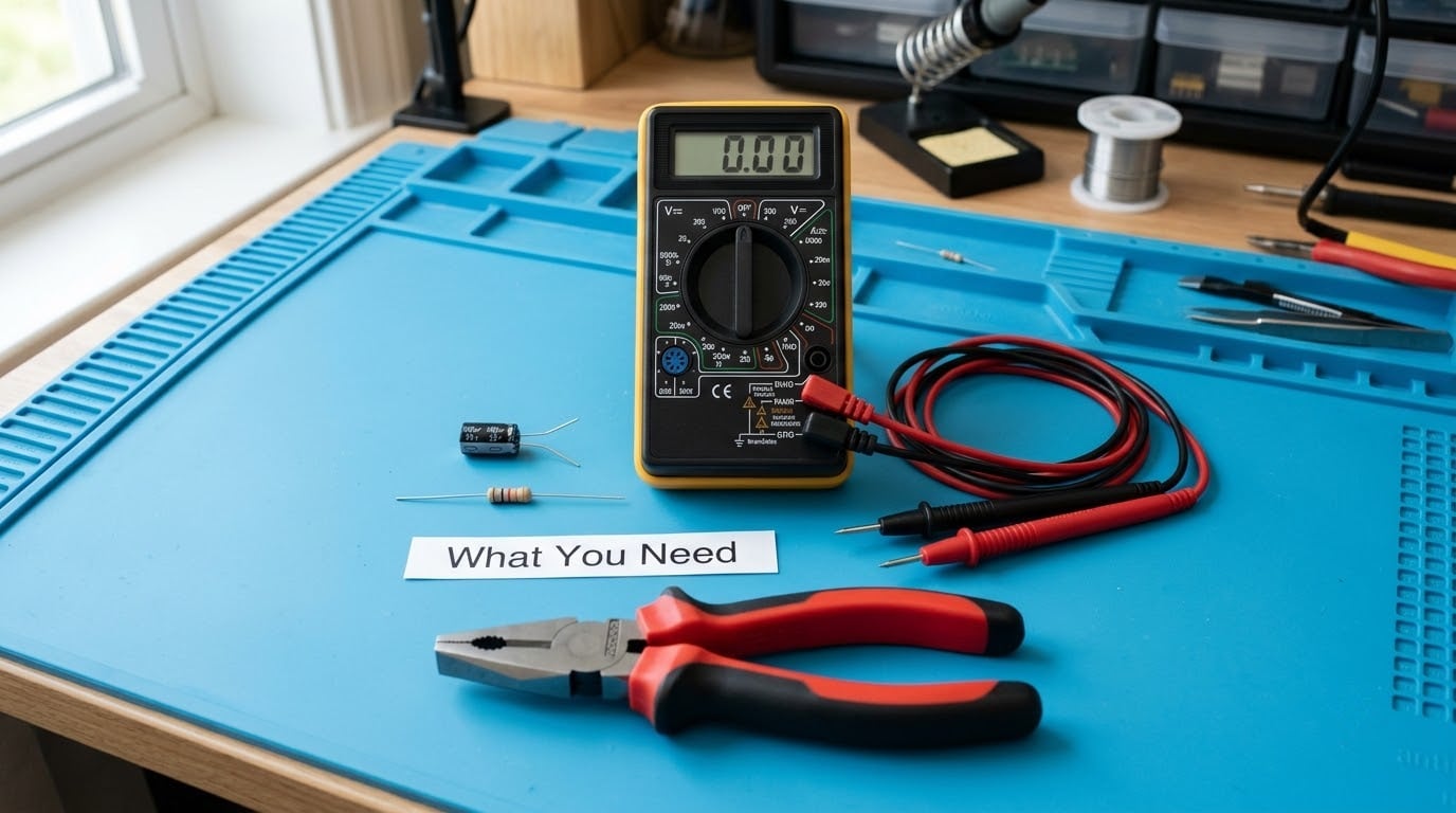
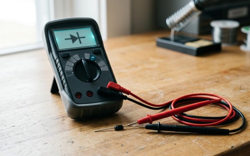
A multimeter with a capacitance setting is the main tool, and most mid-range digital meters added one years ago. Look for the diode-shaped capacitance symbol on the rotary dial, a range that covers microfarads, and a REL or zero button so you can cancel out stray capacitance in the leads.
A second meter option is the analog needle multimeter. It has no capacitance mode at all, but the charging behaviour of a capacitor shows up beautifully in resistance mode. For bench work, if you want deeper coverage of what a reference tool can do, our automated test equipment basics guide explains how automated measurement fits into a lab workflow.
A discharge resistor is the safety item people skip and then regret. A resistor between 1 kΩ and 10 kΩ, rated 2 W or higher, is a sensible default for capacitors up to a few hundred microfarads. For a microwave or CRT high-voltage capacitor, buy a purpose-built discharge tool with an insulated handle and never improvise.
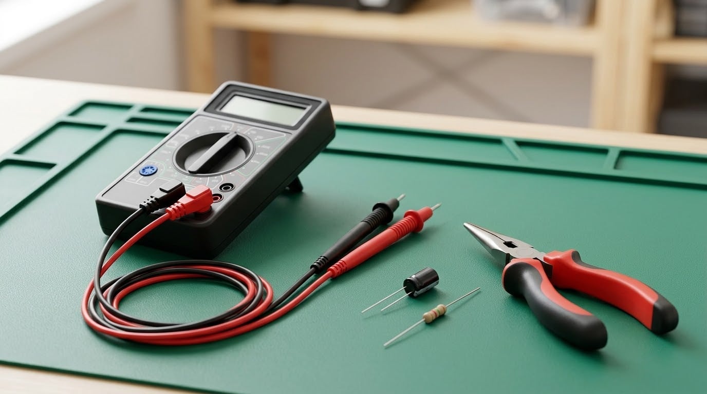
The rest is basic bench hygiene: safety glasses, insulated pliers or needle-nose for handling leads once a board is energized, an anti-static mat, and a few known-good capacitors of assorted values for comparison. Out-of-circuit testing is the reliable way, so budget for removing at least one leg of the part if you can.
How to Test a Capacitor with a Multimeter Step by Step
Identify the capacitor type, value, and voltage rating
Read the markings before you touch a probe. A radial electrolytic usually prints its value in microfarads and a voltage rating such as 25 V or 400 V, plus a tolerance letter and a temperature code. Ceramic and film parts are often unmarked and printed only on the tape or the bag they came in.
Polarity decides probe placement. Electrolytic and tantalum parts are polarized: the stripe on the sleeve marks the negative terminal, and the longer leg on a new part marks the positive one. Ceramic, film, paper and most surface-mount parts are non-polarized, so probe order does not matter.
Never test a capacitor on a meter or power supply set above its voltage rating. Higher voltage stresses the dielectric and can shift the value or, on a tired part, cause it to fail while you watch.
Disconnect power and discharge the capacitor safely
Unplug the equipment and discharge the capacitor before anything else. A charged electrolytic holds its voltage with almost no leakage, so it can hold enough current to injure you long after the device is off the wall.
Connect the discharge resistor across the capacitor terminals and leave it there for about five minutes. For larger values, wait ten. A rough time constant check works here: current falls to under 1 percent of its starting value after roughly five times the resistance-capacitance product.
Do not bridge the terminals with a screwdriver blade, even on a small board. That short is uncontrolled, and it spits sparks and metal fragments at the exact moment the capacitor is releasing its charge. Badcaps.net regulars and most repair manuals point at the same rule.
Verify the discharge with the meter on DC volts. A reading under about 0.2 V on a small capacitor is close enough to proceed. For a microwave high-voltage capacitor, treat five minutes as a minimum and measure before your hands go anywhere near it.
Set up the multimeter and check the test leads
Check the leads first, every time. Set the meter to the 200 Ω range, touch the probe tips together, and read zero — a figure in the low single digits is normal for a good pair. Lift them apart and the display should jump to OL.
If a lead reads OL while the tips are touching, that lead is broken. A broken lead on a resistance or capacitance test produces readings that look like a healthy component every time, which sends you hunting for a fault that is sitting in the probe in your hand.
For small capacitors, press REL with the probes touching before you measure. Meters commonly pick up 10 to 30 picofarads from the leads themselves, which is nothing on a 1000 µF part and everything on a 22 pF ceramic.
Test an electrolytic capacitor with a digital multimeter
Start in capacitance mode. Select a range above the expected value, connect the probes across the terminals with the red probe on the positive side, and keep them in place while the reading settles.
A good capacitor does one of two things depending on the meter: it prints a stable number close to the marked value, or it shows a shifting number that climbs and then slows. A streaming or wobbling display that never settles is itself a warning sign, because it points to high leakage.
The fault signatures are unmistakable. A reading of zero or near zero, or an immediate OL with no charging behaviour at all, means the part is shorted or open and should go in the bin. A steady reading well below the marked value means loss of capacitance.
There is no need to interpret a resistance-mode charging curve when the meter has a capacitance function. The one exception is a leakage check: leave the probes connected for a minute and watch whether the value drifts. Real capacitors slowly lose charge; a leaking one keeps drawing current.
Test a capacitor with an analog multimeter
Set the analog meter to the highest resistance range, usually 20 kΩ, and zero it. Ohmmeters work by pushing a small current through the part under test, so the deflection you see is that current meeting the capacitor’s changing impedance.
A healthy capacitor makes the needle sweep from the open end of the scale toward centre and then drift slowly back toward open as it charges. The needle never pins at zero for long. That sweep, however far it travels, is the signal you are looking for.
Needle behaviour maps to faults directly. A sweep that jumps straight to full scale and stays pinned at zero indicates a shorted capacitor. No movement from the open end at all indicates an open capacitor or a broken connection. A sweep that comes back down but leaves the needle stuck partway up points to leakage.
Swap to a higher resistance range for large electrolytics, where a slow charge time can make a good part look open on the 200 Ω setting. Low ranges act like heavy leakage and trick the needle into pinning at zero.
Use capacitance mode when the meter supports it
Capacitance mode is the most direct method and the one to reach for first. Rotate the dial to the symbol that looks like a capacitor schematic, two plates with one curved, or a double arrow above a capacitor, then pick a range that brackets the expected value.
Hold the probes on the terminals until the reading stops moving, then write the number down. Compare it against the marked value while allowing for tolerance: K means plus or minus 10 percent, M means plus or minus 20 percent, and J means plus or minus 5 percent.
Real readings sit slightly off the print in normal operation. Large electrolytics typically measure 10 to 20 percent low when cold and come closer to nominal as they warm up, and ceramics shift with temperature and applied bias. Test frequency matters too — meters commonly measure somewhere between 100 Hz and 1 kHz, and DC bias can make a nominal 100 µF part read noticeably lower.
Numbers well outside tolerance are the signal to replace. An 80 µF reading on a 100 µF K-rated part is normal; a 30 µF reading on the same part is not.
Confirm an unclear result with a known-good comparison
When a reading sits in a grey area, put a known-good capacitor of the same type and value on the meter and compare directly. Same meter, same leads, same ambient temperature, and the difference between the two readings tells you far more than either number alone.
This is also how you rule out the meter. If a known-good 470 µF part reads high on your meter by the same amount every time, the meter has an offset or the leads need a REL zero.
Never infer that a capacitor is healthy because it reads correctly inside a powered circuit. A test on an energized board tells you about the whole network, and on this site the advice from repair forums is consistent: lift one leg, or lift the part, before drawing conclusions.
Common Mistakes
Most bad readings come from preparation, not from a bad meter. These are the errors that show up again and again.
- Testing an energized or charged capacitor. Unplug first, then discharge through a resistor and confirm near zero volts.
- Reversing the probes on a polarized part. Modern meters tolerate it for a short moment, but the reversed voltage is exactly what a polarized capacitor dislikes. Red probe to the positive terminal, always.
- Leaving the capacitor soldered in. Parallel paths through neighbouring parts distort the reading in both directions. Lift one leg.
- Using too low a resistance range. A 200 Ω setting on a large electrolytic can pin the needle and look like a dead short. Start high and work down.
- Reading a resistance value as if it were capacitance. Ohms output is not microfarads. Only capacitance mode gives you a number in µF.
- Expecting an exact match to the printed value. Tolerance, temperature, test frequency and DC bias all move the number. Use the tolerance band.
- Trusting a reading from a suspect probe lead. Verify the leads against a known-good source before blaming the component.
One more trap worth naming: a capacitor can read its full rated capacitance and still be bad. High equivalent series resistance passes a capacitance test but sags under load, which is why board-level repair people on badcaps.net and thegearpage.net reach for an ESR meter once capacitance looks fine. For a single out-of-circuit part, a low reading, a short, or an open is as far as a multimeter takes you.
Frequently Asked Questions
Can you use a multimeter to check a capacitor?
Yes. A multimeter with a capacitance mode gives you the measured value in microfarads, and almost any multimeter can show the charging behaviour in resistance mode. Discharge the part, connect the probes, and compare the reading with the value printed on the sleeve. For high-ESR faults or in-circuit diagnosis, an ESR meter is the next step up.
What is the symbol on a multimeter for testing a capacitor?
Look for a symbol resembling a capacitor schematic: two parallel plates, one straight and one curved, or a double arrow above a small capacitor shape. It sits near the diode and continuity symbols on the rotary dial. On the display, the unit appears as microfarads written as uF, nF for nanofarads, or pF for picofarads.
How to tell if a capacitor is shorted?
A shorted capacitor reads about zero ohms or shows 0 µF on a capacitance meter, and on an analog needle meter it pins to full scale and stays there. On a digital meter in resistance mode the display drops to a near-zero value and holds it. A continuity beep that stays on across the terminals is the same fault in another form.
What are the two typical signs that a capacitor is bad or has failed?
The first is physical: a bulging or domed sleeve, leaking electrolyte, crust around the base, or a burnt smell. The second is electrical: a capacitance reading far below the marked value, a reading pinned at zero, or no movement at all. Many failures are visible on a good-lit bench before a single probe touches the part.
Why does my multimeter show OL when testing a capacitor?
OL means the resistance is higher than the meter can measure, which is normal for a healthy capacitor before it charges. Watch what happens next: a good part shows changing values, or an analog needle sweeps and drifts back. If OL never changes, the capacitor is open, or it is out of the range you selected, so switch to a higher range.
Can you test a capacitor without removing it from the circuit?
You can, but treat the result as a hint rather than a verdict. Parts in parallel with the capacitor add to the reading and parts in series reduce it, so a healthy board can read high, low, or unstable. Lift one leg to get a trustworthy answer, and remember that many board-level ceramic capacitors read as open in circuit because their contact area is tiny.
Conclusion
The safest order of operations is fixed: disconnect the power, discharge the capacitor through a resistor, verify zero volts, then measure. With the meter on capacitance mode you get a number to compare against the marked value and its tolerance band. Without that mode, watch the resistance sweep — charging behaviour means healthy, pinned at zero means shorted, no movement means open.
Replace the part when it is shorted, open, or well outside tolerance, and reach for an ESR meter when the capacitance reads fine but the circuit still misbehaves.