A capacitor code is a shorthand printed on the body of a component because there is no room for the full specification. On most small parts, three digits give you the capacitance, a trailing letter gives tolerance, and a separate number gives the voltage rating. Learning how to read capacitor codes and markings takes about ten minutes of practice, and it is the difference between swapping the right part and putting a reversed electrolytic across a 12 V rail.
This guide covers through-hole, SMD, ceramic, film, electrolytic and tantalum parts, plus the older colour-band style you still meet on restoration work. No product recommendations, just the decoding method.
Table of Contents
- What You Need
- Step-by-Step: How to Read Capacitor Codes and Markings
- Step 1: Identify the capacitor type
- Step 2: Read the capacitance value
- Step 3: Decode tolerance, voltage, and temperature codes
- Step 4: Apply the markings to a circuit
- Common Capacitor Code Systems and Worked Examples
- How to read capacitor codes and markings on film, tantalum and vintage parts
- Common Mistakes
- Frequently Asked Questions
- Can you measure capacitors with a multimeter?
- What value is a 472 capacitor?
- What is the code for a 0.1 uF capacitor?
- What does the 104 marking on a capacitor mean?
- Can I replace a capacitor with a higher voltage rating?
- How do I identify an SMD capacitor with no markings?
- Conclusion
What You Need
You can decode most capacitors with very little equipment. A 10x loupe or a phone camera held close is enough for through-hole parts, and you will need a steady light source because the print is often silver on black.
- A magnifier — a 10x loupe, a jeweller’s loupe, or the macro mode on your phone. Most SMD markings are under 1 mm tall.
- A datasheet or the manufacturer’s marking guide — required for letter codes, which are not standardised across brands.
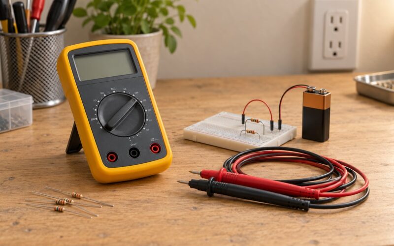
- A multimeter — a basic capacitance mode is enough for a rough check. An LCR meter gives you ESR and in-circuit-capable readings.
- A resistor and solder-free breadboard — only if you want to verify a value before fitting it.
- ESR meter — optional, but the only practical way to spot a leaking electrolytic on a populated board.
Keep a small notebook of the codes you decode. Six months later you will not remember what 4R7 means, and the notebook takes ten seconds.
Step-by-Step: How to Read Capacitor Codes and Markings
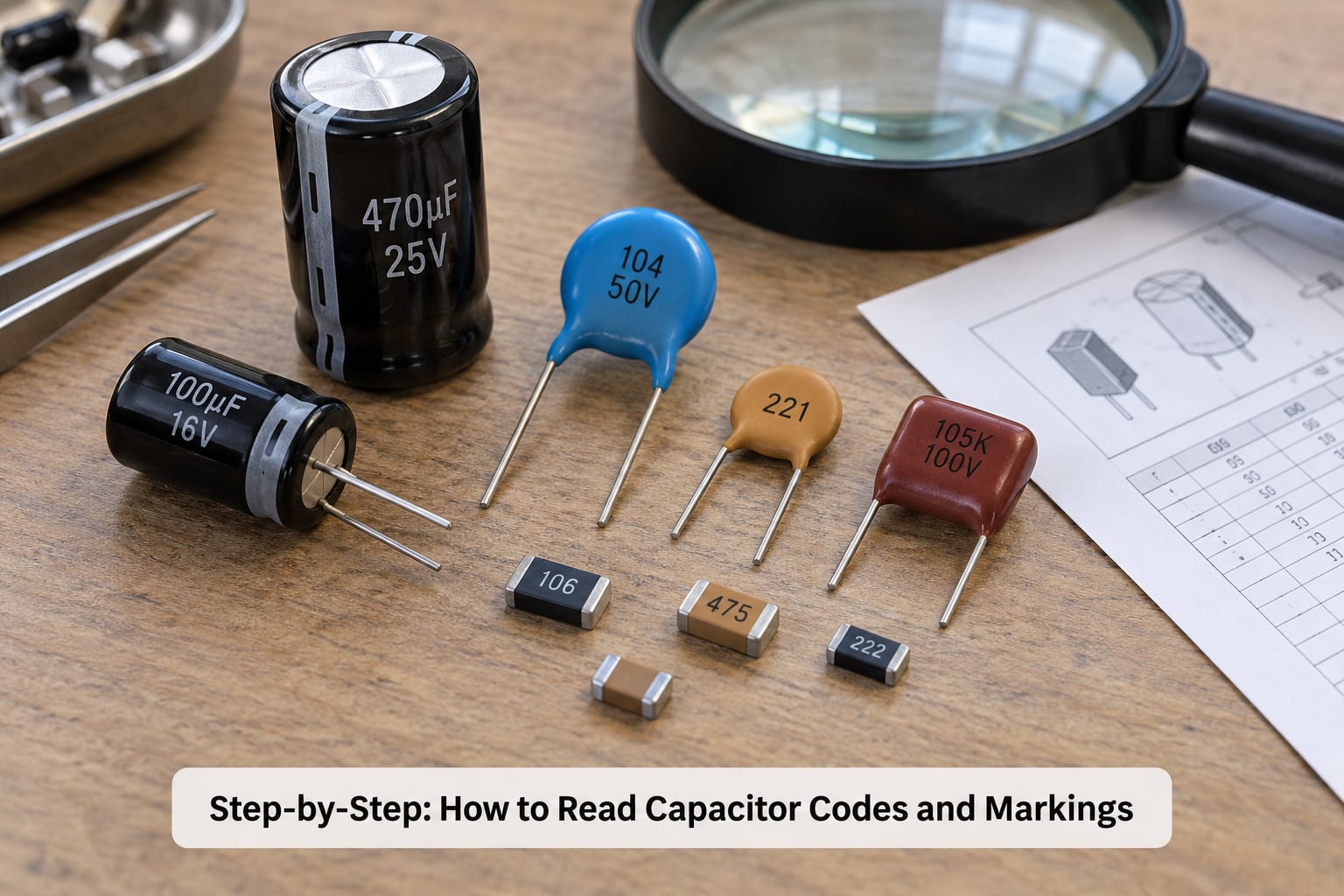
The order matters. Work outside in: identify the family, read the value, then read everything else. Most decoding mistakes come from skipping the first step and applying the resistor colour code to a capacitor, or from assuming a printed string means the same thing on two different manufacturers’ parts.
Step 1: Identify the capacitor type
Look at the body before you look at the numbers. Ceramic parts are usually a flat disc or a tan, yellow, brown or blue rectangular SMD block with no polarity marks. Electrolytic parts are cylindrical cans in aluminium, often with a black sleeve printed with stripes. Tantalum bead parts are small, shaped like a drop, and marked with a polarity band. Film parts are rectangular boxes with flat tops, common in snubbers and motor circuits.
Polarity tells you the family. A white stripe with minus signs down the side of a can is an aluminium electrolytic, and the stripe marks the negative terminal. A ceramic disc with painted edges is usually non-polarised, so it can go in either way.
Two physical clues confirm it on unmarked parts: the longer leg on a new radial electrolytic is the positive side, and a bulge or a leaked crust at the base of a can means the part is already dead, whatever the print says.
Step 2: Read the capacitance value
Most ceramic and film capacitors carry a three-digit EIA code. The first two digits are significant figures, the third is the multiplier, and the result is always in picofarads. A three-digit code never gives you microfarads directly.
So 104 reads as 10, then multiply by 10 to the power of 4, giving 100000 pF, which is 100 nF or 0.1 microfarads. 472 reads as 47 times 100 pF, which is 4700 pF or 4.7 nF. 223 is 22 times 1000 pF, so 22 nF.
Anything below 100 pF usually uses a two-digit code, and smaller values get the letter R used as a decimal point. That means 4R7 is 4.7 microfarads, 4n7 is 4.7 nanofarads, and 2R2 is 2.2 microfarads. The letter tells you which unit sits after the digits.
Electrolytics usually skip the code entirely and print the value directly, as in 470uF 25V. When you see an explicit unit, that unit wins over any code logic.
Step 3: Decode tolerance, voltage, and temperature codes
A tolerance letter follows the value code on through-hole parts. J means plus or minus 5 percent, K is plus or minus 10 percent, M is plus or minus 20 percent, and Z is a loose plus 80 minus 20 percent used in older audio gear. Precision film parts go tighter, with F at plus or minus 1 percent and B at plus or minus 0.1 percent.
The voltage rating appears as a plain number with a V, or as a two-part code. Markings like 16V or 50V need no translation. On EIA-style surface mount parts, a single letter before the value encodes voltage: A is 10 V, C is 16 V, D is 20 V, E is 25 V, G is 35 V, H is 50 V, and J is 63 V. Voltage codes vary between manufacturers, so treat the datasheet as the authority rather than the table.
Ceramic parts usually give temperature behaviour instead of tolerance, in the familiar X7R or Y5V form. The first letter sets the temperature range, the number sets the maximum capacitance change across that range, and the last letter is the tolerance. X7R runs from minus 55 to plus 125 degrees Celsius with up to plus or minus 15 percent drift. Y5V runs from minus 30 to plus 85 degrees Celsius but can lose over 80 percent of its rated value, which is why it stays in decoupling positions.
C0G, sometimes written NP0, is the opposite: plus or minus 30 parts per million per degree with no drift at all. You will find it in timing and resonant circuits where a drifting value breaks the design.
Step 4: Apply the markings to a circuit
Turn the decoded number into a real value in the unit the schematic uses, then check three things before you fit anything. The voltage rating must meet or exceed the voltage across the part in the circuit, with headroom for transients. The capacitance must match what the circuit expects, and tolerance matters more in timing circuits than in a power filter. And for any polarised part, the negative terminal has to land on the side the board expects.
One thing that catches people out with modern ceramics: DC bias. A 10 microfarad 0805 X7R part rated at 25 V can measure well under 6 microfarads at 5 V, and the drop gets worse with a smaller case size. That is normal physics, not a bad part. If your circuit depends on a real 10 microfarads at a working voltage, buy a larger case, a higher voltage rating, or change to electrolytic.
When substituting, a higher voltage rating of the same type is normally fine because the case simply gets a little larger. Changing capacitance in a timing circuit changes the timing, and changing dielectric changes the behaviour, so keep both the same unless you know why you are changing them.
Common Capacitor Code Systems and Worked Examples
This is the table I keep open in a browser tab. Nearly every code you meet on a small ceramic or film part is in here.
| Code | Read as | Value |
|---|---|---|
| 101 | 10 × 101 pF | 100 pF |
| 102 | 10 × 102 pF | 1 nF |
| 103 | 10 × 103 pF | 10 nF |
| 104 | 10 × 104 pF | 100 nF / 0.1 microfarads |
| 105 | 10 × 105 pF | 1 microfarad |
| 121 | 12 × 101 pF | 120 pF |
| 182 | 18 × 102 pF | 1.8 nF |
| 223 | 22 × 103 pF | 22 nF |
| 272 | 27 × 102 pF | 2.7 nF |
| 332 | 33 × 102 pF | 3.3 nF |
| 472 | 47 × 102 pF | 4.7 nF |
| 473 | 47 × 103 pF | 47 nF |
| 474 | 47 × 104 pF | 470 nF |
| 475 | 47 × 105 pF | 4.7 microfarads |
| 106 | 10 × 106 pF | 10 microfarads |
Tolerance codes on through-hole parts follow the value.
| Letter | Tolerance |
|---|---|
| B | plus or minus 0.1 percent |
| C | plus or minus 0.25 percent |
| F | plus or minus 1 percent |
| G | plus or minus 2 percent |
| J | plus or minus 5 percent |
| K | plus or minus 10 percent |
| M | plus or minus 20 percent |
| Z | plus 80 / minus 20 percent |
Ceramic dielectrics tell you about temperature and tolerance together.
| Code | Temperature range | Capacitance change |
|---|---|---|
| C0G / NP0 | minus 55 to plus 125 degrees Celsius | plus or minus 30 ppm per degree, no drift |
| X7R | minus 55 to plus 125 degrees Celsius | plus or minus 15 percent |
| X5R | minus 55 to plus 85 degrees Celsius | plus or minus 15 percent |
| Y5V | minus 30 to plus 85 degrees Celsius | plus 22 / minus 82 percent |
How to read capacitor codes and markings on film, tantalum and vintage parts
Film capacitors in box packages usually print the value plainly, as in 100n 63V, with an M or K tolerance letter. Precision film parts sometimes use the four-digit code instead, where the first three digits are significant and the fourth is the multiplier, so 2233 reads as 22 times 10 to the power of 3 pF, which is 22 nF.
Tantalum bead parts follow a similar idea. A number such as 106 gives 10 microfarads, and the following letter encodes voltage, commonly A for 10 V, B for 16 V, C for 25 V, D for 35 V and E for 50 V. A third letter, usually T or P, identifies the dielectric type. Because letters differ between makers, read the datasheet before you order replacements.
Handle a failed or suspect tantalum with care. When these parts short, they get very hot fast, and the result is a charred board. Never fit one in a circuit where reverse voltage is possible.
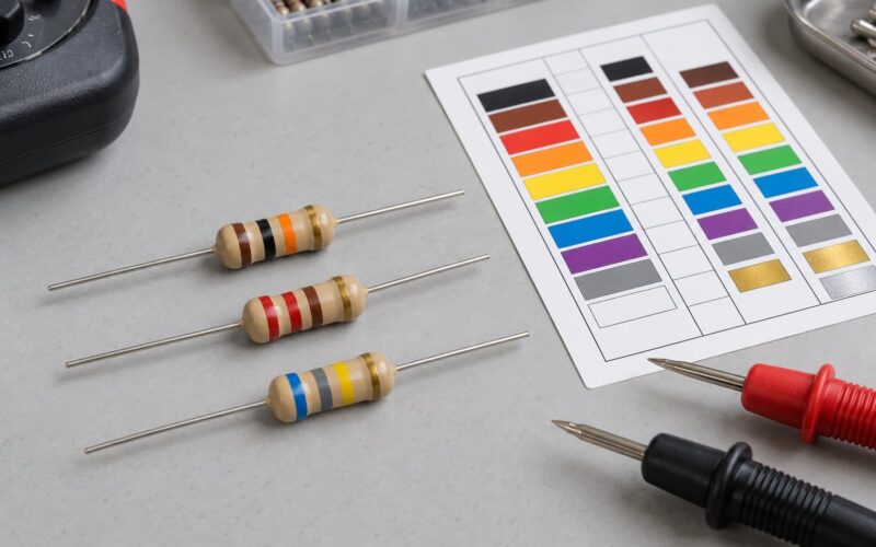
Older parts use colour bands in the same style as resistors: colour as digit, tolerance as gold or silver, and a final multiplier band read as picofarads. Black is 0, brown 1, red 2, orange 3, yellow 4, green 5, blue 6, violet 7, grey 8 and white 9. So orange, red and a yellow multiplier on a square film part in a restored amplifier gives 32 times 10 to the power of 4 pF, which is 320 nF, with a gold band after it for the tolerance.
Common Mistakes
Mixing up pF, nF and microfarads is the classic error. The multiplier digit only tells you where the decimal point lands if you know the unit, and the unit is always picofarads for a bare three-digit code.
Using the resistor colour code on a capacitor gives a number that is off by orders of magnitude, because the same bands mean ohms on a resistor and picofarads on a capacitor.
Ignoring voltage leads to the most dramatic failures. A part marked 6.3 V on a 12 V rail heats up, leaks, and eventually vents. Staying at or above the working voltage is the fix, with 50 percent headroom as a sensible habit on mains-adjacent rails.
Fitting a polarised capacitor backwards is worse. On an aluminium electrolytic, reverse voltage destroys it in seconds. Check the stripe on the can against the silkscreen plus mark on the board, and check the shorter leg when the part is new.
Treating a manufacturer’s internal code as a standard value causes confusion on parts like a 33 microfarad can that carries a batch code alongside its value. Read the number with the unit symbol and ignore the rest.
Trusting an in-circuit meter reading is the last trap. A capacitor measured while still soldered in reads in parallel with everything around it, and neighbouring parts can make the number meaningless. Lift one leg, or discharge and desolder, before trusting the figure.
Frequently Asked Questions
Can you measure capacitors with a multimeter?
Yes, most modern multimeters have a capacitance range that reads small electrolytics directly. Charge a capacitor, select the smallest range above your expected value, and connect the probes. A healthy part shows the value plus a few percent. On circuit boards, lift one leg first, because surrounding components distort the reading. LCR meters add ESR, which is the better test for a leaking electrolytic.
What value is a 472 capacitor?
A 472 code means 47 times 10 to the power of 2 picofarads, which is 4700 pF or 4.7 nF. The last digit is the multiplier, not part of the value. If the part is marked 472 rather than 472 pF, treat the picofarad figure as correct and check whether the body is a ceramic or film part, since a 4.7 microfarad part would normally print a decimal point or an R.
What is the code for a 0.1 uF capacitor?
You are looking for 104. The first two digits give the significant figures, 10, and the last digit is the multiplier, 4, meaning 10 times 10,000 picofarads. That equals 100,000 pF, which is 100 nF or 0.1 microfarads. A 104 is the standard value used for decoupling on most logic rails.
What does the 104 marking on a capacitor mean?
It means 100 nanofarads, also written as 0.1 microfarads. Read the first two digits as significant figures and the third as a power of ten multiplier, with the result in picofarads. So 104 becomes 10 times 10 to the power of 4, or 100,000 picofarads. Many parts also print 104 with a voltage figure and tolerance letter alongside it.
Can I replace a capacitor with a higher voltage rating?
Usually yes, as long as the capacitance and type stay the same. A higher voltage part is physically slightly larger, which matters only in tight layouts. Keep the capacitance identical in timing and resonant circuits, where the value sets the timing. You can often go up modestly for a decoupling part, but check the DC bias effect because a smaller case with a higher voltage rating can lose more of its rated capacitance in service.
How do I identify an SMD capacitor with no markings?
You cannot read it, because there is nothing printed, so use a meter instead. An LCR meter or a capacitance-capable multimeter, with one end lifted from the board, will give you the value directly. Size, package colour and circuit position narrow the guess: tiny 0402 and 0603 parts near a power pin are almost always a small ceramic decoupling capacitor. Measuring is far quicker than searching by part number.
Conclusion
Start with the family. Shape and polarity marks tell you whether you are holding a ceramic, an electrolytic, a film or a tantalum, and that decides how the rest of the marking should be read.
Then read the value code: two significant digits, one multiplier digit, answer in picofarads. Convert to the unit the circuit works in, confirm the voltage rating is high enough, check the tolerance where timing accuracy matters, and match polarity before the soldering iron is hot.