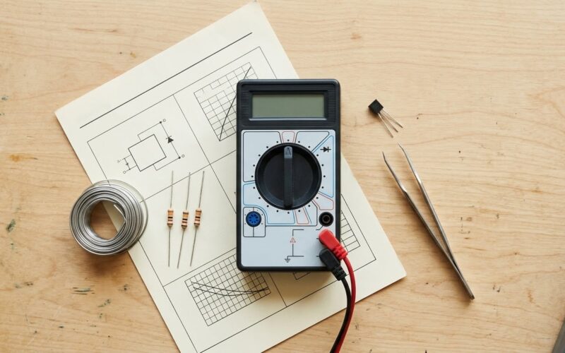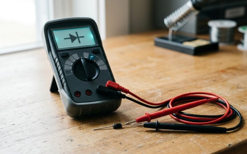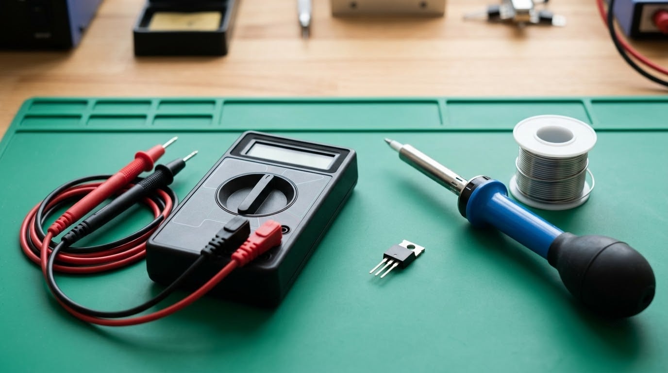
To test a MOSFET with a multimeter, set the meter to diode mode, discharge the gate by shorting it, then measure between drain and source in both directions. A healthy power MOSFET shows a forward drop of roughly 0.4 V to 0.7 V in one direction only, and open circuit (OL) when the probes are reversed. It takes about two minutes per device once you know which pin is which.
The catch is that a multimeter cannot tell you everything about a MOSFET. It confirms a shorted or open device, but it will not measure on-resistance, transconductance, or gate leakage properly. What it can do is rule a device in or out in seconds, which is exactly what you want before you order a replacement or condemn a whole board.
Table of Contents
- What You Need
- Step-by-Step: How to Test a MOSFET With a Multimeter
- Identify the MOSFET terminals
- Set up the MOSFET for testing
- Test the body diode
- Check resistance or capacitance
- Check for a shorted MOSFET
- Interpret the final result
- Common Mistakes
- Frequently Asked Questions
- What multimeter readings indicate a good MOSFET?
- Can I test a MOSFET without removing it from the board?
- Which multimeter mode should I use to test a MOSFET?
- Can I test a MOSFET with an analog multimeter?
- Why does my MOSFET show continuity between drain and source?
- What actually kills MOSFETs in a circuit?
What You Need
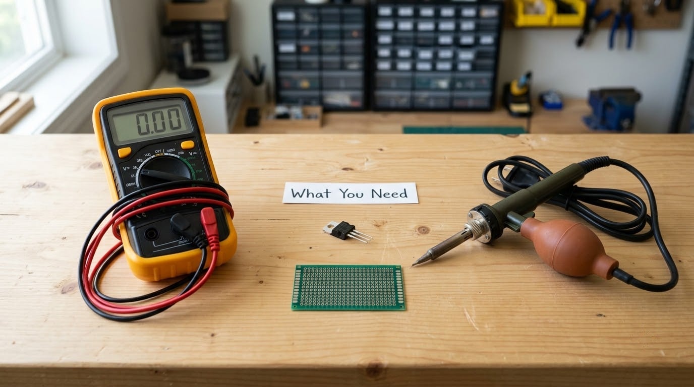
A digital multimeter with a diode test function is the one tool you actually need. Everything else is convenience. Almost every meter sold in the last decade has diode mode; on a budget meter it is usually a single button marked with the diode symbol, and it outputs somewhere between 1.5 V and 3.3 V.
That test voltage matters more than people expect. The meter’s diode mode applies a small current between its probes, and that voltage has to be high enough to charge the gate through the gate oxide to switch the channel on. If it is not, you will see OL on a perfectly healthy device and throw away a working part.
- Digital multimeter with diode mode. Continuity mode works as a rough substitute but will not give you a forward voltage number.
- Fine probe tips or a pair of needle probes for SMD packages where the leads are a fraction of a millimetre wide.
- Anti-static mat and wrist strap if you are handling MOSFETs outside a grounded bench. Gate oxide failures are not a myth.
- Desoldering iron, braid or a hot air station if the part has to come off the board.
- The datasheet for the part number. Pinouts genuinely differ between packages, and the physical look of the device tells you almost nothing on its own.
Remove the MOSFET from the circuit whenever you can. Every reliable result I have had came from a loose device on the bench, and almost every confusing result came from a part still soldered into a board full of resistors, diodes and parallel paths.
If you want the wider picture on what test gear is doing behind the readings, automated test equipment basics for beginners covers the instruments used once a bench goes past a handheld meter.
Step-by-Step: How to Test a MOSFET With a Multimeter

Identify the MOSFET terminals
Find the datasheet for the exact part number before you touch a probe. For a TO-220 package the three leads are, viewed from the front with the text facing you, usually gate, drain, source from left to right, and the metal tab is internally connected to the drain. On an SOT-23 or SOT-23P the pins are usually gate, source, drain in one arrangement and gate, drain, source in the other, which is exactly why guessing causes so many wrong conclusions.
Two physical clues help when the datasheet is missing. The body diode test itself will identify the source and drain pair for you once you know the direction that conducts, and the gate is normally the lead sitting alone on one side of the package. If the marking on the part is unreadable, treat the device as unknown and do both directions on every pair.
Set up the MOSFET for testing
Disconnect all power and wait for the bulk capacitors to discharge properly. A supply that still holds charge will give you nonsense readings and can damage the meter. If the circuit uses a gate driver, the driver output can sit near the rail and back-feed the gate through protection diodes, which is another reason to lift the part.
Discharge the gate by touching the shorted tips of a pair of tweezers, or a probe held against the source, across gate and source. The gate is a capacitor separated from the rest of the device by a thin oxide layer, and a charged gate can hold the channel partly on and make a healthy part look leaky. Doing this first removes one of the most common false positives.
Test the body diode
This is the check that actually works. Every MOSFET has a parasitic diode between source and drain, formed by the substrate junction, and it behaves like a normal silicon diode.
- Set the multimeter to diode mode.
- For an N-channel MOSFET, put the black probe on the drain and the red probe on the source.
- Expect a reading between about 0.4 V and 0.7 V. Many silicon power devices sit closer to 0.5 V to 0.6 V.
- Swap the probes. Expect OL or a reading above the meter’s range.
- For a P-channel MOSFET the polarity is reversed: red on the drain, black on the source gives the forward drop, and the other direction is open.
A Schottky-body MOSFET may read noticeably lower, around 0.3 V, and that is still a pass. What matters is that one direction conducts as a diode and the other does not.
Here is what the result means:
| Reading, probe A to probe B | Reading, probes reversed | Verdict |
|---|---|---|
| 0.4 V to 0.7 V | OL | Healthy body diode |
| 0.3 V (Schottky body) | OL | Healthy, note the lower forward drop |
| OL | OL | Open device or wrong pin identification, recheck the pinout |
| 0.000 V to 0.2 V | 0.000 V to 0.2 V | Shorted drain to source, device is dead |
| 0.3 V | 0.3 V | Shorted or severely leaky device |
Check resistance or capacitance
Set the meter to resistance and measure gate to source, then gate to drain. A healthy part will show OL, a very large resistance, or a number that climbs as the gate charges. That climbing behaviour is the gate capacitance being charged by the meter’s test current, and it is normal. An analog meter shows it as the needle sweeping across the scale and slowly drifting back.
A steady reading of a few hundred ohms or less between gate and source is not normal. That is gate oxide leakage or a shorted gate, and it will not recover.
The catch here is test voltage. A meter with roughly 2 V of diode test voltage may not fully enhance a standard-level device such as an IRFZ44N, whose threshold voltage is specified up to about 4 V. Low threshold parts like the AO3413 or most logic-level parts will switch under a 3 V meter, so a standard-level device can read OL and still be fine. If you suspect this is the problem, charge the gate by touching it with a probe and then measure drain to source, or test the device on a powered circuit where the gate is driven properly.
Check for a shorted MOSFET
Test all three terminal pairs in both probe directions, six measurements in total. This catches the failure that actually kills power devices: a shorted drain-source channel that lets full current through regardless of the gate.
A consistently near-zero reading in both directions across source to drain means the device is shorted. The same reading from gate to source or gate to drain means the gate oxide has failed. Either way the part goes in the bin.
Interpret the final result
A healthy power MOSFET gives you OL or a changing value at the gate, a one-way diode reading between drain and source, and no continuity anywhere in both directions. That is the full signature of a working device as far as a multimeter is concerned.
An open body diode with OL in both directions is usually a misidentified pin or a device that has failed completely. In-circuit, parallel paths cause this all the time: a diode across the source to drain rails, or a winding resistance of a few ohms in a motor or transformer circuit, will mask the reading completely. Treat any in-circuit result as a screening test, not a verdict.
To charge the gate, hold a probe between gate and source for a moment, then move the red probe to the drain and the black probe to the source. If the resistance now collapses to a low value, the channel turns on and the part is good. This works on logic-level parts almost every time. It can fail to work on high-threshold devices simply because the meter cannot supply enough voltage, so a negative result here is not proof of failure.
Common Mistakes
Testing a powered circuit. A live board can blow a meter fuse and will give readings that mean nothing. Unplug, discharge, then test.
Skipping the gate discharge. A charged gate makes healthy devices look leaky, which sends good parts to the scrap bin. Short gate to source first, every single time.
Treating resistance range as a final answer. Resistance mode is for quick screening only. It applies an unknown test voltage and tells you nothing about the on-resistance you care about.
Assuming source and drain can be swapped. The body diode is not symmetric. If you reverse the expected polarity, a healthy device looks open, and you replace a part that works.
Assuming every package has the same pinout. SOT-23 comes in at least two incompatible orders. Read the datasheet.
Calling a device dead from an in-circuit reading. Surrounding components change everything. If the reading is odd and the part matters, lift one leg and retest before condemning it.
Ignoring the meter’s test voltage on logic-level parts. A standard 3 V meter cannot switch a device rated for 10 V and 15 V gate drive. Report the limitation rather than the failure.
Frequently Asked Questions
What multimeter readings indicate a good MOSFET?
A good MOSFET reads about 0.4 V to 0.7 V in one direction between drain and source and open circuit (OL) with the probes reversed. Gate to source and gate to drain should read OL, a very high value, or a number that climbs briefly as the gate charges and then settles. Any near-zero reading in both directions between drain and source means the device is shorted and should be replaced.
Can I test a MOSFET without removing it from the board?
Yes, and it works as a first pass. Power off and discharge the board, then test drain to source in both directions. Remember that parallel diodes, coils or low-value resistors on the same rails will add their own readings and can mask the result. Any in-circuit test is a screening step. Lift at least one leg, or remove the part, before you conclude that a device has failed.
Which multimeter mode should I use to test a MOSFET?
Use diode mode as the primary test because it applies a small, controlled current and shows a forward voltage value. Continuity mode gives you a pass or fail beep but no number. Resistance mode is useful for spotting gate leakage and for watching gate capacitance charge on an analog meter. For anything beyond pass or fail, a curve tracer or semiconductor analyzer is the proper instrument.
Can I test a MOSFET with an analog multimeter?
You can, and it has one advantage: you can see the gate charging. Short gate to source, set the meter to the highest ohms range, and watch the needle sweep across the scale and drift back when you release. That movement is the gate capacitor charging, and it confirms the gate oxide is intact. Body diode testing is harder because analog meters rarely give a reliable forward voltage figure.
Why does my MOSFET show continuity between drain and source?
Two reasons, and the first is far more common. Check the pinout, because SOT-23 packages ship in two different gate, source and drain orders and reversing the body diode makes a healthy device look open, not shorted. If the reading really is near zero in both directions, the channel is shorted and the device is dead. Shorts come from voltage spikes, current spikes, or a failed gate letting the full rail across the channel.
What actually kills MOSFETs in a circuit?
Avalanche breakdown from drain voltage spikes is the biggest cause, usually a bad clamp or a missing snubber across an inductive load. Operating outside the safe operating area, running a hot device into thermal runaway, and back-driving the gate through protection diodes are close behind. A shorted gate oxide from an ESD strike or a miswiring mistake finishes devices off quietly. Check the surrounding parts too, since a failed gate driver or rectifier kills the MOSFET it drives.
Start with the body diode in diode mode, one direction at a time, after discharging the gate. If that reading is right and nothing shows continuity in both directions, the device is good for all practical purposes and you can fit it. If the reading is odd in-circuit, pull one leg and repeat before you order anything.