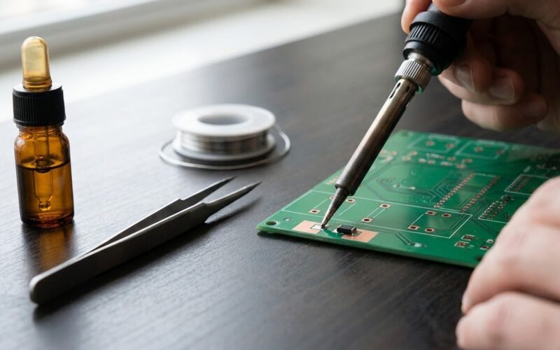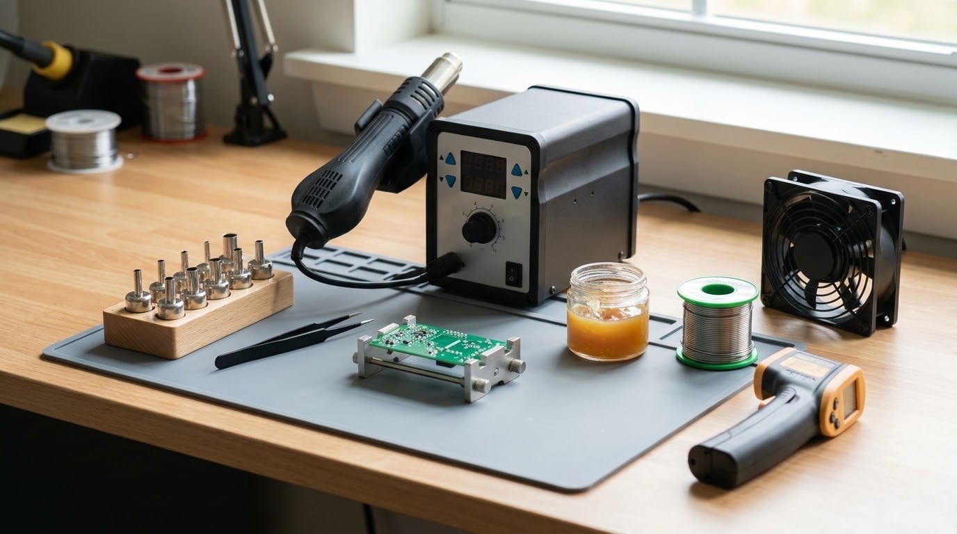
To use a hot air rework station, you heat the air in a temperature-controlled nozzle until the solder under a surface-mount part melts, then move the part with tweezers while it is still liquid. That is the whole technique. Everything else is prep work that keeps the board from lifting a pad or scorching a neighbour. A first job takes about 20 minutes once you have read this page.
I have watched a lot of people learn this the expensive way, heating a 0201 resistor until the pad underneath let go. The fix is boring and repeatable: low airflow, heat that moves, flux on the joints, and a steady hand. Start on a dead board from a bin before you touch anything you care about.
Table of Contents
- What You Need
- Tools and materials worth having on the bench
- Basic ESD and safety precautions
- Why there is no single correct temperature
- Step-by-Step: How to Use a Hot Air Rework Station
- 1. Inspect and Identify the Component
- 2. Prepare the PCB and Work Area
- 3. Set the Air Temperature and Airflow
- 4. Heat the Component Evenly
- 5. Lift or Remove the Component
- 6. Clean and Replace the Component
- 7. Inspect and Test the Repair
- Common Mistakes
- Temperature set too high
- Nozzle held too close or too still
- Moving too quickly
- Board not secured
- Skipping flux
- Heating neighbouring components
- Pulling before the solder is fully molten
- Skipping inspection
- Technique tips worth remembering
- Frequently Asked Questions
- What temperature should I set on a hot air rework station?
- Which nozzle size should I use?
- How do I stop hot air from damaging parts next to the one I’m removing?
- Can a hot air station remove through-hole parts and connectors?
- What do the S-E and H-E errors mean on a hot air station?
- Conclusion
What You Need
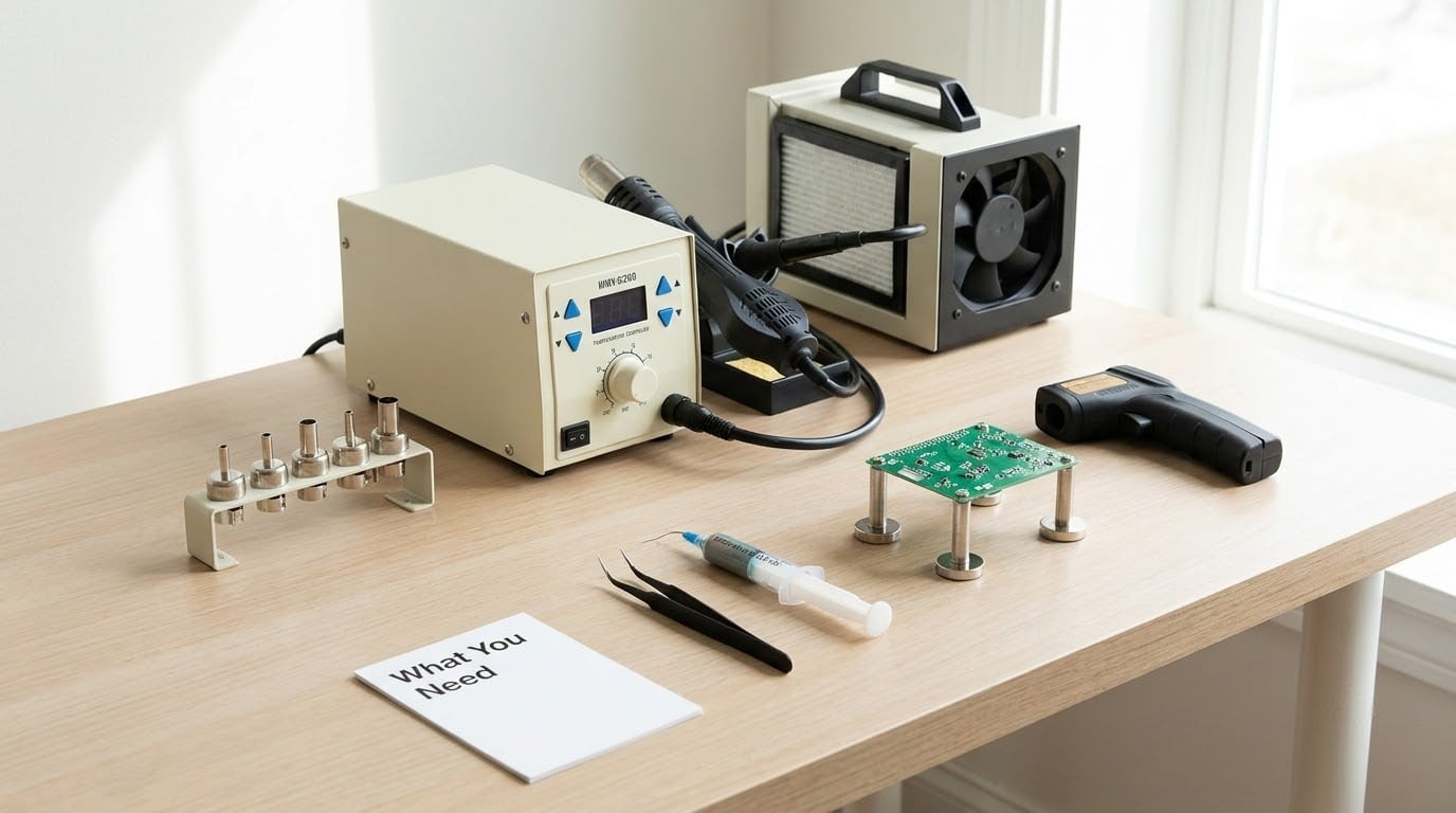
The core tool is a temperature-controlled hot air rework station: a heating element, a blower, and a handpiece that pushes heated air through a nozzle you swap depending on the part size. Station models differ, so follow your own unit’s manual for how it reports temperature and how its airflow scale is numbered.
Tools and materials worth having on the bench
- A hot air rework station with adjustable temperature and airflow. Digital temperature readouts are worth the difference, because guessing is what burns boards.
- Interchangeable nozzles in several sizes. A narrow tip concentrates heat on small parts; a wide tip spreads it across a multi-pin package so every joint melts together.
- ESD-safe tweezers for handling parts. Ceramic or anti-static plastic tips keep static away from the part while it sits on the board.
- Magnification — a stereo microscope or a loupe on a stand. Fine-pitch pins are smaller than you think at arm’s length.
- Solder paste and flux. Paste for placing new parts, no-clean or regular flux for helping existing joints flow. Flux is the single biggest reason a joint releases on command.
- Solder wick and a swab plus isopropyl alcohol to clean pads before and after.
- PCB supports — a vise, a third hand, or two folded card stand-ups. The board must not flex while you work on it.
- An extraction fan or fume extractor with a filter, plus a heat-resistant mat. Flux smoke is the reason ventilation matters here.
- An infrared thermometer, if you want to know what the surface near your joint is really doing.
Basic ESD and safety precautions
Ground yourself and the board. A wrist strap clipped to a proper ground point, or working on a grounded mat, keeps static off parts that would otherwise fail quietly weeks later.
Work on a heat-resistant surface with nothing flammable nearby, and keep the extraction fan running. Flux fumes set off sensitive fire alarms in apartments and offices, which is exactly the complaint that shows up again and again in electronics forums. Never point the hot nozzle at your face or fingers, and set the wand in its holder or on its rest, never on the bench where a rolling nozzle can scorch the surface.
Why there is no single correct temperature
There isn’t one number that works for every job. The right setting depends on the component, the board, the solder paste or wire you are using, and what the manufacturer of the board and the part specifies.
As a starting point that people on repair forums report working, roughly 270 to 280 °C suits leaded solder and roughly 350 to 380 °C suits lead-free solder. Lead-free needs the higher number because it melts at a higher temperature. Treat those as starting points to adjust, not as instructions to override a datasheet.
Step-by-Step: How to Use a Hot Air Rework Station
1. Inspect and Identify the Component
Work out what you are removing before you heat anything. A 0402 resistor or a small capacitor behaves very differently from a QFN IC, a plastic connector, or a ball grid array package.
Note polarity before heat touches the part: a diode band, a capacitor’s stripe, a dot or triangle on an IC, and pin one marked on the package or the board silkscreen. Read the package markings under magnification so you know the part type and can order a replacement. Also identify what sits within a few millimetres of the target, because neighbouring plastics, crystals, and sensors are what usually get destroyed.
Setting consideration: nothing yet. The inspection is what decides your nozzle size, so do not rush it.
2. Prepare the PCB and Work Area
Disconnect power. Remove the board from powered equipment entirely, take off the battery on mobile devices, and discharge any large capacitors if the design calls for it. A board that still has power can be destroyed by a static-free soldering iron too.
Secure the board on heat-resistant supports so it cannot flex or slide. Flexing a laminate separates the copper from the fibreglass, and that delamination cannot be undone. Clean the target area, then apply a small amount of flux, or a thin film of solder paste if you plan to place a new part directly onto the board.
Resting the board flat on a hot surface is fine for a second or two of warm-up, but do not park it there. Heat transfers unevenly through a table, and you lose the feedback you get from holding the nozzle yourself.
3. Set the Air Temperature and Airflow
Start conservative. Set the temperature for the solder you are dealing with — roughly 270 to 280 °C for leaded, 350 to 380 °C for lead-free — and set airflow low to mid range. Forum advice consistently lands around the middle of the airflow scale, which is enough to get heat into the joint without pushing parts around.
Airflow and temperature do opposite jobs on the same joint. More airflow moves heat away faster, which is how large ground planes absorb your heat. Too much airflow cools the joint so it never melts, and loose parts near the nozzle can lift and tumble. Too much temperature cooks the board, lifts pads, and cracks packages even when the solder does flow.
Let the station reach temperature and read the display before you approach the board. A stable reading means the thermocouple has settled. A station that swings 20 °C while it recovers is telling you its airflow is already at the limit.
4. Heat the Component Evenly
Hold the nozzle a few millimetres above the part and move it in a slow circle or small figure of eight. The motion matters more than the distance: constant travel spreads the heat across all sides so no single joint lags behind.
Keep the nozzle clear of adjacent components and out of contact with the board. Watch for the solder to look glossy and to slump on its own — that shine is the signal you want. Then add flux if the joint has gone still, since fresh flux often restarts the flow without extra heat.
If only one side of a multi-pin component moves, you are heating too locally. Switch to a wider nozzle, drop the height a little, slow the travel, and aim the airflow across the whole footprint so every pin warms at the same rate.
5. Lift or Remove the Component
Grab the part lightly with tweezers while the solder is still liquid, then lift straight up and away without twisting. Twisting snaps fragile leads and rips the pads underneath, and that is the single most common way people damage a board during removal.
Keep the nozzle moving while you manipulate the part. If you hold the heat on one spot while a tweezer hand is getting into position, you cook the opposite side of the board and can slump a ground pad.
Plastic connectors, ribbon connectors, and parts on large ground pours need a different approach: more airflow and a wider nozzle, because the copper is acting as a heat sink. Multi-pin ICs with an exposed pad may need a few passes to get all the legs molten before the part will release. A ball grid array under a heat spreader or CPU is a different job entirely, needing preheating from below and, usually, professional equipment.
6. Clean and Replace the Component
Clear leftover solder with solder wick and fresh flux while the board is still warm. Hold the wick in place with tweezers and press the iron or nozzle onto it, then lift both together. The pads should end up flat and clean with no solder ridges clinging to the edges, because a lumpy pad will hold the new part up and tilt it.
Align the replacement by polarity or pin-one marking and set it down with tweezers. For hand placement, a bead of solder paste on the pads lets you reflow without touching the iron to the part: heat the area until the paste flows and pulls the part into a centred, flat position, then let it cool without moving anything.
If you are tinning through-hole pads or reattaching leads, flow a little solder onto each joint instead. Keep the board stable while it solidifies; a part nudged while solder is setting will produce the classic tombstone shape that never quite seats.
7. Inspect and Test the Repair
Look at the work under magnification before power goes back on. You are checking for solder bridges between adjacent pins, missing solder on any joint, scorching or discolouration near the footprint, lifted or torn pads, leftover flux and debris, and correct orientation of the part you just placed.
A hot air pass leaves a residue that looks like a grey film and traps moisture, so clean the area with isopropyl alcohol and a swab while the board is still warm.
Then measure. A multimeter in continuity or resistance mode tells you more than guessing: no short across the rails, expected resistance values in place. Power the board up under controlled conditions — current-limited if you have it — and watch current draw and temperature. Follow the manufacturer’s instructions for the equipment where they exist, and treat a board that draws more than expected as a fault to investigate rather than something to keep powering.
Common Mistakes
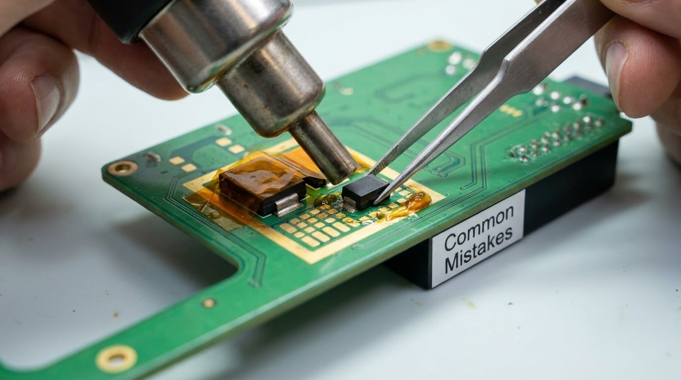
Nearly every ruined board I have seen traces back to one of these.
Temperature set too high
The solder melts fine, but so does the pad underneath and sometimes the laminate. Start at the conservative end of the range for your solder type and raise it only if the joint refuses to flow.
Nozzle held too close or too still
One hot spot cooks the board while the far side of the part stays solid. Keep a few millimetres of gap and travel in a continuous pattern.
Moving too quickly
A quick pass never brings the joint up to temperature; you just get uneven heating. Slow the hand down and count a few seconds per lap.
Board not secured
An unsecured board slides or flexes the instant you touch it. Solder pads tear before they lift when the board is allowed to move.
Skipping flux
Dry solder needs more heat, and more heat is what damages boards. Flux lowers the barrier so the same temperature works with less dwell time.
Heating neighbouring components
Plastics melt, crystals crack, and sensors drift long before the target part releases. Use a narrow nozzle, keep the heat centred, and shield what you can.
Pulling before the solder is fully molten
Tugging at a part that is only soft leaves a torn pad or a bent lead. Wait for the glossy slump, then lift straight up.
Skipping inspection
A bridge or a reversed part looks obvious under magnification and impossible without it. The ten seconds of looking saves the repair.
Technique tips worth remembering
- Work on scrap boards from dead electronics first. Removing and replacing 0402 passives builds the muscle memory faster than any tutorial.
- Preheat large boards or big copper areas from below when the top-side heat keeps stalling. A hot plate under the board balances the heat budget.
- Budget station clones often read a little high or low at the nozzle. Compare the displayed temperature against an infrared thermometer on the nozzle and note the offset for future work.
- Run the wand’s cool-down or auto-shutoff cycle before switching off, and put the nozzle in its holder every time you set the gun down.
Frequently Asked Questions
What temperature should I set on a hot air rework station?
Most people start around 270 to 280 degrees Celsius for leaded solder and 350 to 380 degrees Celsius for lead-free solder, which melts at a higher point. Treat those as starting points rather than fixed answers. The component, the board, the solder paste and the manufacturer’s datasheet all matter, and you should always check the board maker’s service guidance before applying heat to a densely packed assembly.
Which nozzle size should I use?
Match the nozzle to the footprint rather than to the part’s height. A narrow nozzle concentrates heat for 0402 and 0602 passives, a medium tip handles standard ICs and small connectors, and a wide flat nozzle is for multi-pin packages, connectors, and anything on a large ground pour. If only one side of a component melts, you are too small or too close. Step up a size and travel more widely.
How do I stop hot air from damaging parts next to the one I’m removing?
Use the smallest nozzle that still covers the target footprint, keep the nozzle a few millimetres above the board, and move it in a slow circle so heat spreads evenly instead of soaking one area. Low to mid airflow reduces mechanical stress on nearby parts. Protect adjacent components with a piece of aluminium foil or a spare piece of PCB held in tweezers, and add fresh flux to the target joint before adding any more heat.
Can a hot air station remove through-hole parts and connectors?
Yes. Desoldering through-hole joints and replacing USB, HDMI, or board-to-board connectors is one of the most common uses for the tool. The connector bodies are plastic, so keep airflow moderate, use a wider nozzle, and heat the full row of pins so everything releases together. Cooling solder blobs with solder wick afterwards keeps the new joint clean and gives the replacement somewhere to sit flat.
What do the S-E and H-E errors mean on a hot air station?
S-E reports a problem with the temperature sensor or its thermocouple connection, such as a loose or reversed lead. H-E indicates the heater has overheated or that airflow has dropped, commonly from a blocked or wound fan. Both codes point at airflow and sensor health before they point at the board you are repairing. Check the fan is spinning freely, the air inlet is clear, and the sensor wiring is seated before powering the station again.
Conclusion
Learn how to use a hot air rework station by slowing down at the two points that decide the outcome: identifying the component and choosing a conservative temperature for the solder you are working with. Set airflow low to mid, keep the nozzle moving, put flux on the joint, and lift straight up the moment the solder slumps.
Ventilation matters as much as technique. Run the extraction fan, work on a heat-resistant surface, practice on dead boards first, and finish with a magnified inspection and a controlled first power-up. When the board or equipment maker publishes rework guidance, follow it over anything you read here, including this page.