A pull-up resistor ties a signal line to your positive supply so the line reads logic high when nothing else drives it; a pull-down resistor ties the same line to ground so it reads logic low. That is the whole difference, and pull up vs pull down resistors explained in one sentence: both set a known default logic state so the input never floats. Choosing between them comes down to the pin’s active polarity and what is allowed to override the default.
I have spent enough time staring at scope traces of pins that randomly went high to know that a missing bias resistor shows up as a bug that reads like firmware. Twice on one board the “software fault” turned out to be a single unterminated enable line. Once you read the board with those defaults in mind, the pull-up vs pull-down decision stops being guesswork.
Table of Contents
- Pull-Up vs Pull-Down Resistors at a Glance
- What Are Pull-Up and Pull-Down Resistors?
- Pull up vs pull down resistors explained through the voltage divider
- How Does a Pull-Up Resistor Work?
- How Does a Pull-Down Resistor Work?
- What Logic State Do Pull-Up and Pull-Down Resistors Create?
- Where Are Pull-Up and Pull-Down Resistors Used?
- How Do You Choose the Resistor Value?
- Pull-Up vs Pull-Down Resistor Examples
- Common Problems and Design Mistakes
- Which Should You Choose?
- Frequently Asked Questions
- Can a pull-up and pull-down resistor be used on the same signal?
- Why does an I2C bus normally use pull-up resistors instead of pull-down resistors?
- Is a 10 kOhm pull-up resistor suitable for every digital input?
- Do input pins always need an external pull-up or pull-down resistor?
- Why does a pull-up resistor not cause a short circuit when the line is pulled low?
- Can pull-up or pull-down resistors replace series termination resistors?
- Conclusion
Pull-Up vs Pull-Down Resistors at a Glance
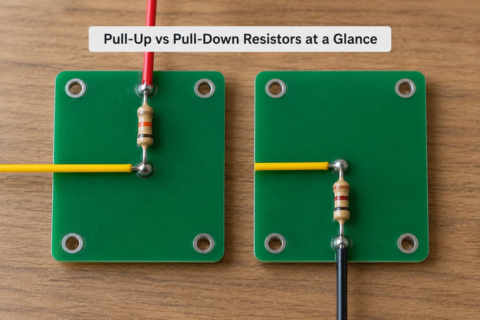
| Criterion | Pull-Up Resistor | Pull-Down Resistor |
|---|---|---|
| Connected between signal and | Positive supply, VCC | Ground |
| Default state when undriven | Logic high | Logic low |
| Current path while held active | VCC through resistor to ground | Ground through resistor to VCC |
| Used with open-drain devices | Standard, devices pull low | Rare, no defined idle high |
| Typical active-low convention | Reset, chip select, interrupt | Rare |
| Typical active-high convention | Rare | Enable, shutdown, gate drives |
| Button wiring | Button shorts to ground, press reads low | Button shorts to VCC, press reads high |
| Static current in default state | Near zero | Near zero |
| Static current while active | VCC divided by resistance | VCC divided by resistance |
| Prefer it when | The standard owns the idle-high state | You want a safe inactive default |
Both options draw almost nothing in their default state. The current question only matters while another device actively drives the line in the opposite direction.
What Are Pull-Up and Pull-Down Resistors?
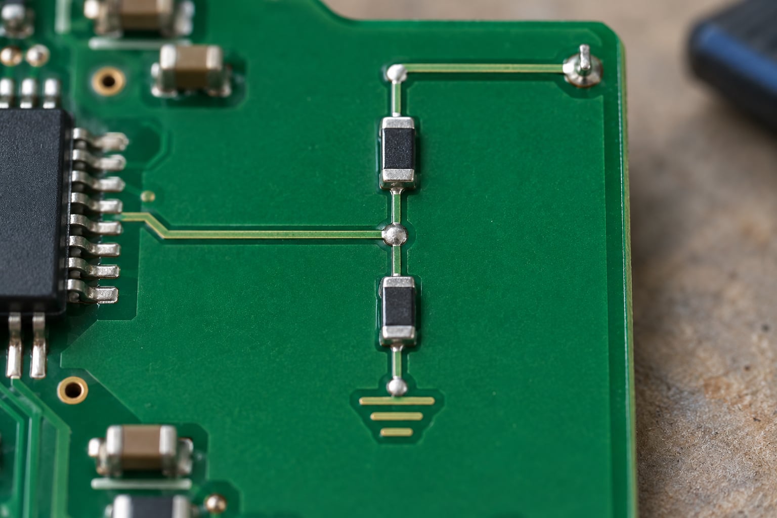
A pull-up resistor is a resistor from a signal line to the supply rail. A pull-down resistor is a resistor from a signal line to ground. Both are weak, they exist to hold one known logic level when every driver on the net has released the line.
The problem they solve is the floating input. A CMOS input has very high impedance, roughly a teraohm scaled to leakage in microamps. With no voltage source and no pull resistor, that impedance combined with stray capacitance lets the pin sit anywhere between the low and high thresholds. The pin is not at 0 V and it is not at VCC, it is undefined, and undefined regions invite coupling from nearby nets.
What you see on the bench is a pin that reads high at boot and low after you move the cable. Interrupts fire on their own. An enable line stays enabled after the device resets. Firmware written to handle “impossible” states ends up carrying code that masks a hardware default.
These are not current-limiting resistors. A series current-limiting resistor sits in line with the signal and shapes a load’s current. A pull resistor sits in parallel with the line and only conducts when something else pulls against it. Confusing the two leads to resistors that are ten times too small or too large.
Pull up vs pull down resistors explained through the voltage divider
Picture a pull-up of 10 kOhm feeding an input that leaks 1 microamp. The voltage drop across the resistor is 1 microamp times 10 kilohm, which is 10 mV, so the pin sits just under VCC. That small droop is fine. Raise the resistor to 1 MOhm with the same leakage and you drop 1 V, and a 3.3 V line now reads about 2.3 V, which on a 3.3 V part may sit below the input high threshold.
The same arithmetic explains why a pull-down fails on the other side. Leakage current flowing out of the input pulls the node below ground reference, so a high-impedance pull-down on a leaky line can drift out of the valid low region too.
How Does a Pull-Up Resistor Work?
A pull-up resistor connects VCC to the signal line through a resistance in the tens of kiloohm range. Nothing else connected, no current flows and the input reads logic high. That high is the resting state, and it is what the pin sees during reset, while the driving device is disabled, or while the line is in a high-impedance state.
Now let another device pull the line to ground. Current runs from VCC, through the pull-up, through the open-drain transistor or open-collector transistor, into ground. The pin reads low while that current flows. Release the line and the current stops, the node climbs back to VCC through the resistor, and the pin reads high again.
This is exactly how I2C works. Every device on the bus has open-drain or open-collector outputs. A device signals a zero by pulling SDA or SCL low and stays out of the way otherwise. The pull-up resistor is what makes the line return to high, and without it a released bus reads nothing at all.
A GPIO with the internal pull-up enabled behaves the same way, with the resistor sitting inside the chip instead of on your board. It saves a component, and it is usually too weak for a noisy board.
How Does a Pull-Down Resistor Work?
A pull-down resistor connects ground to the signal line. With no driver attached, the input settles at 0 V and reads logic low. That low is the inactive state, which suits any control that should stay off until something deliberately asserts it.
To make the line read high, another device sources current into it, typically a push-pull output or a pull-up elsewhere. The current flows from that source, through the signal line, through the pull-down resistor, into ground. The pin reads high while that current flows.
The classic example is an active-high enable. A regulator or load switch has an EN pin that is ignored while low. A pull-down of about 10 kOhm guarantees the rail stays disabled during the slow ramp of a supply, through a reset, and while the processor’s GPIO is still configured as an input. Without it, the rail comes up whenever noise says so.
MOSFET gates are the other common case. A pull-down holds a low-side or high-side gate off. A gate that floats during a brownout can turn on halfway, which is the kind of fault that shows up as a warm MOSFET hours later.
What Logic State Do Pull-Up and Pull-Down Resistors Create?
With a pull-up, the inactive state is high and the active state is low. With a pull-down, the inactive state is low and the active state is high. Here is how both read against the driving device:
| Condition | Pull-Up Line Reads | Pull-Down Line Reads |
|---|---|---|
| No driver connected | High | Low |
| Device pulls to ground | Low | Low |
| Device drives high | High | High |
| Device in high-impedance state | High | Low |
One misconception comes up constantly on electronics forums. If a pull-up is physically attached to a line, why does the line read low when the device pulls it down? The answer is that the pull resistor and the driver’s ground connection form a loop. The driver is a far lower resistance than the pull, so nearly all of the supply voltage appears across the pull resistor and the pin sits near 0 V. The resistor is still there and still conducting, it just has no say in the logic state while a stronger source holds the node.
The pull resistor sets the state. The driver overrides it. Confusing the two roles leads to designs where people remove the pull-up because they think it fights the driver, then wonder why the line floats when the driver releases.
Where Are Pull-Up and Pull-Down Resistors Used?
Open-drain and open-collector buses are the biggest category. I2C, 1-Wire, and many inter-integrated bus interrupt lines use a pull-up, because open-drain devices can only pull low. A wired-OR interrupt line works the same way, with every device pulling low to signal and one pull-up returning the line to high when all of them release it.
Reset and enable pins follow whatever convention the part uses. Many reset pins are active low, so a pull-up holds the device out of reset and a low pulse resets it. Enable pins on load switches and regulators frequently do the opposite, so a pull-down holds them off.
Switch inputs are the everyday case. A button to ground with a pull-up reads high at rest and low when pressed, which matches the active-low convention most microcontroller boards use for interrupts. A button to VCC with a pull-down reads low at rest and high when pressed.
Interrupt and three-state inputs need a default too. An interrupt line from a device that is unpowered or unconnected still needs to read as “no interrupt requested.” The pull resistor also sets the idle level for any bus with a tri-state driver, such as SPI chip select lines.
Boot strap pins sit in this family. A strap pin is sampled at reset to select boot source, so its default during the sampling window is the entire configuration of the board. Those resistors are rarely free choices, the datasheet usually specifies them.
Internal GPIO bias resistors cover the easy cases. Most microcontrollers can enable a pull-up or pull-down of roughly 20 kOhm to 50 kOhm on a pin. That is enough for a clean bench test and often not enough for a motorised board, a long cable, or an I2C bus.
How Do You Choose the Resistor Value?
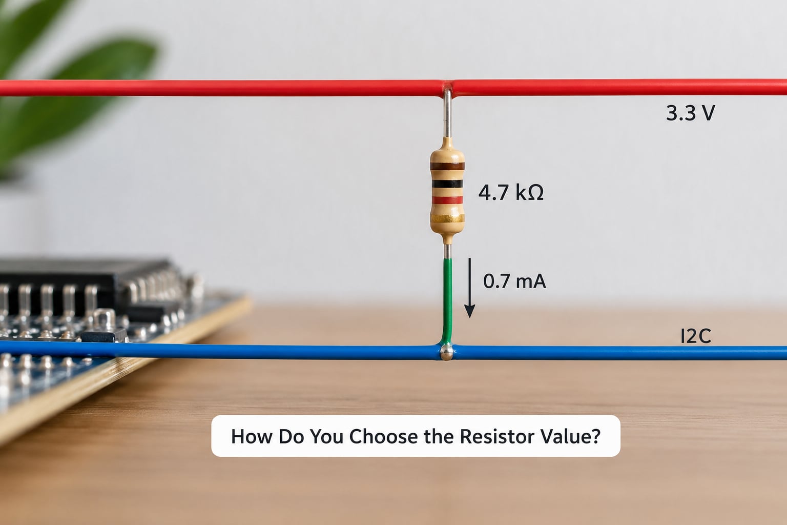
The value is a trade between three things: how much leakage the input can tolerate, how fast the edge has to be, and how much current flows while the line is held against the pull. Lower resistance gives faster edges and better noise immunity but wastes more current. Higher resistance saves current but makes the node slow and vulnerable.
Start with the slowest edge you can tolerate. For an RC-shaped rise, the time to reach the 3.3 V level of a step is roughly 0.69 times the resistance times the total bus capacitance. That gives you the pull resistance for a target rise time. Then check the leakage budget: the drop across the resistor is the input leakage current times the resistance, and it has to stay well inside the input high threshold margin.
That edge-rate habit is the same one that shows up inside the die. Static Timing Analysis Explained for Beginners covers the logic-side version, where a slow RC shape on an output net eats your setup margin. A pull resistor that is too weak creates the same RC shape on a board net, just where you can probe it with a scope instead of a timing report.
Then verify the opposite side. The device holding the line low has to sink VCC divided by the pull resistance. A 4.7 kOhm pull on a 3.3 V bus asks the driver for about 0.7 mA continuously, which is well inside what most I2C sinks can deliver, but a 1 kOhm pull on a 5 V bus asks for 5 mA and many parts will not manage it.
These are starting points, not defaults to copy:
| Application | Starting Point | Watch For |
|---|---|---|
| Standard MCU input, clean board | 10 kOhm pull-up or pull-down | Fine until the enclosure gets noisy |
| Internal MCU bias | 20 kOhm to 50 kOhm | Weak against leakage and long traces |
| I2C at 100 kHz, short bus | 4.7 kOhm | Check the sink current of the slowest device |
| I2C at 400 kHz or a long bus | 2.2 kOhm to 1 kOhm | Total bus capacitance and rise time |
| Low-voltage or battery design | 100 kOhm and up | Leakage dominates, recheck at temperature |
| Long cable or panel-mounted switch | 4.7 kOhm or lower | EMI, and cable capacitance slowing the edge |
| Strap pin | Datasheet value | Sample window and internal pull conflict |
For a low-voltage design, do the leakage math at the highest temperature you will see. Leakage roughly doubles every ten degrees in many parts, so a bias that is comfortable at 25 degrees can fall out of spec in a hot enclosure.
Pull-Up vs Pull-Down Resistor Examples
Example one, an I2C bus. Two sensors and a microcontroller share SDA and SCL at 3.3 V, running at 400 kHz across about 30 cm of track. The pull-up sets the default, so pull-ups go on both lines. Bus capacitance is around 120 pF, and a 2.2 kOhm pull gives a time constant near 264 ns, which keeps the rise inside the fast-mode budget. Each device’s sink current budget and the bus capacitance figure from the datasheet decide the final value. The devices themselves are the components that override the pull-up, by pulling low.
Example two, a reset or enable input. A load switch has an active-high enable driven by a microcontroller GPIO, and the board needs the rail to stay off while the MCU boots. A 10 kOhm pull-down to ground holds EN low until firmware drives it high. Here the GPIO overrides the pull-down. If the switch instead had an active-low enable, the same reasoning flips and you would fit a pull-up.
Example three, an MCU input using its internal bias. A pushbutton connects a pin to ground, and the firmware relies on the internal pull-up so no external component is needed. The internal resistor overrides nothing, it provides the default in the absence of the button. Because the internal value is often 20 kOhm to 50 kOhm, this works on the bench and can misfire near a motor or a long harness, where an external 4.7 kOhm or 10 kOhm pull-up is the better choice.
In all three cases the pattern is identical. Decide the polarity from the datasheet, place the bias so the inactive state is safe, and identify which device is allowed to override it.
Common Problems and Design Mistakes
Connecting a pull resistor to a push-pull output. If a device actively drives high or low while a strong pull opposes it, the two fight and you get excess current into the driver. Push-pull lines need a series termination resistor for edge control, not a pull resistor.
Making the pull too strong. A 1 kOhm pull held low on a 3.3 V line burns about 3.3 mA continuously. On a design that sleeps, that current dominates the power budget. Members of the Arduino and embedded forums regularly find this the cause of a board that will not sleep properly, and the fix is simply a larger resistor. On a bigger board the same arithmetic lands on the supply tree, which is worth reading about in Power Grid Design in Chips Explained: A Beginner’s Guide.
Making the pull too weak. A 1 MOhm pull looks tidy on the schematic and fails next to a switching node. Leakage and induced noise then push the pin out of its valid band. The symptom is intermittent, which is exactly why it eats debugging time.
Biasing a pin twice. An internal pull-up plus an external pull-down on the same pin puts a permanent voltage divider across it, and the pin settles somewhere between the thresholds. Choose one or the other.
Forgetting that a pull resistor does not debounce a switch. A pull sets the resting level and helps noise immunity, but a mechanical contact still bounces for several milliseconds. Add an RC filter or debounce in software.
Skipping the datasheet. Strap pins, I2C devices, and level shifters all come with specified bias values or limits. A community consensus that 10 kOhm is the default for everything is a decent starting thought and a poor excuse.
Common symptoms map back to causes fairly reliably:
| Symptom | Likely Cause | Fix |
|---|---|---|
| Random interrupts or ghost button presses | Floating input, pull missing or too weak | Fit the pull the datasheet calls for |
| Board works on the bench, fails in the enclosure | Weak pull, nearby switching noise | Drop to 4.7 kOhm or lower |
| I2C reads back wrong device address | Rise time too slow, weak pull | Lower the pull value, shorten the bus |
| Rail enables at power-up when it should not | No pull-down on an active-high enable | Add a pull-down to ground |
| Device will not exit reset | Reset held low by noise, no pull-up | Add a pull-up, check trace length |
| Pin stuck at an intermediate voltage | Pull-up and pull-down both fitted | Remove one of them |
| Works at 25 degrees, fails when hot | Leakage through a high-value pull | Lower the value, recheck the leakage budget |
Placement counts as well. Put the pull resistor close to the pin it protects, not at the far end of a long trace. A pull at the driver protects the driver, not the receiver. And if the same trace also leaves the board, remember that cable-borne transient protection is a separate problem, covered in ESD Protection in Chip Design Explained: A Guide.
Which Should You Choose?
Choose a pull-up when the line can be driven low by other devices, which covers I2C, 1-Wire, open-collector interrupt lines, wired-OR alarms, and any part whose reset pin is active low. Choose a pull-down when you want the inactive state to be zero, which covers active-high enables, power-good sequencing, MOSFET gate holds, and buttons that pull to the supply rail.
Existing device requirements beat the general preference every time. If the bus standard or the part datasheet specifies a polarity and a value, that settles the question. What a pull-down can never do on an open-drain bus is create the idle high that the bus depends on, and no pull-up can hold a gate off, because it pulls toward the rail that turns the device on.
Once the polarity is settled, pick the strength from the requirements rather than from habit. Check the input leakage specification, the maximum bus or cable capacitance, the driver’s sink or source current, and the edge rate you need. For most digital inputs on a normal board, 10 kOhm is a sane starting point. For I2C, 4.7 kOhm or lower. For anything crossing a cable, 4.7 kOhm or lower still.
Frequently Asked Questions
Can a pull-up and pull-down resistor be used on the same signal?
Only as a deliberate voltage divider, which is rarely what you want on a logic line. Fitting both puts a permanent divider across the pin, so it settles between the input low and high thresholds and reads undefined. The exceptions are boot strap pins with a weak internal pull and a stronger external one of the opposite polarity, or analogue inputs where a divider is the point.
Why does an I2C bus normally use pull-up resistors instead of pull-down resistors?
Because every device on an I2C bus has an open-drain output. Those devices can pull the line to ground but never drive it high, so something else has to provide the high level. A pull-up to the bus supply does that, and a pull-down cannot, since it would pull every released line to logic low and make every zero ambiguous. The pull-up also limits the current a device sinks while it pulls low.
Is a 10 kOhm pull-up resistor suitable for every digital input?
It is a good starting point for a standard microcontroller input on a short trace in a quiet enclosure, and it is not universal. On a long cable, next to a switching node, or on a line with high input leakage, 10 kOhm may sit too close to the threshold. I2C buses usually need 4.7 kOhm or lower to hit the rise time budget, and high-impedance CMOS inputs may need a much stronger pull.
Do input pins always need an external pull-up or pull-down resistor?
No, not when the device has an internal bias you can enable and the board is electrically quiet. Most microcontrollers offer internal pulls of roughly 20 kOhm to 50 kOhm, which handle a bench prototype or a short button trace. Add an external resistor when the internal one is too weak for the leakage, the noise environment, the cable length, or the edge rate the interface requires.
Why does a pull-up resistor not cause a short circuit when the line is pulled low?
Because the pull resistor carries current rather than bypassing it. With the line held at ground, the circuit is a loop through the resistor, and the current is simply the supply voltage divided by the resistance, about 0.33 mA for a 10 kOhm pull on a 3.3 V rail. That is a small, predictable load. A real short would need the signal wired straight to ground with no resistor in between, which is exactly what the resistor prevents.
Can pull-up or pull-down resistors replace series termination resistors?
No, they solve different problems. A series termination resistor, often 22 to 33 Ohms, sits in line with a fast edge to damp reflections from the line impedance of a long trace. A pull resistor connects to a rail to set a default logic level. Using a pull in place of termination leaves ringing on the edge, and using termination in place of a pull leaves the input floating.
Conclusion
Decide pull up vs pull down resistors explained this way: read the datasheet for the pin’s active polarity, pick the direction that makes the inactive state safe, then size the resistor against leakage, edge rate, and the opposing driver’s current. Start at 10 kOhm for an ordinary digital input, drop to 4.7 kOhm or lower for I2C or anything crossing a cable, and leave internal pulls for bench work.
Do the datasheet check first. It settles the polarity, the value, and the minimum resistance for an I2C sink in one step, and it is the only part of this decision you cannot work out from experience alone.