
Static timing analysis explained for beginners boils down to one idea: a timing tool computes the delay of every path through a digital circuit and checks each one against the clock period you specified, without simulating a single input value. That exhaustive sweep is what makes STA the sign-off check for frequency in any synchronous design.
The idea sounds dry until you see it applied. A path that a functional simulation never exercises can still be 40 ps too slow at the capture flip-flop, and the chip will produce wrong answers on real silicon because the data arrives after the clock edge. STA is the method that finds that path before it costs you a respin.
Below is the mental model first, then the math, then the constraints and reports you will actually look at. Updated for 2026.
Table of Contents
- What Is Static Timing Analysis?
- The four basic principles
- What STA does not check
- How Does Static Timing Analysis Work?
- What Are Timing Paths, Clocks, and Timing Arcs?
- The path types you will see in a report
- Edge and path exceptions
- Setup and Hold Checks: What Are They?
- What Do Slack, Path Groups, and Worst Paths Mean?
- A worked example
- Which Timing Constraints Are Essential for Beginners?
- What Do Common STA Reports and Violations Tell You?
- How Do You Fix Common Static Timing Analysis Failures?
- Start with the constraints
- Then the library and physical side
- Then the logic
- How Can Beginners Run Their First STA Check?
- Frequently Asked Questions
- Is static timing analysis the same as simulation?
- Why does STA report timing violations after functional tests pass?
- What is the difference between max delay and min delay?
- Should a beginner add false paths to make violations disappear?
- What is a fully constrained design?
- Why can fixing setup timing make a hold violation appear?
- Conclusion
What Is Static Timing Analysis?
Static timing analysis is a verification method that checks whether a synchronous digital design can meet its timing requirements, by calculating the delay through every possible path between registers, inputs and outputs, and comparing it to the time the design has available. It reads the netlist, a characterised cell library and a set of constraints, and reports the slack on each path. Nothing is simulated, so no input vector is ever applied.
That distinction matters. Simulation can only ever test the input patterns a testbench feeds it, and a pattern set that misses one path looks exactly as green as one that covers it. STA checks all paths in a single run, which is why it can serve as a sign-off criterion for maximum frequency rather than a smoke test.
The four basic principles
- Everything is a path. STA decomposes the design into startpoint-to-endpoint paths and analyses each one.
- Delay comes from a library, not from guesswork. Cell and net delays come from a Liberty (.lib) file characterised at a specific PVT corner.
- Constraints define correctness. Clock periods, input and output delays and exceptions are your input. Bad constraints produce meaningless results.
- Slack is the verdict. Positive slack passes, zero slack has no margin, negative slack is a violation.
What STA does not check
This is the part most beginner guides leave out, and it causes real damage to a mental model. STA does not check functional correctness; a design can have perfect slack and still compute the wrong result. It does not check functional safety, power or area, and it does not tell you the probability of a metastability event, only whether the circuit was given enough margin for the design intent.
STA and functional simulation are complementary. Simulation answers whether the logic is right; STA answers whether the logic can run fast enough and stable enough to deliver that right answer on hardware.
| Aspect | Static timing analysis | Functional simulation |
|---|---|---|
| Method | Static graph and delay calculation | Applies input vectors over simulated time |
| Coverage | Exhaustive across all paths | Only the stimuli written in the testbench |
| What it proves | Timing requirements are met | Logic computes the intended function |
| Runtime | Minutes to hours, scales with design size | Can be days for long regressions |
| Answers “will it work?” | No, timing only | Partially, for the cases it covers |
How Does Static Timing Analysis Work?
The engine does the same six things every run, whether the tool is PrimeTime, Tempus, an open-source timer or a university lab script.
- Read the netlist. The tool loads the gate-level design, usually after synthesis or place and route, and sees every instance and connection.
- Link the cell libraries. Liberty files for the standard cells are read at one or more PVT corners, giving the tool cell delays, transition times, setup and hold requirements for each flop.
- Build the timing graph. Pins become nodes, nets and timing arcs become edges, and clock definitions determine which arcs are active.
- Propagate arrival times forward. Starting from input ports and launch flops, the tool computes when data can arrive at every pin, using the worst (slowest) cell and net delays for max analysis and the fastest for min analysis.
- Propagate required times backward. From output ports and capture flops, the tool computes the latest time data is allowed to arrive.
- Report slack. Required minus arrival is the slack for that path and corner. Negative slack appears as a violation and updates the worst negative slack and total negative slack summaries.
| Stage | Inputs | Output |
|---|---|---|
| Design read | Gate-level netlist | Connectivity database |
| Library link | Liberty .lib files, PVT corners, parasitics | Per-cell delay and check tables |
| Constraints | SDC: clocks, I/O delays, exceptions | Timing graph with active paths |
| Analysis | Graph plus libraries | Arrival and required times per path |
| Reporting | Slack per path and corner | WNS, TNS, path lists, check_timing report |
What Are Timing Paths, Clocks, and Timing Arcs?
A timing path is a chain that starts where data is launched and ends where it is captured or observed. The launch flop changes state on a clock edge; its output then propagates through combinational logic and must be stable at the capture flop in time for that flop’s next edge.
Two things make this concrete. Clock-to-Q delay is how long after the launch clock edge the launch flop’s output becomes valid. Clock period is the time between consecutive active clock edges, and it is the budget the data path has to fit inside. The launch and capture clock paths are analysed separately, because latency and skew differ between the two flops.
Here is a minimal example. A 2 ns clock drives a launch flop and a capture flop. The launch flop’s clock-to-Q delay is 60 ps, the combinational block between them contributes 1.35 ns including net delay, and the capture flop requires 40 ps of setup time. Total data delay is 1.41 ns against a 2 ns period, so the path has margin to spare before skew and uncertainty are considered.
The path types you will see in a report
- Input to register: an external pin launches data, so it needs an input delay constraint.
- Register to register: the dominant case, and the one that sets your achievable frequency.
- Register to output: needs an output delay constraint.
- Input to output: pure combinational path through the design, checked against a defined requirement.
- Clock gating check: the clock pin of a gated flop must be stable, so the gating logic is timed against the control signal.
Edge and path exceptions
STA also analyses negative-edge (falling-edge triggered) paths, and paths launched on one edge and captured on the opposite edge of the same clock. Those mixed-edge checks are where half-cycle timing bites, and they need explicit multicycle constraints in most designs.
A false path tells the tool two nodes are never connected by a functionally valid timing relationship, so the check is removed entirely. A multicycle path tells the tool a transfer is allowed to take more than one cycle, which relaxes the setup check and usually requires a matching hold exception. Both are legitimate design intent when used carefully, and both are dangerous when used to make a report look clean.
Setup and Hold Checks: What Are They?
Setup time is the window before the active clock edge during which data must already be stable at the capture flop. Hold time is the window after that edge during which data must remain stable. Violate setup and the capture flop may latch the old value or go metastable because the data was still moving. Violate hold and it may latch the new value too early, again with no guarantee.
For a register-to-register path, the setup requirement is:
Data arrival ≤ Clock period + Capture clock skew − Setup requirement − Uncertainty
For hold, the constraint runs the other way. Data must not arrive too early:
Data arrival ≥ Hold requirement + Launch clock skew
Setup slack is then the required time minus the arrival time. Hold slack is the arrival time minus the required hold time. All four values are in the units your constraint file declares, usually nanoseconds.
| Aspect | Setup check | Hold check |
|---|---|---|
| Requirement | Data stable before the capture edge | Data stable after the capture edge |
| Slack formula | Setup slack = Required time – Arrival time | Hold slack = Arrival time – Hold required time |
| Driven by | Clock period and the max path | Shortest path and skew |
| What worsens it | Long wires, big logic depth, slow cells, high fan-out | Over-buffering, short paths, fast cells, positive skew |
| Typical fix | Optimise, resize, buffer, restructure, or speed up the clock tree | Insert delay buffers along the path |
| Analysis library | Slow corner, worst-case | Fast corner, best-case |
Those numbers come from the flop characterisation in the Liberty file for the corner you are running, and the period and skew come from your constraints and clock tree. Different technology, corner and target frequency will give you completely different values, so treat any figure in a tutorial as an illustration rather than a spec.
What Do Slack, Path Groups, and Worst Paths Mean?
Slack is simply how much margin a path has. Positive slack means the data arrived early enough, negative slack means it did not, and a violation is any path with negative slack at any analysed corner.
Two summary numbers appear at the top of every report. WNS, worst negative slack, is the single most negative slack value found, essentially the number that tells you how far from closing you are. TNS, total negative slack, is the sum of all negative slacks, which captures how widespread the problem is. A design with a WNS of 20 ps on one path and a TNS of 2 ns has one bad path. A design with a WNS of 20 ps and a TNS of 300 ns has a systemic problem.
Paths are grouped for reporting, most often by clock pair. A path group is a bucket of paths sharing the same launch and capture clock, such as all paths from clk_core back to clk_core. Groups matter because a report that mixes ten unrelated path groups into one list is much harder to act on than one that ranks the worst group first.
A worked example
Take a 2 ns clock with 40 ps of capture clock skew. The launch flop’s clock-to-Q is 60 ps, the logic plus net delay is 1.45 ns, and the capture flop setup requirement is 40 ps at this corner.
- Data arrival time = 0.06 ns (clock-to-Q) + 1.45 ns (logic and net) = 1.51 ns
- Setup required time = 2.00 ns (period) + 0.04 ns (capture skew) − 0.04 ns (setup) = 2.00 ns
- Setup slack = 2.00 – 1.51 = +0.49 ns. Passes with margin.
- Hold slack on the same path would be computed as arrival minus the hold requirement at the capture flop, and would normally be strongly positive on a long logic path.
That is the whole arithmetic. Reports simply print those numbers per path, and a report line showing arrival 1.51, required 2.00 and slack 0.49 is telling you exactly the calculation above.
One more term you will meet: graph-based analysis propagates delay once across the whole graph, which is fast and conservative. Path-based analysis re-evaluates each path individually and is slower but can show a path that graph-based analysis pessimistically flagged. Most sign-off flows use a mix, with GBA for iteration and PBA on the final paths.
Which Timing Constraints Are Essential for Beginners?
Constraints are where beginners lose confidence, because most tutorials drop them into a command list with no explanation. Every command below is a sentence about your design: this is a clock, this is how long data takes to arrive from outside, these two points never talk to each other.
- create_clock defines a clock: which port, what period, what waveform. Without it, no register-to-register check happens at all.
- Generated clock definitions describe clocks derived from another clock, such as a divided or gated clock, so the tool knows the relationship.
- set_input_delay says how much of the cycle is already spent before data arrives at an input port, from the outside world or from launching logic outside the block.
- set_output_delay says how much time the outside world needs after your output leaves.
- Clock groups and asynchronous clock groups mark clocks that have no timing relationship, which cuts checks between them.
- Case analysis fixes a control input to a constant so the tool can prune unreachable logic.
- set_false_path and set_multicycle_path are exceptions that remove or relax checks where the design genuinely permits it.
| Constraint | What it expresses | Symptom if missing |
|---|---|---|
| create_clock | Clock period and waveform | No register-to-register paths reported |
| Input delay | External arrival time relative to clock | Unconstrained input-to-register paths |
| Output delay | External requirement after the register | Register-to-output paths left unchecked |
| Generated clock | Relationship to a parent clock | Wrong checks on divided or gated clocks |
| Asynchronous clock groups | No relationship between domains | Spurious violations across unrelated domains |
| False or multicycle path | Deliberate exception | Either real violations ignored, or noise |
The rule I would give anyone new: a constraint is real design intent or it is a bug. Before writing a false path, confirm the transfer genuinely cannot happen, in functional mode and in every test and debug mode. Before writing a multicycle path, remember it loosens setup and tightens hold in the opposite direction, so it usually needs a matching hold exception.
What Do Common STA Reports and Violations Tell You?
A report is a diagnosis, not just a score. Most violations fall into a handful of recognisable categories, and each one points at a specific piece of missing or wrong information.
Unconstrained endpoints or unconstrained paths. The tool found registers it cannot time because no clock, input delay or output delay reaches them. Fix the constraints before touching the design.
Setup violations. The data path is too long for the period. Usual causes are excessive logic depth, a long unbuffered net, a slow cell chosen by synthesis, a high-fan-out net, or pessimistic constraints such as excessive uncertainty or a wrong corner.
Hold violations. Data arrived too early. Common causes are over-buffering done during setup optimisation, a short path, positive clock skew, or a hold fix applied on one path that broke a neighbouring one.
Clock domain issues. Violations between clocks that were never meant to be related, or missing generated clock definitions producing odd periods. These usually point at asynchronous grouping or derived clock constraints.
Blank or zero setup and hold values. Beginners often see a report with no setup time, no hold time and no slack shown at all. In most cases that is a constraints or timing graph problem rather than a sign-off verdict, and the check_timing summary is where you confirm it.
Whichever category you land in, collect the same evidence before changing anything: the full path detail, the startpoint and endpoint, the launching and capturing clock, the corner, the clock path insert and skew values, the data path delays cell by cell, and the constraint that governed the path. Without those, you are guessing.
One expectation to set early. Running STA straight after synthesis usually shows negative slack, and letting placement and routing recover most of it is normal. Pre-layout numbers are pessimistic because there are no real wire delays yet, so a post-synthesis report is a directional signal, not a verdict.
How Do You Fix Common Static Timing Analysis Failures?
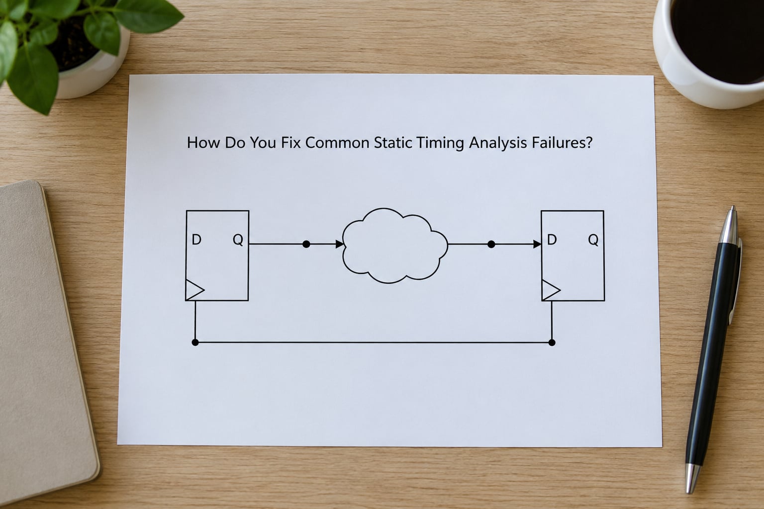
Work the failures in a fixed order, cheapest cause first. Rushing to logic restructuring when the real problem is a missing input delay wastes days.
Start with the constraints
Check for unconstrained paths and confirm the clock definition matches the real frequency. Verify the input and output delays reflect the actual external interface, and review every false path and multicycle path with the design owner. More “impossible” violations than anyone can account for is a strong signal that an exception has hidden a real path.
Then the library and physical side
Long or slow data paths are fixed with buffering and load buffers on high fan-out nets, cell upsizing for drive, cloning for delay, and placement changes that shorten the route. Setup violations also improve with a faster or better-balanced clock tree, since a positive skew into the capture flop effectively buys you time. Hold violations go the other way: insert delay buffers on the short path, or adjust skew deliberately.
Then the logic
When structure is the cause, you are looking at combinational depth. Push a pipeline stage in, restructure the boolean logic, balance the branches so no single path is much longer than the others, or move arithmetic into a dedicated macro with its own timing. This is the expensive option because it means another round of synthesis, so exhaust the physical options first.
After any fix, re-run the whole analysis, not just the path you changed. Adding delay to fix hold on one path lengthens nothing, but a setup fix that inserts a buffer in a shared net can easily create a new hold violation somewhere else.
How Can Beginners Run Their First STA Check?
You do not need a commercial licence to learn this. The flow is identical in shape whichever tool you use; only the menu names and command syntax differ across PrimeTime, Tempus, other commercial tools and the open-source flow.
- Start small. Pick a handful of flip-flops with one clock and a short combinational path. A 20-cell design teaches the same concepts as a two-million-cell one.
- Get libraries and constraints. You need a Liberty file matching your cells, one slow corner and one fast corner, a SPEF or extracted parasitics file if you are post-layout, and an SDC that defines the clock and your I/O delays.
- Run the check. Ask for the worst setup path and the worst hold path by slack, and set reporting to show full path detail rather than a summary only.
- Read one line end to end. Identify startpoint, endpoint, clock, arrival time, required time, slack, and the cell-by-cell breakdown. Repeat until the line makes sense to you without help.
- Break it on purpose. Add a long combinational chain, re-run, and watch slack go negative. Then insert a pipeline register and watch it recover. Nothing teaches the model faster.
- Write a one-page review note. The path, the corner, the cause, the fix and the re-run result. Sign-off discipline is the habit worth building, not the tool.
For the open-source route, Yosys and OpenROAD produce a netlist and a placed design that OpenSTA can time, which means you can reproduce every example in this article at home. When you move to a commercial tool later, the concepts transfer directly even though the syntax does not.
Frequently Asked Questions
Is static timing analysis the same as simulation?
No. Simulation applies input vectors and watches the outputs change, so it only proves the cases your testbench actually exercises. Static timing analysis applies no vectors at all: it calculates the delay through every path and compares it against your clock and interface constraints. Simulation tells you whether the logic is correct, STA tells you whether it can run fast and stable enough to deliver that answer on hardware.
Why does STA report timing violations after functional tests pass?
Because the two checks answer different questions. Passing functional tests says the design computes the right answer for the patterns you simulated, and says nothing about the speed of paths those patterns never touched. A path that is too slow at the capture flop will still fail on silicon, and STA is the only check that looks at every path exhaustively rather than only the stimulated ones.
What is the difference between max delay and min delay?
Max delay analysis uses the slow corner of the library and the longest path through the circuit, and it is what the setup check cares about. Min delay analysis uses the fast corner and the shortest path, and it is what the hold check cares about. In short, max delay answers can the data arrive in time, and min delay answers is the data arriving so fast that it overshoots the capture flop’s hold window.
Should a beginner add false paths to make violations disappear?
Only when you can state the design intent behind the exception. A false path is a claim that data never travels between those two points, so using one to silence a real violation hides a genuine bug rather than fixing it. This guide to static timing analysis explained for beginners is deliberately blunt about it: fix constraints first, fix the physical path second, and only add exceptions that a design owner has confirmed are real.
What is a fully constrained design?
A design where every timing path in the graph is either checked or deliberately excluded by a stated exception. In practice that means every clock is defined, every input and output port has a delay, derived clocks are described, and asynchronous domains are grouped. The check_timing summary in your tool reports unconstrained paths, and an empty unconstrained section is the clearest signal that your constraints are complete.
Why can fixing setup timing make a hold violation appear?
Setup fixes usually involve optimising the longest paths, which often means removing delay or inserting a buffer in a shared location. Hold depends on the shortest paths in the design, so any change that speeds up a short path, or that shifts clock skew between the launch and capture flops, can push a path below the hold requirement. Fix setup, re-run the full analysis, then work the hold violations that surface.
Conclusion
Static timing analysis is arithmetic on delay, applied to every path in a design, judged by slack. For a beginner, the order of operations matters more than any tool: learn launch and capture registers and the two checks, write accurate clock and I/O constraints, read the worst path line by line, fix the cause rather than the symptom, and re-run the whole analysis after every change. Keep exceptions to genuine design intent, and the numbers will tell you the truth.