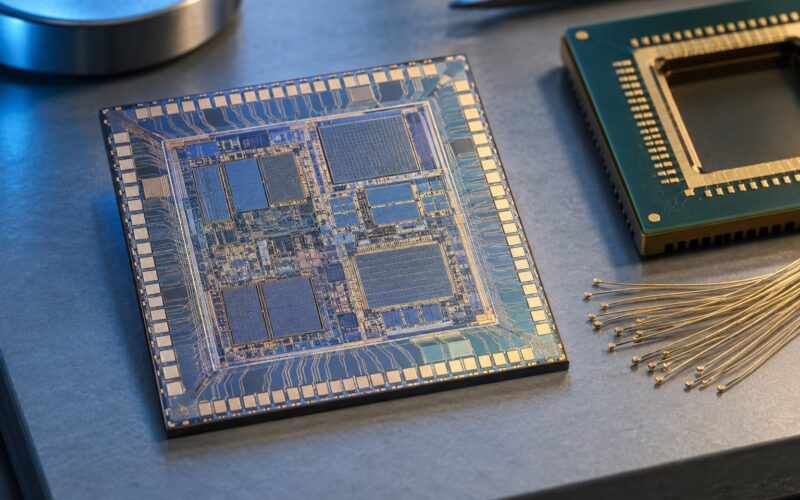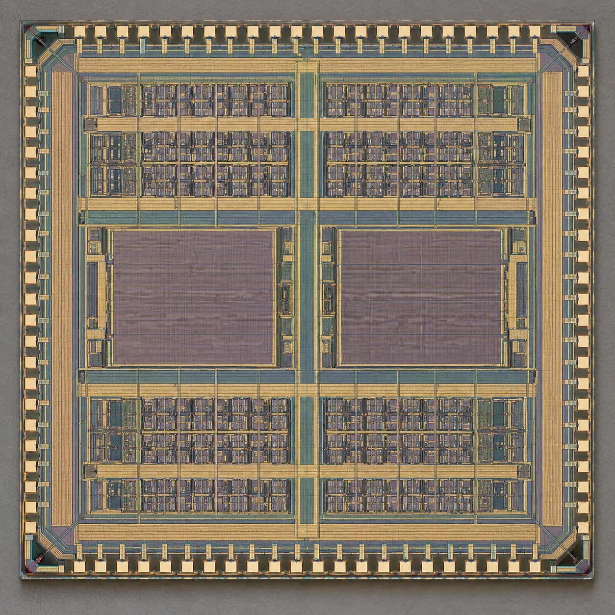
Place and route is the physical implementation stage of ASIC design: it takes a synthesised gate-level netlist and turns it into a chip layout, placing every standard cell and memory macro on the die and drawing the metal layers and vias that connect them. The flow runs in a fixed order — floorplan, power planning, placement, clock tree synthesis, routing, optimisation, sign-off — and it loops, because each stage’s results feed the next and send problems back upstream.
Most beginners meet the flow as a wall of unfamiliar names. Innovus, IC Compiler II and OpenROAD all label their phases differently, and the textbook vocabulary assumes you already know what a g-cell or a routing bin is. This guide takes the flow apart stage by stage, states what goes in and what comes out of each stage, and names the checks that decide whether a layout is ready to leave the building.
Updated for 2026.
Table of Contents
- What Is a Place and Route Flow?
- Where the Place and Route Flow Starts
- What Inputs Does the Place and Route Flow Need?
- How Does Floorplanning Shape the Layout?
- What Happens During Placement?
- How Does Routing Connect the Design?
- How Are Timing, Power, and Area Optimized?
- What Checks Happen Before Final Signoff?
- Frequently Asked Questions
- What is the difference between placement and routing in EDA?
- Can place and route tools fix timing problems in RTL?
- Why does an IC design become unroutable after placement?
- What is the role of SDC constraints in place and route?
- What deliverables are required before sending a layout for signoff?
- Conclusion: What to Check First
What Is a Place and Route Flow?
Place and route (PnR, also called APR for automated place and route) is the back-end stage of the design flow where an abstract circuit becomes geometry. Synthesis hands over a list of cells and the wires between them. Place and route decides where each cell physically sits and how each wire physically runs, using real metal widths, real track pitches and real layer counts from a foundry process.
The distinction that trips up almost every newcomer is that P&R is neither logic nor verification. It cannot invent a better algorithm, and it cannot prove the design works. It answers a different question: can this circuit physically exist at the target frequency, area and power, and can a foundry manufacture it without errors.
That is also why P&R sits in a specific place on the clock. It runs after signoff-verified RTL, runs alongside verification, and ends with a GDSII stream-out that goes to the mask shop. A clean P&R result with timing closed and design rule checking clean is the precondition for tapeout. A netlist with no layout is not a chip.
The ordered flow, in the order stages normally run:
- Data setup and floorplanning — load the netlist and libraries, size the die, place the hard macros.
- Power planning — build the power ring, power straps and power distribution network.
- Placement — position every standard cell into legal rows and legalise the result.
- Clock tree synthesis (CTS) — build the clock network, balance skew and insertion delay.
- Routing — global route, assign tracks, then detail route with metal and vias.
- Post-route optimisation — fix residual timing, congestion and design rule violations.
- Sign-off — timing, DRC, LVS, EM, IR drop, antenna, then stream out.
Each stage produces a database plus reports, and each stage has its own exit criteria. Here is the handoff map most teams work against:
| Stage | Primary inputs | Key outputs | Exit check |
|---|---|---|---|
| Data setup | Netlist, LEF, LIB, SDC, UPF, blockages | Initialised database, floorplan file | Libraries linked, no unresolved cells |
| Floorplan | Die size, macro list, pin constraints | Core area, macro and pin locations, utilisation report | Aspect ratio and density are sane, macros have channels |
| Power planning | Floorplan, power budget | Power ring, straps, tap cells, IR-drop target | IR drop within budget at the centre of the core |
| Placement | Floorplan, netlist, timing data | Legalised cell database, placed DEF, clock tree | Zero placement DRC, timing and density at target |
| Routing | Placed database, routing layers | Routed DEF, routed SPEF, via counts | Routing DRC and antenna clean, hold clean |
| Optimisation | Routed database, ECO requests | Repaired routes, sizing and buffering changes | Setup and hold slack met at all corners |
| Sign-off | Final database, foundry rule decks | GDSII/OASIS, reports, LVS and EM sign-off | Zero DRC, LVS match, EM and IR clean |
Note the shape of that table. Nothing downstream is more accurate than what it inherited, which is why input discipline matters more than tool choice. One stale Liberty corner or one missing placement blockage will surface as a timing problem four stages later, and it will get fixed in the wrong place by people chasing the wrong symptom.
Where the Place and Route Flow Starts
The flow starts before any tool command runs, with an input review. The synthesised gate-level netlist arrives with a constraints file and a set of physical and timing targets, and the physical design engineer checks that all of them agree with each other before loading anything.
On the library side you need the standard-cell and macro views for the exact corner being implemented. On the constraint side you need the clock definitions, the I/O delays, the false and multicycle paths, the drive and load settings, and the modes and corners the design must close in. On the planning side you need a die size, a macro list, an IO pin budget, and any keepouts the DFT or low-power team requires.
Tool selection is usually inherited rather than chosen. Most production ASIC work runs on Cadence Innovus or Synopsys IC Compiler II, with PrimeTime for sign-off timing. OpenROAD has become a credible option for smaller designs and for academic and research flows, and it is useful to know because its phase names are becoming common vocabulary. What matters more than the brand is that the methodology matches the design: which corners are setup-critical, which are hold-critical, what the congestion target is, and how many iterations the schedule can absorb.
What Inputs Does the Place and Route Flow Need?
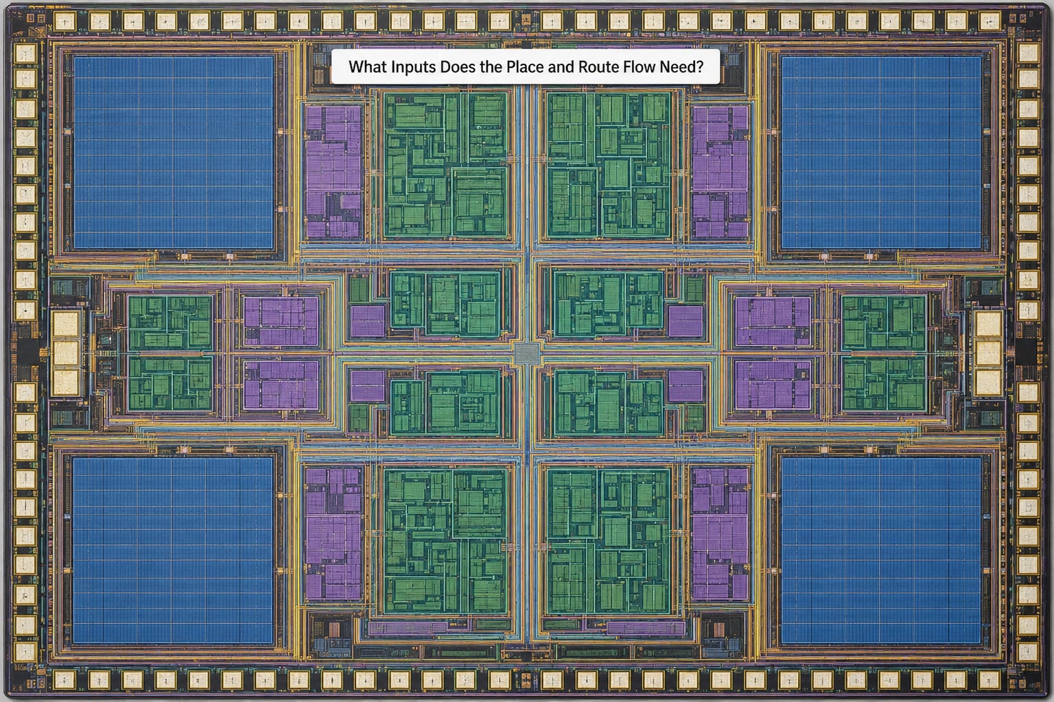
Nearly every bad back-end week traces back to one of the files below. Knowing which symptom maps to which input saves the hours you would otherwise spend experimenting with tool settings that were never the problem.
| Input | Owner | What it contains | Symptom when it is wrong |
|---|---|---|---|
| Gate-level netlist | Synthesis | Instantiated cells, connectivity, hierarchy | Unplaceable cells, unresolved references, wrong drive strength |
| Liberty (.lib) | Library / foundry | Timing arcs, capacitance, transition limits, leakage | Timing that never closes no matter what the tool does |
| LEF (.lef) | Library / foundry | Cell abstracts: footprint, pin geometry, obstruction | DRC errors on pins, routing that cannot legally reach a port |
| SDC (.sdc) | Front-end / constraints | Clock periods, I/O delays, exceptions, uncertainty | Implausible slack, hold failures everywhere, CTS optimising nothing |
| UPF (.upf) | Low power | Power domains, isolation and level-shifter rules | Wrong cells inserted, power-up sequence DRC failures |
| Floorplan file | Physical design | Die boundary, core area, macro and pin locations | Congestion, unrouteable channels, blown die area |
| Placement blockages | DFT / integration | Reserved regions for scan, analog, integration | Late congestion, last-minute macro moves that wreck timing |
| Foundry rule deck | Foundry | DRC, LVS, EM and antenna rules per layer | Sign-off failures that cannot be fixed without a respin |
One more input that is easy to forget and expensive to omit: the parasitic view. Early placement uses a wire load model, which is a statistical guess. From around mid-place onward the tool should be using real extracted resistance and capacitance, otherwise the tool is balancing against numbers that will be thrown away at sign-off.
How Does Floorplanning Shape the Layout?
Floorplanning is where the physical constraints of the process meet the logical demands of the design, and it is the stage with the most downstream leverage. Almost every later problem — congestion, unrouteable channels, IR drop hotspots, routing detours that kill setup slack — starts as a floorplan decision.
Three quantities drive the sizing work. Chip-level utilisation is the standard-cell area divided by die area. Floorplan utilisation is the area available for placement, which is the core minus macros, the power ring, the pad ring and any reserved blockages, divided by core area. Row utilisation is what the standard cells actually consume inside a standard-cell row, once fillers and power stripes are accounted for. When a design is at 90% row utilisation, the tool has no room to legalise, and every timing fix that wants to swap in a bigger cell fails.
Aspect ratio is the other lever. A very tall, narrow die is cheap to build but routes badly at the corners and suffers from clock skew across a long distance. Most teams target something close to square, and the long edge is where macros with a lot of pins get placed so their escape routes have room.
Macro placement sets the congestion map for the whole run. Two macros side by side with a channel between them create a pin-versus-track imbalance, and no amount of routing effort fixes it — the flylines simply have nowhere to go. The fix is pre-placement: widen the channel, rotate the macro to spread its pins, or insert a placement blockage that forces the tool to route around with a higher layer rather than through a pin-short gap. This is the single most common full-chip congestion failure, and it is exactly the kind of question physical design interview lists keep asking about.
Pin placement and IO assignment come from the integration side, usually the system architect. Ports on the same side of a block should land near each other on the die, and high-fanout signals need short, direct routes from their source. Power planning follows immediately: a power ring around the core plus wide parallel straps carrying power inward, sized from the power budget using simple voltage-times-current arithmetic. Strap width scales with how much current each strap carries and how long it runs, and the tap cells that bond the substrate must be distributed through the core rather than clustered at the edges.
What Happens During Placement?
Placement answers one question: where does each standard cell go? It is done in two clearly different halves, and knowing which is which clears up most of the terminology confusion.
Global placement runs first and it is deliberately illegal. Cells are spread over a continuous region using analytic or quadratic placement methods, weighted by timing criticality, net length, congestion estimates and density targets. Cells overlap freely at this stage. The output is a rough ordering and a rough geography — logic in the right neighbourhood, the datapath cells clustered where they talk to each other, the memory macros surrounded by their users.
Detailed placement then makes that result physical. Legalisation removes every overlap and snaps each cell into a standard-cell row without breaking design rules or destroying the timing gain global placement found. Cells that still overlap after row assignment are spread, swapped or resized. A small fraction of cells that cannot be resolved locally get re-placed, which is why a run’s placement phase can feel slow even when the server count is high: the hard cases are inherently local and sequential.
Three things happen inside that phase that are worth naming. High-fanout nets get buffered and spread, because a signal driving four hundred sinks is a transition-time and max-cap problem as much as a routing problem. Density is enforced, so the tool inserts placement blockages in congested regions to stop it from filling every gap with cells. And timing-driven placement uses the extracted parasitics to keep launch and capture registers close together on critical paths, which is worth far more than any later gate sizing.
Clock tree synthesis sits inside or immediately after placement, and that position is not arbitrary. The clock buffer tree is itself a placed and routed structure, so it has to exist before the signal routes are finalised. CTS balances insertion delay and skew, and it is where useful skew is decided: a small amount of deliberate skew on a non-critical path buys slack on a critical one. Hold violations then get fixed after CTS rather than before, because moving a register or a clock buffer after the tree is built costs more than it gains.
How Does Routing Connect the Design?
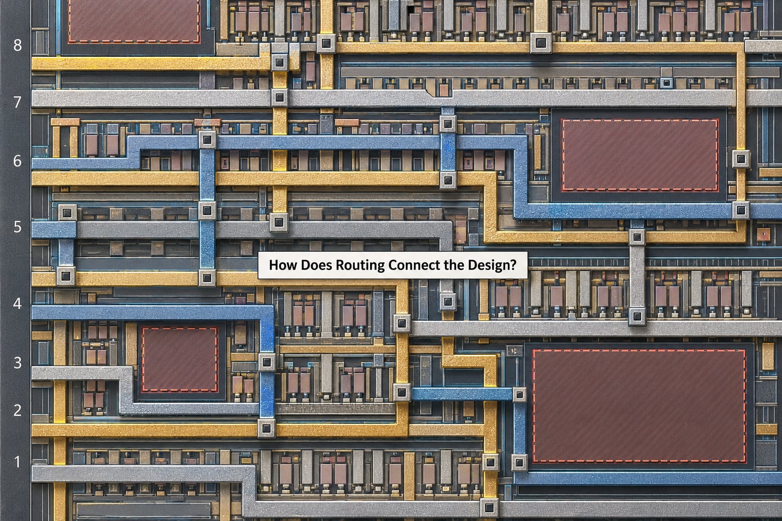
Routing turns a placed database into a connected one. It runs in three sub-stages, and the sub-stages exist because a full-chip router cannot reasonably search billions of candidate paths all at once.
- Global route — The design is divided into g-cells, and the router decides which layer each net uses to cross each g-cell boundary. It builds a routing graph of guide paths, assigns a track capacity estimate to every g-cell, and reports congestion where demand exceeds capacity.
- Track assignment — Each net is given specific tracks and layers inside the g-cells it crosses, reserving the exact resources the detailed router will need. Getting this wrong is how a design fails with a short or an open at the end.
- Detailed route — The router draws actual metal shapes and vias, respecting spacing, width, extension and via-count rules. Signal repair then fixes opens, shorts and DRC hits left behind.
Global routing is a capacity problem, detailed routing is a geometry problem. That framing explains most routing failures: too many nets crossing one g-cell is a global-route congestion issue, while a via array that violates spacing is a detailed-route DRC issue with a different fix.
Modern designs are searched in multiple modes. Early routing uses a small library of wide, low-layer-count shapes to get connectivity fast, then a mid route expands the search, and the final route uses the full library with signal shielding, via redundancy and antenna-fixing jumps. Antenna violations happen when a long metal segment accumulates charge with no diode to discharge it, and the fix is either a metal jumper to a diode-connected cell or a shorter route.
How Are Timing, Power, and Area Optimized?
The flow closes timing by iterating, not by running once. Placement optimises against estimated parasitics, routing produces real ones, and the difference between the two usually costs slack. The loop is: extract, measure, repair, re-route, measure again.
Setup and hold are fixed in opposite directions, and confusing them wastes iterations. A setup violation means the data arrives too late — the path is too long or the launch clock too early. Fixes are downsizing to reduce capacitance, buffering a long net, moving cells closer, using a higher metal layer, or applying useful skew. A hold violation means the data arrives too early — the path is too short. Fixes go the other way: insert delay buffers, downsize the driving cell, pull the capture clock earlier, or place a delay cell deliberately.
Other violations have their own remedies. A max-cap violation means a net drives more load than the cell’s output can handle, fixed by splitting the net with buffers. A transition violation means a slew rate is outside the library limit, fixed by upsizing the driver. Neither is fixed by moving cells, and doing that anyway is a common waste of a day.
Congestion and DRC recovery is its own discipline. When the router reports open or short violations, the causes are usually upstream: macros too close together, utilisation too high, blockages missing, or a netlist with far more connectivity than the layer count can carry. Post-route ECOs — buffer insertion, gate swapping, double-via insertion, spare cell filling — handle the residue. Spare cells are inserted during placement precisely so these fixes have somewhere to go; a design with no spare cells cannot be repaired without a full re-route.
Power optimisation runs alongside all of it: clock gating to stop the clock on inactive blocks, high-fanout net buffering with low-drive cells, multi-voltage domains to keep unused logic off a higher supply, and downsizing where timing allows. The tradeoffs are real and constant. Bigger cells buy slack and cost area and leakage. Tighter spacing buys area and costs routability and IR drop. Useful skew buys setup and costs hold margin elsewhere.
What Checks Happen Before Final Signoff?
Sign-off is a checklist, not a stage you can partially pass. Each check has a named tool, a named rule deck and a named failure mode.
Timing sign-off runs in PrimeTime against extracted SPEF parasitics at every setup and hold corner, with real clock uncertainty and real OCV derates. Setup timing is checked with the clock tree fully routed; hold is checked with the minimum path. A design that passes at zero corners is not closed.
Design rule checking covers geometry: metal width and spacing, via arrays and via enclosures, end-cap and well-tap rules, density rules for fill and metal, and the antenna rules. DRC must be zero, not “mostly clean” — the foundry checks every violation.
LVS compares the final layout against the netlist and confirms that what was built is what was designed. It is the last line of defence against a mis-sized cell or a wrong connection, and a mismatch here is a respin, not a patch.
Electromigration and IR drop check that current density in every metal and via does not exceed reliability limits, and that voltage drop across the power grid stays inside budget at the worst point — usually the centre of the core during peak current draw. An IR drop hotspot that appears only at sign-off normally traces back to power planning at the start of the flow.
Signal integrity and antenna checks cover crosstalk on coupled nets, pushers and receivers, and the antenna ratio rules already mentioned. Connectivity checks confirm every net is fully connected with no dangling pins. Formal equivalence confirms the routed layout is functionally the same netlist you started with.
Deliverables at hand-off are the final GDSII or OASIS database, the DRC and LVS clean reports, the EM and IR sign-off reports, the timing reports, the parasitic extraction files, and a fill file for metal density. That package goes to the foundry, and from that point the design is frozen.
Frequently Asked Questions
What is the difference between placement and routing in EDA?
Placement decides where each standard cell and macro physically sits on the die, inside standard-cell rows and without overlaps. Routing then draws the metal layers and vias that connect those placed cells, obeying spacing, width and layer-assignment rules. Placement is a geometry and timing problem; routing is a capacity and geometry problem. Both iterate together, because a legal placement can still be unroutable.
Can place and route tools fix timing problems in RTL?
Only partially, and only if the RTL left the headroom. Place and route can buffer, resize cells, move logic closer together, use higher metal layers and apply useful skew, which recovers a lot of delay. It cannot restructure a badly pipelined datapath, remove a combinational loop, or fix a path with no logic-depth headroom. If a path fails by a large margin at zero wire load, the fix belongs upstream in RTL.
Why does an IC design become unroutable after placement?
Usually the floorplan, not the placement algorithm. Two macros placed too close together create a channel whose pin demand exceeds its track capacity, and no routing effort fixes it. Other causes are high utilisation leaving no room for legalisation, missing placement blockages, a power grid consuming routing resources, or a netlist whose connectivity exceeds what the layer count can carry. The fix is almost always a pre-placement change.
What is the role of SDC constraints in place and route?
The SDC file tells the implementation tools what the design must achieve: clock periods and uncertainty, input and output delays, exceptions such as false and multicycle paths, and which corners matter. Placement and clock tree synthesis read it to decide what to optimise. An incomplete or stale SDC produces slack numbers nobody believes and an optimiser that works on the wrong paths, so constraint sign-off happens before implementation, not alongside it.
What deliverables are required before sending a layout for signoff?
A frozen database plus the reports that prove it. In practice: the final GDSII or OASIS layout with its fill file, a zero-violation DRC report, a clean LVS result, EM and IR drop sign-off reports, setup and hold timing reports across all corners, and the parasitic extraction files. Sign-off means a third party can reproduce your conclusions from those files. A database without the reports is just a drawing.
Conclusion: What to Check First
Start at the top of the place and route flow, not the bottom of a log file. Confirm the netlist is complete and the cell set matches the library, confirm the constraints are realistic and current, confirm the floorplan has routable channels and power headroom, and confirm every technology file is the version you think it is. Get those four right and the rest of the flow becomes a series of engineering problems rather than a search for the mistake you made in week one.