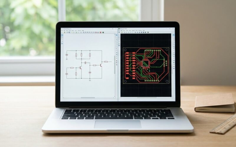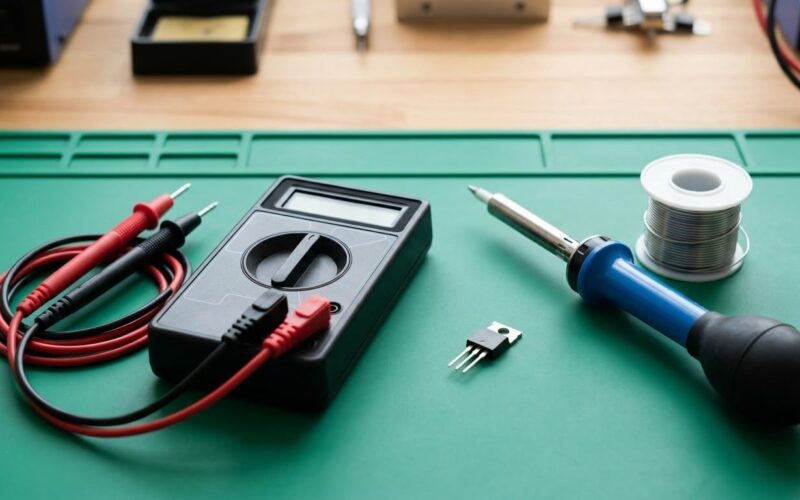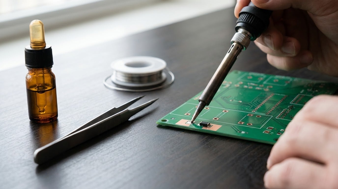
Yes, you can hand solder SMD components. Almost every prototype build, every rework session and every field repair on a populated board gets done with an iron, a spool of solder, a flux pen and a pair of fine tweezers — no pick-and-place machine or reflow oven involved. Surface mount devices sit on flat pads rather than poking through holes, so the whole job comes down to heating one pad, dropping the part into the molten solder and letting surface tension align it.
The catch is precision. A joint you can see on a 1.6 mm through-hole pad becomes a hairline target when you drop to 0402, and heat that would be gentle on a large pad will scorch a tiny one in seconds. Give yourself an afternoon on a scrap board, start at 0805 and step down in size as your hands get steadier.
The golden rule, the one that fixes most beginner problems: heat the joint and let the solder melt into it. Never melt a bead on the iron tip and smear it onto the pad — that is what produces cold joints, solder balls and bridges.
Table of Contents
- What You Need to Solder SMD Components by Hand
- Package Size to Method: Which Technique Applies
- Step by Step
- How to Solder SMD Components by Hand: Prepare the PCB
- Choose the Correct Iron Temperature and Tip
- Solder the First Pad and Hold the Part
- Solder the Remaining Pads
- Inspect, Cool, and Clean the Joints
- Common Mistakes
- Frequently Asked Questions
- Can you hand solder SMD components?
- What is the golden rule of soldering?
- What temperature should my soldering iron be for SMD?
- What solder should I use for hand soldering SMD, leaded or lead-free?
- Can I solder SMD components with hot air instead?
- How do I remove an SMD component and do I need flux?
- Conclusion
What You Need to Solder SMD Components by Hand
The equipment list is short, and the specs matter more than the brand. Anyone can learn how to solder SMD components by hand, but the iron has to put heat into a small joint fast and then get out of the way.
- Temperature-controlled soldering iron with a digital readout. Set it to 300-330 °C for leaded solder on ordinary two-layer boards.
- Fine tip, 0.2 mm to 0.5 mm. A 1 mm chisel that works fine on a through-hole board will physically not fit between two 0.5 mm pads.
- Rosin-core solder wire, 0.3 mm to 0.5 mm diameter, with flux in the core. Thinner wire means less solder per joint, which is exactly what small pads need.
- Flux. A liquid flux pen or syringe for fine-pitch work, or just the rosin core in the wire for simple two-pad parts.
- ESD-safe fine-point tweezers — straight, reverse-action or angled. Brass or steel, pointed tips that will not scratch a pad mask.
- Isopropyl alcohol (90% or higher), cotton swabs and a stiff brush for cleaning pads before and after.
- Brass wool and a tip cleaner for re-tinning a tip that has oxidised.
- Magnification — a loupe, a jeweller’s loupe on a stand, or a USB microscope clamped to a stand. You need at least 5x to inspect an 0603 joint properly.
- Fume extraction and safety glasses. Flux smoke and molten splatter are the two things that actually hurt people at this hobby.
Optional, and worth adding later: a hot-air rework station for removal and QFN work, solder wick and a solder sucker for desoldering, and a stencil plus solder paste if you ever assemble a board with more than a handful of parts on it.
There is one more thing nobody buys and everybody needs: a scrap PCB with a few pads on it. Practice parts get destroyed. That is the point.
Package Size to Method: Which Technique Applies
Beginners get stuck because nobody tells them which technique suits which part. This table is the whole decision in one place.
| Package | Lead pitch | Difficulty | Recommended method |
|---|---|---|---|
| 1206 / 0805 resistors and capacitors | N/A (two pads) | Easy | One-pad anchor with an iron. Where every beginner should start. |
| 0603 | N/A (two pads) | Moderate | One-pad anchor, finer tip, flux. Needs magnification to see what you are doing. |
| 0402 | N/A (two pads) | Hard | Flux pre-tinning plus one-pad anchor. Retouching with the tip is normal. |
| 0201 | N/A (two pads) | Very hard | Only with a microscope and flux. Paste-and-oven beats hand soldering at this size. |
| 5050 LEDs (WS2812 and similar) | N/A (four pads) | Easy to moderate | Solder opposite corners first to lock it, then fill the other two. |
| SOIC / TSSOP (0.5-0.65 mm) | 0.5-0.65 mm | Moderate | Anchor one pin, then solder pin by pin with a fine tip. |
| QFP / TQFP (0.5-0.8 mm) | 0.5-0.8 mm | Hard | Drag solder one side at a time, or use solder paste and a hot plate. |
| QFN / LQFN (pads underneath) | 0.4-0.65 mm | Hard | Pre-tin both rows, seat on melt, tack opposite corners, test with a multimeter. |
The honest dividing line is 0603. Below that you are not really soldering so much as melting metal in a space smaller than a grain of rice, and you are guessing unless a microscope shows you what the iron is doing.
Step by Step
How to Solder SMD Components by Hand: Prepare the PCB
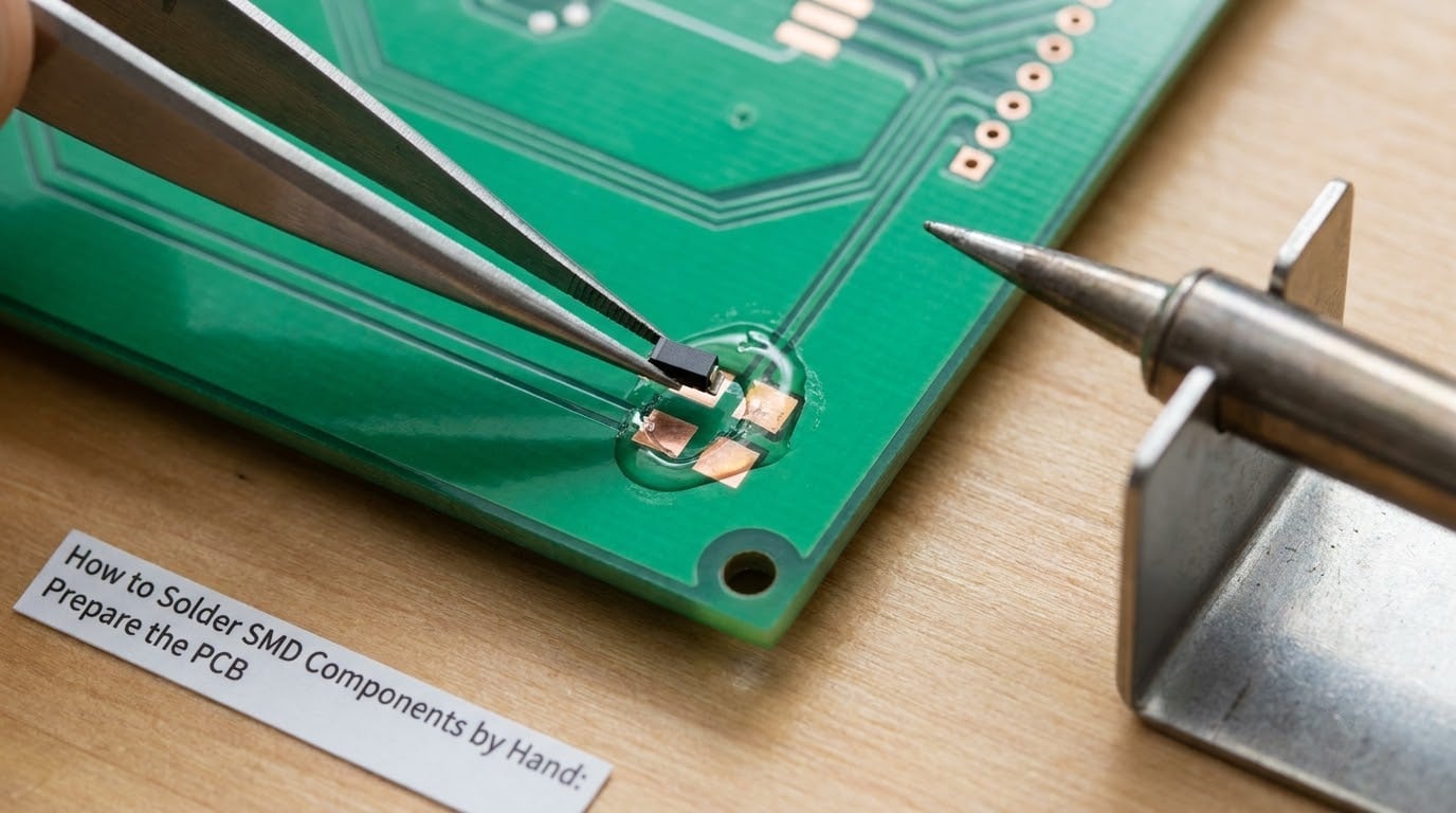
Start with a board that is already clean. If the pads are greasy or have oxidation on them, isopropyl alcohol on a cotton swab and a light scrub fixes it — solder will not wet a surface that is not clean, and you will misdiagnose the problem as bad heat.
Find your pads using the silkscreen outline. Every board prints a white outline of the part body right next to the pads. Before you heat anything, lay the component on the outline so the pads align with the outline centre. If a pad looks torn or has a dark ring around it, that pad was lifted at some earlier point in the board’s life and you should expect trouble.
Work out which way the part faces. A diode or polarised capacitor has a stripe or a dot. Get it backwards and the part will not work no matter how good your joint is.
Put a small amount of flux on the pads before you place the part. The flux removes the oxide film on the copper and lets molten solder spread into a smooth fillet instead of sitting on top as a ball. You are finished when you can see a faint clear or amber film, not a white paste blob.
Choose the Correct Iron Temperature and Tip
Start at 320 °C with leaded solder and 350 °C with lead-free. Push to 380 °C only if the joint refuses to flow on a large ground pad, and drop to 300 °C if nearby parts discolour or the pad starts to lift.
Temperature is a compromise between too low, where the solder melts but the pad and lead never reach liquidus and the joint stays cold, and too high, where flux burns off before it can do its job and the trace or pad underneath darkens. Most “my solder won’t stick” complaints are actually a cold joint from an underpowered iron, not a dirty pad.
For 0805 and 1205 parts a 1 mm chisel works. From 0603 down use a 0.5 mm chisel or a 0.3-0.5 mm conical tip, which fits a single pad without touching its neighbour. For drag soldering an SOIC, TSSOP or QFP, a bevelled or knife tip around 1-1.5 mm is what carries a bead of solder along a whole row of pins.
Tin the tip before every job. Heat it, feed a little solder on, and wipe it on brass wool so it is coated in a bright bead of silver rather than a crust of grey oxide. An oxidised tip has no heat transfer to the joint — the solder sits on the iron and refuses to go anywhere.
Solder the First Pad and Hold the Part
This is the one technique that most beginners are missing, and the one that shows up again and again as the top answer on soldering forums: solder one pad first, then drop the part into the solder.
Hold the solder in one hand and the tweezers in the other, with the iron already resting on its stand. Touch the iron to one pad, wait a beat, then feed a small amount of solder into the pad. The solder should melt and spread to cover the pad with a shiny dome. Do not apply so much that it becomes a fat ball — you want maybe a third of what feels right.
Now, without moving the iron far, pick the component up in the tweezers, hover it over the molten pad and press it down gently into the solder. Hold it still. Let surface tension pull it toward the pad centre and toward the second pad, then lift the iron straight up. Leave the part alone while it cools — roughly two seconds — because the solder is still soft.
It worked if the part sits flat on the silkscreen outline, both pads align, and there is a small triangular fillet of solder where the terminal meets the pad. A big shiny ball of solder sitting on top of the pad with the part perched on it means too much solder.
Solder the Remaining Pads
Now work the other pad. Add a touch of flux first, then bring the iron to the pad and the terminal at the same time, and feed in a smaller amount of solder than you used on the anchor pad. This pad is often already close to the terminal because surface tension did the alignment for you, so it needs very little.
The finished joint should look like a smooth concave fillet sweeping from the pad up onto the side of the component. A joint that bulges outward and is too shiny, or one that sits as a distinct lump, is a cold or over-soldered joint. Add a little more flux, reheat the pad and pull the iron away cleanly, and it usually reflows into shape on its own.
For 5050 LEDs and other four-pad parts, anchor opposite corners rather than working in sequence. The part cannot shift once two corners are fixed, and the remaining two joints then take seconds each.
Fine-pitch ICs work differently. Anchor one pin with a blob, check the body lines up with the silkscreen outline, then either solder pin by pin with a fine tip or drag solder: melt a bead on a bevelled tip, set it on the first pin, and walk the iron along the row in one slow pass. Add fresh flux before each side. Drag soldering wets every pin at once and is far faster, but it bridges easily if you use too much solder or too little flux, so keep the bead small.
QFN and LQFN are the awkward case because the pads are hidden underneath. Pre-tin each row of pads with flux and a thin layer of solder, pre-tin the chip’s leads, then heat the board and place it on the melt — the solder will pull it into position. Tack two opposite corners, check alignment from every side, then fill in. The centre thermal pad underneath needs its own separate treatment. Because you cannot see under the package, verification is not optional; see below.
Inspect, Cool, and Clean the Joints
Let the board cool undisturbed before you look at it. Moving a part while the solder is solidifying is what cracks joints and shifts small components out of alignment.
Look at every joint under magnification, in good light, from several angles. A good joint is shiny and slightly concave, with solder wetting both the pad and the terminal. Warning signs: a solder bridge between two pads, a matte grey surface meaning a cold joint, a pin standing proud or bent, a dome of solder resting on the pad rather than flowing into it, and any darkening of the solder mask around the joint.
Clean the board with a cotton swab and 90%+ isopropyl alcohol while it is still warm if you can, then let it dry fully. Water and lingering flux residue are the two things that cause corrosion later, and flux residue also makes the surface look worse than it is. Skip cleaning on boards where the component cannot tolerate alcohol — some membranes and OLED panels cannot, and removing a display to clean it is not worth it.
Verify electrically before you power anything up. Put your multimeter on continuity and check across adjacent pins and from each pin to ground; most boards list the values in their schematic. For a QFN, or any part where you cannot see the underside, power off is the only way to know the connection is real — a dry-looking joint under the package means removing it with hot air and starting again.
Common Mistakes
Almost every failed joint falls into one of these categories, and each has a specific cause rather than being a general loss of technique.
| Symptom | Cause | Fix |
|---|---|---|
| Cold or dull joint | Iron too cool, or the solder was melted on the tip and pushed onto the pad | Add flux, reheat the pad itself, let the solder flow in from the wire, lift the iron cleanly |
| Solder bridge between pins | Too much solder, too little flux, or dragging the iron through a gap | Flood with flux, lay wick on the bridge, press the iron on the wick, lift together before it cools |
| Part falls off or stands on end | Solder pushed the solder away under the part, so it balanced on the melt | Remove it, flux both pads, pre-tin one pad properly, and lower the part straight down rather than pressing it in sideways |
| Lifted pad or dark trace | Iron too hot or held too long; dragging the tip across the board | Stop immediately, let it cool, and rebuild with a short jumper wire from a nearby pad to the next component lead |
| Excess solder on a small pad | Too much feed and too long a dwell | Add flux and wick off the surplus; a small part usually needs less solder than the pad suggests |
| Solder balls around the joint | Flux residue and a dirty tip flung the part; or the joint was moved while cooling | Reflow with fresh flux and leave it alone until it has fully cooled |
| Component cracks or leads bend | Tweezers pressed too hard while soldering, or heat reached a ceramic body | Hold the part by its body near the pad, keep heat on the joint, and stop heating as soon as the solder flows |
| Nothing sticks to a pad at all | Pad mask still covering the surface, or oxidation | Scrub with IPA and a swab, or carefully remove the mask over the pad before applying flux |
Removing a part is easier than putting one on. Press desoldering braid onto the joint with flux, set the iron on the braid for a couple of seconds, then lift both together. Two ends joined with wick clears a chip; a solder sucker works for single joints. For a package with pads underneath, hot air is the practical answer — sweep the nozzle a few millimetres above the part at 300-350 °C and lift it once it drops.
Frequently Asked Questions
Can you hand solder SMD components?
Yes. Any part with visible pads can be hand soldered with an iron, including 0805 and 0603 passives, SOIC and TSSOP chips, and QFP packages. Below 0402, and for QFN parts with no accessible pads, hand soldering becomes impractical without magnification or hot air. Prototypes and single-part repairs are done by hand every day; only volume production needs machines.
What is the golden rule of soldering?
Heat the joint, not the solder. Let the pad and the component lead reach temperature together so the solder melts and flows between them on its own. Melting a bead on the iron and smearing it onto a pad gives a ball that never wets the lead, which is the classic cold joint, and it is the single most common beginner mistake.
What temperature should my soldering iron be for SMD?
About 320 °C for leaded solder and 350 °C for lead-free, which melts at a higher temperature. Raise it only if a large ground pad refuses to flow, and lower it if the solder mask discolours or a pad starts lifting. Small parts and short dwell times matter more than the exact number, so reduce the setting as your parts get smaller.
What solder should I use for hand soldering SMD, leaded or lead-free?
Leaded alloys melt at roughly 183 °C and flow beautifully, which makes them far easier for beginners and for rework. Lead-free alloys such as SAC305 melt near 217 °C, need more heat and a more oxidised-resistant tip, and leave a residue that is stickier to clean. Either way, solder in a well-ventilated space and wash your hands afterwards if you have handled leaded solder.
Can I solder SMD components with hot air instead?
Yes, and hot air is the better tool for removing parts, for QFN packages with pads underneath, and for any board with too many small parts to do one at a time. It is also easy to abuse. Airflow set too high, or held too still, will scorch solder mask, lift pads and blow a small part off the board. Use a lower airflow, keep the nozzle moving, and practice on scrap first.
How do I remove an SMD component and do I need flux?
Flux is not optional for small parts — it is what lets solder wet the pad instead of beading up, and it makes removal far easier. Add flux, press desoldering braid over the joint, hold the iron on the braid for a couple of seconds, then lift braid and iron together while the solder is still molten. Repeat from both ends for chips. Sweep hot air above the part for packages with hidden pads.
Conclusion
Take a scrap board, heat the iron to 320 °C, and solder one 0805 resistor using the one-pad anchor method until you can do it without thinking about it. Then drop to 0603, then an SOIC chip, and inspect every joint under magnification before you power anything up. That progression is how beginners on electronics forums go from “I burned the pad” to doing QFP rework without thinking about it.