Set a temperature-controlled iron to 350°C (662°F) for leaded solder and 370°C (698°F) for lead-free as a starting point, then adjust from the joint itself. That is the short answer, and this guide on soldering iron temperature basics explained shows you why sources disagree about 315°C, 350°C and 400°C, and when each number is right.
Temperature is not a preference you dial in. It is a budget of heat, and the joint decides whether that budget was enough. Get it right and the solder flows, wets the pad and cools into a bond you can bend a wire on. Get it wrong and you get a grainy cold joint, a lifted pad, or a dead LED.
Most of the confusion comes from treating one number as universal when the correct heat depends on four things: the solder alloy, the size of the joint, the size of your tip, and how sensitive the part underneath is. Change any one of those and the right setting moves with it.
Table of Contents
- What Soldering Iron Temperature Actually Controls
- Common Soldering Iron Temperature Ranges
- How to Choose the Right Temperature for Your Job
- Temperature, Wattage, and Tip Size: What Is the Difference?
- How to Test and Adjust a Soldering Iron Safely
- Common Temperature Problems and Fixes
- Safety and Component-Protection Basics
- Frequently Asked Questions
- What temperature should my solder iron be at?
- What temperature does 60/40 solder melt at?
- What temperature do I set for lead-free solder?
- Is a higher soldering temperature better?
- How do I know when my iron is hot enough?
- How hot should a soldering iron tip actually get?
- Start With a Conservative Setting and Adjust
What Soldering Iron Temperature Actually Controls
The temperature of your tip does not melt the solder on its own. It melts the component lead and the pad first, and only then does the solder between them turn liquid and spread.
That distinction explains the whole topic. A tip set to 350°C (662°F) touching a small signal pad and a 16 AWG wire sees a completely different thermal load, even though the dial reads the same number. The heavy wire and the copper pour pull heat out of the tip the instant it lands, and the tip temperature at the joint drops while the tip is still recovering.
Two temperature limits bracket every joint. The solder’s liquidus temperature is where the filler metal becomes fully fluid, and above it you can wet the surface. The substrate has its own ceiling: the FR-4 laminate in a normal board has a glass transition temperature (Tg) of roughly 130-140°C (266-284°F), above which the resin stops being rigid and the board loses stiffness. Keep a joint above liquidus for only a second or two and you never approach the point where that matters, but leave a tip sitting on a pad for a long slog and you are asking the laminate to cook.
The reason irons are set above the melting point is heat loss. A temperature-controlled station senses the tip and pushes in extra power to hold the setpoint, so the number on the dial is a target that the station works to restore, not a measurement of what your joint is experiencing. Soldering iron temperature basics explained is largely the story of that gap between setpoint and joint.
Common Soldering Iron Temperature Ranges
Start from the alloy, not from the job. The table below is the master reference: solidus is where the solder starts to soften, liquidus is where it flows, and the iron range is the useful dial window for that alloy.
| Solder alloy | Solidus | Liquidus | Recommended iron range |
|---|---|---|---|
| 63/37 tin-lead (eutectic) | 183°C (361°F) | 183°C (361°F) | 315-350°C (600-662°F) |
| 60/40 tin-lead | 183°C (361°F) | 191°C (375°F) | 315-350°C (600-662°F) |
| 62/36/2 tin-lead-silver | 217°C (423°F) | 217°C (423°F) | 330-370°C (626-698°F) |
| SAC305 (tin-silver-copper) | 217°C (423°F) | 220°C (428°F) | 350-380°C (662-716°F) |
| Tin-copper (SnCu0.7) | 217°C (423°F) | 220°C (428°F) | 350-400°C (662-752°F) |
| 95/5 tin-antimony | 232°C (450°F) | 240°C (464°F) | 370-450°C (700-850°F) |
| SnPbAg for higher-temp work | 300°C (570°F) | 327°C (620°F) | 400-450°C (750-850°F) |
Leaded alloys are the forgiving case for a beginner. 63/37 has no gap between its solidus and its liquidus, so it snaps from solid to liquid and gives you a clean transition to aim for. 60/40 melts across an 8°C (14°F) window, which means a joint caught mid-range sits in a mushy state that you can disturb by moving the iron, and the result is a joint nobody wants to ship.
Lead-free alloys run hotter and have a wider mushy range, which is why people call them a different ball game on the hobby forums. SAC305 is close to eutectic but not perfectly so, and it oxidises faster, so a joint that will not wet on the second pass is usually an oxidation problem rather than a heat problem.
Here is the conversion reference for the band you will actually work in, since nearly every piece of guidance on this topic is written in one unit or the other.
| Celsius | Fahrenheit | Typical use |
|---|---|---|
| 300°C | 572°F | Desoldering braid, lower limit of leaded work |
| 315°C | 599°F | Conservative leaded through-hole start |
| 340°C | 644°F | Mid-range leaded |
| 350°C | 662°F | Standard leaded setting |
| 370°C | 698°F | Standard lead-free setting |
| 400°C | 752°F | Heavy joints, thick wire, tin-copper |
| 450°C | 842°F | Large copper, plumbing-solder territory |
For a longer view of the same material, these are the job-based ranges most benches settle on. Dwell time assumes a temperature-controlled station and a tip matched to the work.
| Job | Leaded range | Lead-free range | Tip | Dwell |
|---|---|---|---|---|
| Through-hole PCB, small pads | 330-350°C (626-662°F) | 350-370°C (662-698°F) | Fine chisel | 2-3 seconds |
| Surface-mount rework, 0805 and larger | 320-350°C (608-662°F) | 350-380°C (662-716°F) | Fine chisel or bevel | 1-2 seconds per pad |
| Fine-pitch drag soldering | 330-350°C (626-662°F) | 360-380°C (680-716°F) | Hoof or knife | Continuous sweep |
| Wire tinning, 26-16 AWG | 350-375°C (662-707°F) | 375-400°C (707-752°F) | Dagger chisel | 2-4 seconds |
| Thick wire, terminals, lugs | 375-400°C (707-752°F) | 400-430°C (752-806°F) | Large chisel or hoof | 4-6 seconds |
| Desoldering with braid | 315-350°C (599-662°F) | 350-375°C (662-707°F) | Flat chisel | Seconds per section |
| Hot air rework, airflow at nozzle | 300-340°C (572-644°F) | 330-380°C (626-716°F) | Airflow depends on distance | Component-specific |
| Copper pipe, 95/5 tin-antimony | Not used | 400-480°C (752-896°F) | Large chisel | Hold the joint to heat |
How to Choose the Right Temperature for Your Job
Work through four variables in order. Identify the alloy and open its row in the chart, size your tip to the joint, add heat for thermal mass, and then subtract for anything heat-sensitive on the board.
A wire-to-board connection shows all four. Tinning the end of a 22 AWG wire and then landing it on a small through-hole pad at 330°C (626°F) with a fine chisel is a normal, successful job. The same pad with a heavy 14 AWG wire and a lug bolted underneath needs a dagger chisel and 390°C (734°F), because the metal you are heating has roughly an order of magnitude more thermal mass.
Reverse the thinking and you get the beginner’s favourite mistake: turning the dial up because a big wire will not wet. More heat on a large joint mostly means a longer contact time, and that is exactly what damages the pad. A wider tip moves more energy per second than a higher setting does, so the fix for thermal mass is tip area, not temperature.
Then check what the joint sits next to. A replacement SMD LED next to your work area is far less forgiving than a pad, and many manufacturers rate the blue, white and green SMD parts below 280°C (536°F) at the joint for exactly this reason. When the part is the constraint, use a bigger tip briefly instead of a hotter tip slowly.
Temperature, Wattage, and Tip Size: What Is the Difference?
Temperature is how hot something is. Wattage is how fast energy is going in. They are different physical quantities, and a cheap iron rated at 60W tells you almost nothing about what its tip reaches.
That is the recurring question on electronics forums, where 25W, 40W and 60W get compared as if they were settings. A fixed-temperature iron’s tip temperature depends on element resistance, tip material, surface area, ambient air losses and how long it has been running. A 60W iron reaches its operating temperature in a couple of minutes and then mostly idles, radiating away the excess, so its tip sits a good way below the 350°C (662°F) a nameplate number might suggest. Small pencil irons tend to settle lower, and larger mains-powered irons with big tips tend to run higher and take longer to recover.
Thermal recovery is what you feel in practice. Recovery is the rate at which the station returns the tip to setpoint after a cold load absorbs heat. A station that holds 370°C (698°F) accurately but recovers slowly will make you drag the tip across the board, and dragging is a technique failure that looks like a temperature failure.
Tip size is the third lever, and the one most often ignored. A small conical tip has a tiny contact area, so it dumps its heat into a small area and can scorch a pad while still failing to heat a lead. A chisel tip spans the joint, spreads load and lets you finish in one pass. Rule of thumb: the chisel should be about as wide as the pad, and the whole job should take two or three seconds.
How to Test and Adjust a Soldering Iron Safely
Before the first real joint, spend ten minutes making sure the station is telling you something close to the truth. Unregulated irons can be checked with a drop of water on bare iron: a small stream should skate briefly on the vapour layer and vanish, and behaviour that leaves a crust or a violent skitter tells you the surface is badly scaled. Modern plated tips behave differently, so treat this as a rough sanity check rather than a measurement.
Then run the procedure that actually transfers to the bench.
- Choose the tip to match the smallest joint you expect. Tip tinning matters here: melt a little solder onto a clean, freshly cleaned tip so the tip surface is coated rather than bare copper or oxidised plating.
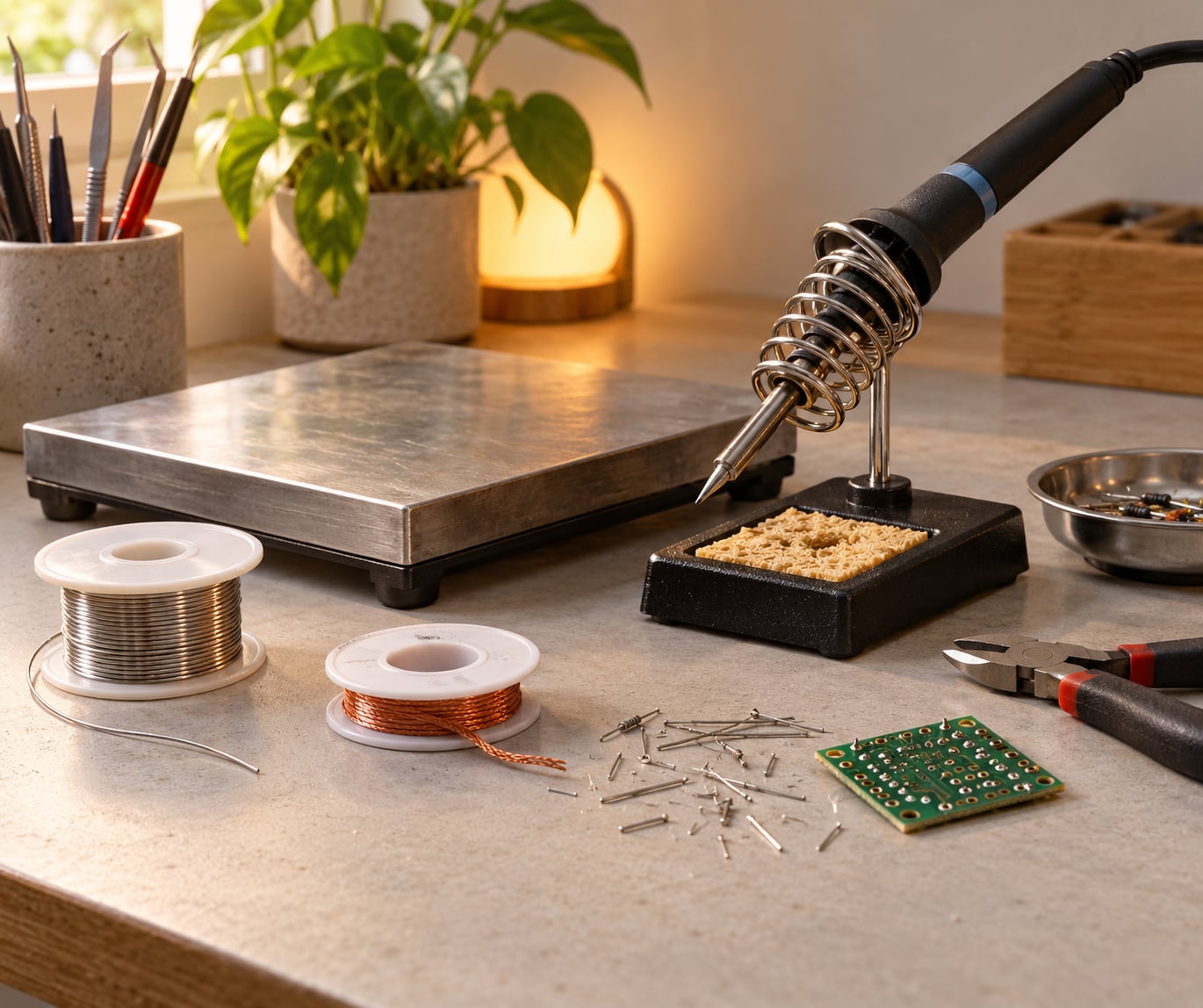
- Protect the surface. A steel bench plate or an old sheet of copper keeps solder off the bench and stops you sliding a hot iron onto whatever is underneath. Add a fume extraction arm if you will be working with flux regularly.
- Set the temperature and wait for stabilisation. A PID-controlled station shows a small oscillation as it hunts for setpoint; wait until that settles before judging anything. A cold tip that climbs slowly is a recovery problem, not a setting problem.
- Test on scrap. Melt a blob on a spare piece of board or a solder reel end. Good heat makes the blob spread quickly and wet the metal. Too cold and it sits, balls and takes forever; too hot and the surface skins over and fizzes while the underside stays un-wetted.
- Read the failure and adjust by small steps. Raise or lower the dial by 10-15°C (18-27°F) at a time. If solder melts but refuses to flow into the joint, the real problem is usually tip size or flux, not a further 20°C.
Common Temperature Problems and Fixes
Almost every soldering mistake shows up in the joint before it shows up in a failure report, and each symptom points at a specific cause rather than a general “too hot” or “too cold”.
Dull, grainy, or sand-textured joints usually mean the joint never got fully hot, or it was moved during the mushy phase. Bring the temperature up toward the top of the alloy’s range, match the tip to the pad, and hold still until the solder stops moving on its own. Flux does more for this than extra heat does.
Solder that balls up and sticks to the tip means the heat is going into the solder instead of the joint. The tip is too large for the pad, or the pad is on a ground plane pulling heat away. Drop to a finer tip, add a little flux, and give the joint a moment to soak before adding more solder.
Ground plane joints are the classic case. A pad tied to a large copper pour behaves like a heat sink, so the joint sits there and the operator keeps heating. There is no dial setting that fixes this quickly and safely. Use a wide chisel, fresh flux, and if the part allows it, spend a few seconds lifting the thermal weight of the pour with the iron before you make the joint.
Solder bridges and solder balls flying off are flux problems as much as heat problems. You burned the flux off before it could do its job, so add flux and work again at the same temperature rather than turning the dial up.
Overheated components, discoloured pads, or a lifted pad mean too much energy went in for too long. Check the datasheet for a maximum body temperature, drop the temperature, and switch to a larger tip that finishes the job in a shorter contact time.
A tip that will not take solder or has gone black is damaged or oxidised rather than mis-set. Clean it while hot with a damp sponge or brass wool, re-tin it, and only then judge the temperature. A tip that is not tinned cannot transfer heat properly at any setting.
One more on lead-free rework: re-melting a disturbed lead-free joint often fails because the surface oxidised the first time. Add fresh solder with new flux to the joint, melt it, then wick it away. The new metal carries the wetting for you, which is why experienced hands keep a length of leaded solder on the bench even when shipping lead-free work.
Safety and Component-Protection Basics
Ventilation is the first item and the easiest to get wrong. Flux fumes are the main inhalation risk in a hobby shop, so use local fume extraction rather than relying on a window. Wash your hands after every session, especially with leaded solder, and keep that solder away from food preparation surfaces.
On the lead question that comes up repeatedly: lead melts at 327.5°C (621.5°F), and your 63/37 solder is already fully liquid at 183°C (361°F) because the alloy melts well below its lead content’s melting point. Soldering temperatures are nowhere near lead’s boiling point of roughly 1,749°C (3,180°F), so the smoke coming off a joint is flux decomposition, not lead. The correct response is still to wash your hands and to check local rules before working with leaded solder in a commercial setting.
Heat-sensitive parts have their own ceilings that have nothing to do with solder. Many SMD LEDs are rated for a maximum soldering temperature at the body, MOSFET packages carry a specified limit, and connectors with plastic bodies can soften or distort. Read the datasheet for the specific part rather than generalising, and if the datasheet is unavailable, keep the iron low and the contact time short.
Battery work deserves its own caution. Lithium cells are damaged by heat well below soldering temperatures, so solder tabs and busbars with short contact times, clamp the cell away from the work, and never leave an iron unattended on a pack. Wear eye protection when soldering springs, cut leads or anything that can flick molten solder, and clear the bench before every session. Standards such as IPC-A-610 and J-STD-001 describe the workmanship classes that production work is judged against, and the hot-tip habits above are what those documents assume.
Frequently Asked Questions
What temperature should my solder iron be at?
For most electronics work, set a temperature-controlled iron to 350°C (662°F) for leaded solder and 370°C (698°F) for lead-free solder, then adjust from the joint. A large wire, a heavy terminal or a pad on a ground plane needs more, typically 400°C (752°F) or a wider tip. A small surface-mount LED nearby needs less. The dial is a starting point, not a decision.
What temperature does 60/40 solder melt at?
60/40 tin-lead begins to soften at 183°C (361°F) and is fully liquid at 191°C (375°F), so it melts across an 8°C (14°F) range rather than a single point. That mushy window is why 63/37 is preferred for fine work: it goes from solid to liquid with no in-between state, so a disturbed joint is easier to avoid.
What temperature do I set for lead-free solder?
Lead-free alloys such as SAC305 and tin-copper start at 350-370°C (662-698°F), which is roughly 20°C (36°F) hotter than you would use for leaded solder of the same joint size. Lead-free also has a wider pasty range, so hold the iron still and let the solder flow on its own rather than pushing it.
Is a higher soldering temperature better?
No. Higher heat is only useful for offsetting heat lost to a large thermal mass, and a wider tip delivers that energy faster than a hotter setting does. Running high burns flux off before it cleans the joint, oxidises the tip faster, and gives the component longer to overheat. Most common mistakes are made at too low a temperature with too small a tip.
How do I know when my iron is hot enough?
Test on scrap board first. The solder should melt quickly, spread to a shiny dome, and wet the pad rather than sitting as a ball that sticks to the tip. On a real joint, the pad and the lead should both reach temperature, after which the solder flows on its own. If it takes more than two or three seconds, change the tip size before the dial.
How hot should a soldering iron tip actually get?
The tip needs to be 100-150°C (180-270°F) above the solder’s liquidus so that heat loss to the joint, the lead and the board does not drag the working surface below melting point. That is why a station sits at 350°C (662°F) for solder that melts at 183°C (361°F). The tip itself is not the target; the joint is.
Start With a Conservative Setting and Adjust
Find out what solder you are holding, open the alloy row in the table above, and set the dial in the middle of that range: 350°C (662°F) for leaded, 370°C (698°F) for lead-free. Fit a chisel tip about as wide as the smallest pad you will touch, tin the tip, and let the station settle.
Then make one joint on scrap and read it. Fast melt and a wet, slightly domed surface means your heat is right. Slow melt means more heat, a bigger tip, or less thermal mass to fight. A joint that skins over and fizzes means you are too high or too slow.
That is the whole method behind soldering iron temperature basics explained: pick the alloy, start in its range, match the tip to the joint, and let the finished joint tell you what to change next.