To test a diode with a multimeter, turn the dial to diode test mode, hold the red probe on the anode and the black probe on the cathode to read the forward voltage drop, then swap the probes and check that the meter shows OL. A healthy diode gives one sensible number one way and blocks everything the other way. The whole job takes under a minute and tells you which of the three failure modes you have.
A diode is a one-way valve for current, and that valve can fail in exactly three ways: it can open, it can short, or it can leak. Each one looks different on the display, which is why the reading matters more than the beep.
Table of Contents
- What You Need
- Step-by-Step Diode Testing
- 1. Isolate the Diode and Identify Its Polarity
- 2. Select Diode Mode or Resistance Mode
- 3. Place the Probes Across the Diode
- 4. Read and Interpret the Measurements
- 5. Confirm the Diode Is Good or Faulty
- Common Mistakes and Troubleshooting
- Frequently Asked Questions
- Can I test a diode without removing it from a circuit?
- What diode-test reading means the diode is good?
- Should I use resistance mode or diode mode?
- Why does a good diode show a different reading in each direction?
- Can I test an LED, rectifier diode, or Schottky diode the same way?
- Conclusion
What You Need
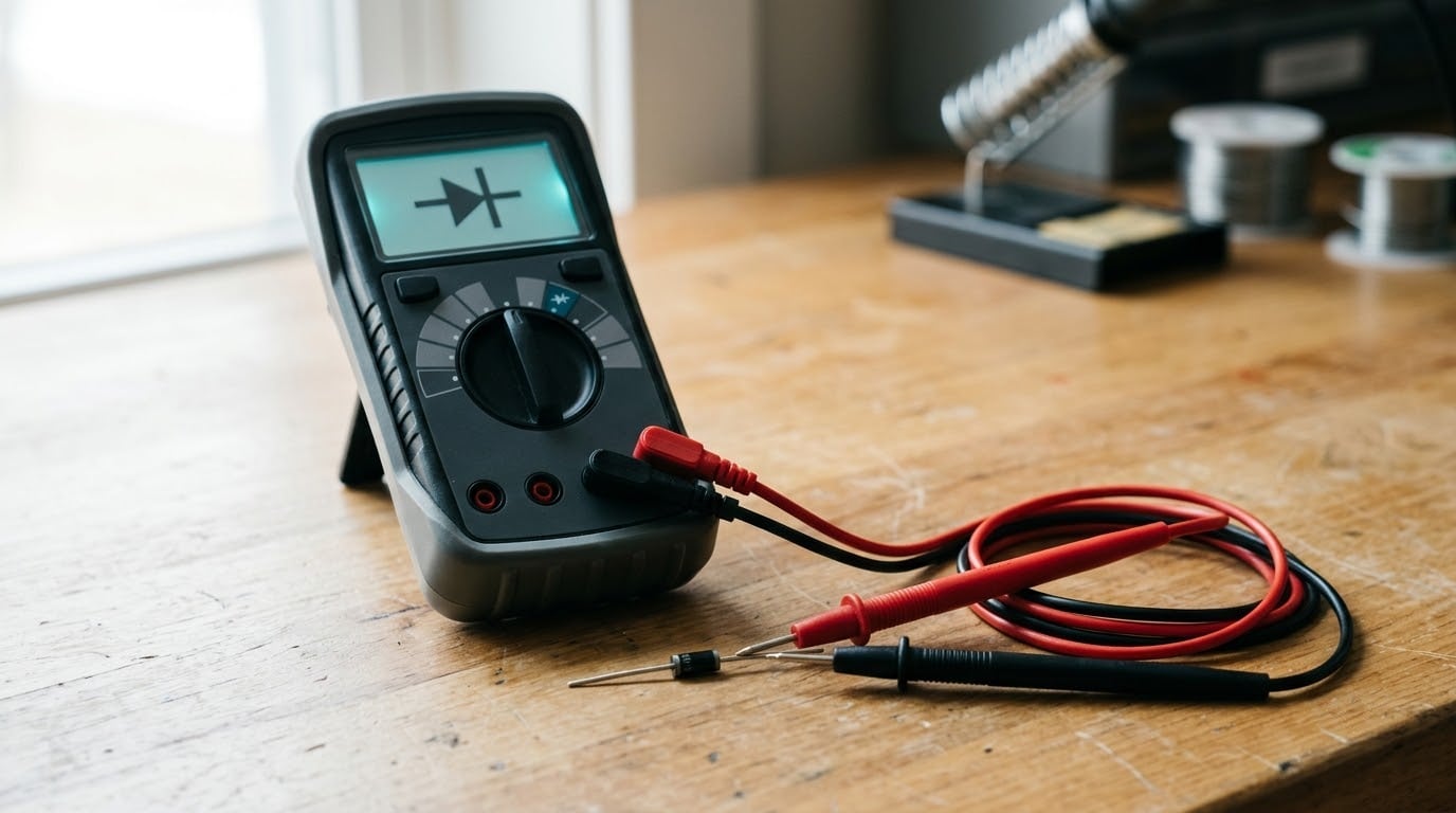
A digital multimeter with a diode test function is the only real requirement. Look for the diode symbol on the dial, a triangle pointing at a vertical line, next to the continuity and resistance settings. Most meters sold in the last decade have it, including the entry-level models.
You also want the diode itself, ideally desoldered or lifted on at least one leg, and about five minutes of clear working space. Keeping a meter in the bench drawer for years without opening the manual is not preparation, which is why we start with the symbol and the safety steps below.
Before you power anything on, remember what the diode check actually measures. Diode test mode pushes a small constant current, usually around 1 mA, through the part and measures the voltage that appears across it. That is why the display shows volts and not ohms, and why it gives you a forward voltage figure rather than a resistance.
Manual diode checking is also the cheapest first pass before anything more elaborate. When you need repeatable readings across many parts or full parametric data later, automated test equipment basics for beginners covers where a bench setup takes over.
Step-by-Step Diode Testing
1. Isolate the Diode and Identify Its Polarity
Turn the power off and confirm zero volts at the diode with the meter in DC voltage mode before you touch anything in resistance or diode mode. Charged capacitors on a power supply board can hold enough energy to give you a false reading or damage the meter, and Fluke makes the same point in its diode testing guide.
Next, find the cathode. On an axial diode it is the end with the painted band, and that band marks the cathode. On a schematic, the cathode is the side with the bar in the symbol. On an SMD package, the silkscreen outline on the board usually includes a line on the cathode side. Get this backwards and a good diode will read like an open one, which is the single most common beginner error.
Ideally lift one leg with solder wick or tweezers so the diode hangs free. If you leave it soldered, current can still flow through parallel paths on the board and produce a reading that belongs to the circuit rather than to the diode. We cover that in more detail under common mistakes.
2. Select Diode Mode or Resistance Mode
Turn the dial to the diode symbol. On many meters you also get a continuity beep in the same position, which is useful but not sufficient on its own. A beep tells you conduction happened; it does not tell you the forward voltage.
If your meter has no diode mode, resistance mode still works. Choose the range where the internal battery sits a volt or two above the expected drop, which on most analog-style meters means the R x1k range. For a 1N4148 signal diode or a 1N4007 rectifier, expect a few hundred ohms to a few kilohms forward and OL or an over-range indicator in reverse. The problem with resistance mode is that the reading is nonlinear and changes with the range, because each range applies a different internal voltage.
3. Place the Probes Across the Diode
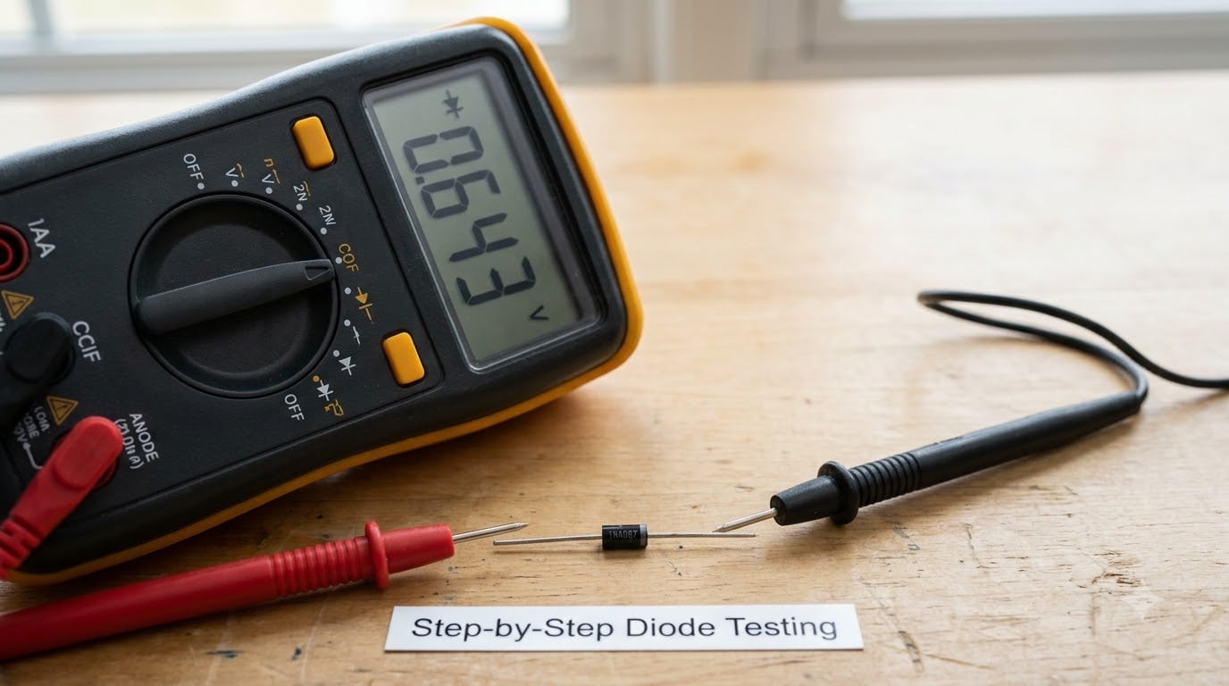
Put the red probe on the anode, the unmarked end, and the black probe on the cathode, the banded end. That forward-biases the junction. Hold the probes on until the reading settles; a fresh meter takes a moment to stabilise.
Write the number down, or at least remember it. Then swap the probes so red sits on the cathode and black on the anode, which reverse-biases the diode. Both readings together are the test. One alone is a guess.
4. Read and Interpret the Measurements
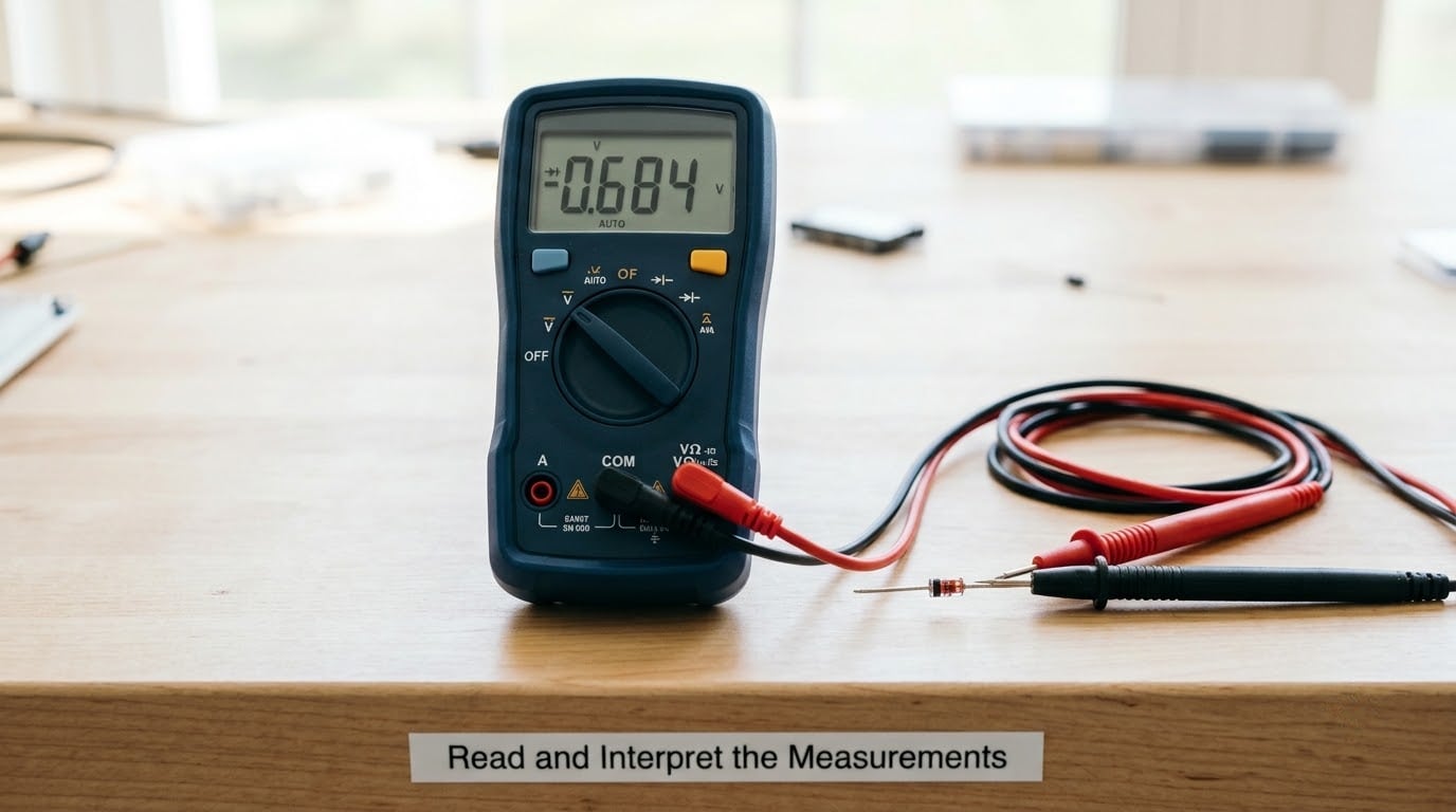
Here is the interpretation you will use every time. Above roughly 2 V, most meters show OL, meaning over-range.
| Forward reading (red on anode) | Reverse reading (probes swapped) | Verdict |
|---|---|---|
| 0.5 to 0.8 V for a silicon diode | OL | Good |
| 0.2 to 0.3 V for germanium | OL | Good |
| 0.15 to 0.45 V for Schottky | OL | Good |
| OL | OL | Open, replace it |
| Near 0 V | Near 0 V | Shorted, replace it |
| Normal drop | A few hundred kΩ or a small voltage | Leaky, replace it |
| Forward drop but no OL in reverse | OL | Likely still in circuit, lift one leg |
Expected forward drop depends on the device, and this is where a lot of second-guessing starts. Match the number to the part you are holding.
| Device type | Typical forward drop in diode mode | Notes |
|---|---|---|
| Silicon rectifier (1N4007) | 0.5 to 0.8 V | The 0.7 V figure everyone quotes comes from this class |
| Silicon signal diode (1N4148) | 0.5 to 0.8 V | Same junction physics, smaller package |
| Germanium | 0.2 to 0.3 V | Noticeably lower, worth checking before you call a diode bad |
| Schottky | 0.15 to 0.45 V | Low drop and fast recovery |
| LED | 1.2 to 3.5 V | Colour sets the figure; red sits near 1.8 V, blue and white near 3 V |
| Zener | 0.5 to 0.9 V forward | Forward test only; a meter will not show the breakdown voltage |
| Bridge rectifier | 0.4 to 0.9 V per junction | Test each of the four terminals against the others |
| Silicon carbide | 1.5 to 3.5 V | Higher than silicon, so a 3 V reading can be correct |
| TVS | 0.6 to 1.0 V forward | Two-way parts read as diodes in both directions |
Two honest limits worth knowing. First, diode mode pushes about 1 mA, so the voltage you read is not the drop the diode sees under real load; at higher current a silicon junction drops more. Second, the meter’s own offset puts the reading tens of millivolts off a true figure, which is why guitar pedal builders who need matched forward drops do not trust a DMM for this.
5. Confirm the Diode Is Good or Faulty
A good diode passes when one direction gives a drop that matches its type and the other direction gives OL. Anything else is a fault: OL both ways is open, near-zero both ways is shorted, and a measurable reverse reading is leakage that will get worse.
Before condemning a part, look at it. A cracked body, a burnt smell, discoloured terminals or a scorched board pad tells you the failure mode and may explain the rest of the damage. If the diode reads fine out of circuit but the fault persists, the diode was never the problem and you keep looking upstream.
Common Mistakes and Troubleshooting
Testing a diode that is still soldered in. This produces the most false results. Parallel traces and other junctions give the meter an easier path than the diode itself, so a good part can look leaky or a dead part can look alive. Lift one leg, and that is the whole fix. Retched put it plainly on All About Circuits: the traces on the PCB can cause false positives, so pull one end.
Leaving the board powered. Diode and resistance modes push their own current through the part. On a live board you are measuring the sum of the meter current and whatever the circuit supplies. Power off, unplug, then confirm zero volts at the diode before probing.
Trusting the continuity beep alone. Beeping one way only tells you the diode conducts one way. It says nothing about whether the forward drop is sane, which is exactly the difference between a healthy diode and one about to fail.
Reading 0.7 V as gospel. That figure is a typical silicon value, not a pass mark. A germanium diode at 0.3 V is fine, a Schottky at 0.2 V is fine, and a silicon diode sitting at 1.2 V forward is suspicious enough to investigate.
Confusing reverse leakage with a pass. A reverse reading of a few hundred kilohms is not a healthy silicon diode. Real silicon blocks almost completely; anything measurable is leakage, and under heat and bias it grows.
If you own an analog needle meter, the method is the same with two additions: zero the ohms on a fresh battery with the probes shorted, and remember the red probe is the negative terminal on most analog meters. Pick the R x1k range, touch the probes together, adjust the zero knob until the needle sits at zero ohms, then test the diode in both directions.
For bigger parts, two more tests earn their keep. A MOSFET has a body diode between drain and source, so a forward drop one way and OL the other is a pass on that junction. A bridge rectifier has four junctions, and testing each terminal pair against the other three catches the one that has failed.
Frequently Asked Questions
Can I test a diode without removing it from a circuit?
Sometimes, and the reading is useful when it shows OL in one direction. But a diode that is still soldered in can give a false result because current finds paths through other components on the board. For a verdict you can trust, desolder one leg so the diode hangs free with one terminal isolated. Testing in place works well for a quick sweep, as long as you treat a pass as provisional.
What diode-test reading means the diode is good?
A good diode reads a plausible forward voltage in one direction and OL in the other. For a silicon rectifier such as a 1N4007 or a 1N4148, expect 0.5 to 0.8 V forward and over-range in reverse. Germanium sits at 0.2 to 0.3 V and Schottky at 0.15 to 0.45 V. Two different readings are fine; two similar readings mean a fault.
Should I use resistance mode or diode mode?
Use diode mode whenever your meter has it. It pushes a constant current of roughly 1 mA and reports the resulting voltage, which is a repeatable number you can compare against a table. Resistance mode applies a different internal voltage on every range, and a diode is a nonlinear device, so the same part reads differently on different ranges. Use resistance mode only as a fallback.
Why does a good diode show a different reading in each direction?
A diode conducts forward bias and blocks reverse bias, so the two orientations should never match. Red on the anode and black on the cathode forward-biases the junction and you get a voltage drop. Swapped, the junction is reverse-biased and no current flows, so the meter shows OL above its roughly 2 V ceiling. If both directions read the same, the diode is shorted or leaky.
Can I test an LED, rectifier diode, or Schottky diode the same way?
Same procedure, different expected number. An LED shows 1.2 to 3.5 V depending on colour, so make sure the meter can reach that or you will see OL in both directions. A bridge rectifier has four junctions to test. A Zener can only be checked forward; a multimeter will not show its breakdown voltage. Schottky parts read low, so do not mistake 0.3 V for a fault.
Conclusion
Start by killing the power and proving zero volts at the diode, then find the cathode band so you know which way round the probes go. Switch to diode test mode, read the forward drop, swap the probes, and read again. That is the whole method.
One rule covers almost every case: two different readings mean good, two near-zero readings mean shorted, two over-range readings mean open, and any measurable reverse resistance means leaky. Once you have that habit, testing a diode with a multimeter stops being guesswork and becomes a ten-second check you can trust.