FR4 is a glass-reinforced epoxy laminate: woven fiberglass cloth impregnated with an epoxy resin binder and bonded to copper foil. It is the standard insulating substrate for rigid printed circuit boards, and the same ingredients in different resin-to-glass ratios produce everything from a hobbyist’s two-layer board to a ten-layer server board.
Most of what makes a PCB work well or fail early is decided before a single trace is drawn, in the laminate line of a fabrication drawing. The dielectric constant sets your impedance, the glass transition temperature sets your reflow margin, and the Z-axis expansion sets whether your plated through-holes survive assembly. This guide walks through what those numbers mean and where they stop being enough.
Table of Contents
- What Is FR4 PCB Material?
- What Does FR-4 Stand For?
- How Is FR4 PCB Material Made?
- From glass cloth to finished copper-clad laminate
- What Are the Key Properties of FR4 PCB Material?
- Dielectric constant and dissipation factor
- Moisture absorption and what it does to Dk and Tg
- Thermal expansion and via reliability
- Glass weave effect on signal integrity
- Which FR4 PCB Material Types Are Available?
- What Is the FR4 PCB Material Temperature Rating?
- Tg and Td are not the same number
- What Are the Advantages of FR4 PCB Material?
- What Are the Disadvantages and Design Limitations of FR4?
- How far you can push FR4 on RF and microwave designs
- How Does FR4 Compare With Other PCB Materials?
- FR-1, FR-2, FR-4, CEM-1 and G10: what the names mean
- How Do You Choose the Right FR4 PCB Material for a Design?
- How to write the material line on your fab drawing
- Frequently Asked Questions
- What is FR4 material in PCB?
- What are the disadvantages of using FR4?
- Is FR4 the same as G10?
- What is the difference between FR-1 and FR-4?
- Can FR4 be used for high frequency designs?
- What is the cost of FR-4 material?
- Conclusion: Start With the Operating Conditions
What Is FR4 PCB Material?
FR4 is the substrate material, not the finished board. The finished PCB is that laminate plus copper foil, drilled holes, plating, traces, solder mask and surface finish.
What Does FR-4 Stand For?
The designation is a NEMA classification, and it is worth decoding because the two characters tell you what the material is designed to do.
| Character | Meaning | What it implies for your board |
|---|---|---|
| FR | Flame Retardant | The resin system is formulated to self-extinguish, typically to a UL 94 V-0 rating |
| 4 | Material performance category | A higher category than FR-1 and FR-2, meaning better heat resistance, mechanical strength and insulation |
Here is the distinction that trips people up: FR-4 is a family of laminates, not a single material. A board labelled “FR4” could be a Tg 130 commodity core or a Tg 180 low-loss grade, and the two behave very differently in an oven and on a high-speed link.
How Is FR4 PCB Material Made?
From glass cloth to finished copper-clad laminate
The process starts with fiberglass woven into cloth in styles such as 106, 108 or 2110, where the style number roughly tracks thread count and therefore how much glass ends up in the finished laminate. The cloth is impregnated with epoxy resin and partially cured into prepreg, a tacky B-stage sheet that will fully cross-link under heat and pressure.
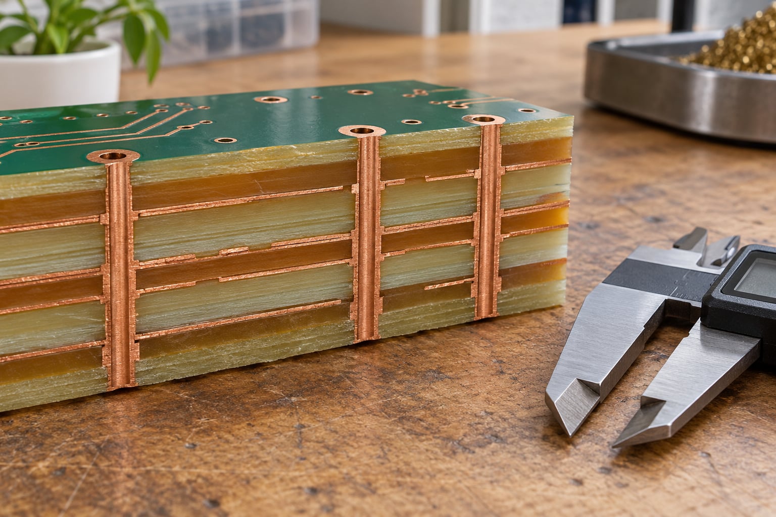
Thicker cores are built differently: layers of prepreg and glass are stacked and pressed on their own, without copper, to form a core sheet. Cores get drilled and copper-plated first, then combined with prepreg and copper foil in a lamination press, where the resin goes from B-stage to a fully hardened state at roughly 150 to 180 degrees Celsius and several hundred psi.
Copper weight and finished board thickness are independent choices that engineers routinely conflate. One ounce of copper is about 0.035 mm, so 1 oz outer and inner layers add roughly 0.035 mm per layer. The common 0.062 in (1.6 mm) board is the industry default, chosen because JEDEC footprints and most component packages were dimensioned around it, not because the material demands it.
After lamination the panel is drilled, holes are plated, outer copper is imaged and etched, and the surface gets a finish such as ENIG, immersion silver, OSP or HASL. Drilling quality is a material question in disguise: glass-rich laminates drill cleanly but can resin-smear, while high-resin-content prepregs absorb more energy and are gentler on the bit but can wick more moisture.
What Are the Key Properties of FR4 PCB Material?
The properties below are the ones that change design outcomes. Every value is a typical range for a mid-grade FR-4 laminate, and the spread is real: two suppliers quoting the same nominal Dk can differ by more than the tolerance your impedance stackup assumes.
| Property | Typical value | Test condition | Why it matters |
|---|---|---|---|
| Dielectric constant (Dk) | 4.2 to 4.8 | 1 GHz, IPC-TM-650 | Sets trace width for a given impedance target |
| Dissipation factor (Df) | 0.015 to 0.025 | 1 GHz, IPC-TM-650 | Converts to insertion loss per metre on long traces |
| Glass transition temperature (Tg) | 130 to 180 degrees C | DSC or TMA | Headroom between reflow peak and material softening |
| Decomposition temperature (Td) | 300 to 340 degrees C | TGA | Thermal stability ceiling, well above Tg |
| Z-axis CTE | 14 to 18 ppm/degrees C | Below Tg | Via stress during reflow and thermal cycling |
| X-Y CTE | 14 to 18 ppm/degrees C | Below Tg | Board dimensional change over a large panel |
| Thermal conductivity | About 0.3 W/m·K | Through-thickness | Heat has to leave through copper planes and vias |
| Tensile strength | Around 300 to 400 MPa | Machine direction | Handling strength, drilling and routing stress |
| Flexural strength | Around 400 to 500 MPa | Flat-wise at ambient | Resists bending and board flex during assembly |
| Insulation resistance | 1012 ohm or higher | ASTM D150 | Leakage between conductors at high humidity |
| Water absorption | 0.1 to 0.3% by mass | 24 h boil or 24 h at 23 degrees C | Shifts Dk, drops Tg, causes delamination risk |
| Flammability | UL 94 V-0 | UL 94 vertical burn | Assembly-level fire requirement |
Dielectric constant and dissipation factor
Dk tells you how fast the signal travels through the laminate, and a controlled-impedance stackup is only as good as the Dk your fabricator actually uses. Df tells you how much of that energy the laminate turns into heat, which is why two boards with identical Dk can behave completely differently on a long 5 Gbps link.
Converting Df into something you can judge is straightforward. In FR-4’s useful frequency range, the approximate dielectric loss is 0.015 to 0.020 dB per inch per GHz for a well-behaved laminate, so a 150 mm trace on a 4.2 Dk core at 3 GHz sits in the neighbourhood of 0.6 to 0.9 dB before you count vias, solder mask and the transition losses on top. That number is fine for control signals and painful for a clock distribution network.
Moisture absorption and what it does to Dk and Tg
FR4 is hygroscopic, and this is the least discussed property on most datasheets. Epoxy is polar, so absorbed water bonds to it. As laminate takes on moisture in a humid warehouse or an unheated facility, Dk rises and Df rises with it, which moves your impedance, and Tg drops, which eats reflow margin.
The practical consequences are unglamorous but real: store bare boards sealed with desiccant, bake boards before reflow if they have been out of controlled storage, and treat humidity as a variable in impedance-critical designs rather than an environment concern. Moisture is also the classic root cause behind delamination and conductive anodic filament failures, because it combines with ionic contamination under a bias field and grows a dendrite between conductors.
Thermal expansion and via reliability
FR4 expands far less than copper, roughly 15 to 18 ppm per degree Celsius against copper’s 17 to 18, and the mismatch is the whole story for via reliability. When a board goes through a 245 degree Celsius reflow, the copper barrel and the surrounding laminate want to expand by different amounts, and the resin is what has to absorb the difference.
Z-axis CTE is the number to watch. It rises sharply above Tg, which is why a high-Tg laminate gives a thicker-wall via more room to survive multiple reflows, and why two boards that pass assembly once can still fail in a field return that saw ten thermal cycles. Microvias are more exposed than through-holes because the aspect ratio is high and there is no barrel thickness to spare.
Glass weave effect on signal integrity
Glass and epoxy have different dielectric constants, roughly 6.5 for E-glass against 3.0 to 3.5 for the resin. In a woven laminate those two materials are interleaved in a regular pattern, so Dk is not uniform in all directions. The result is a periodic variation along a trace, known as the glass weave effect or fiber jitter.
On long parallel differential pairs, the two conductors can sit on different parts of the weave, which introduces a periodic skew into the differential impedance and shows up as jitter and mode conversion. If your design cares, ask the fabricator which glass style the material uses and align critical pair geometry with the weave, or move those layers to a low-loss material where Dk variation is smaller.
Which FR4 PCB Material Types Are Available?
Within the FR-4 family there are several practical variants, and the choice is usually driven by one constraint: how much heat the board sees and how much signal loss you can accept.
| Type | Key change | Benefit | Limitation |
|---|---|---|---|
| Standard FR-4 | Tg roughly 130 to 140 degrees C | Widest availability, lowest cost, every fab stocks it | Thin reflow margin, not ideal for lead-free on large boards |
| Mid-Tg FR-4 | Tg roughly 150 to 170 degrees C | Comfortable lead-free margin, better Z-axis CTE | Higher material cost, longer lead times from some mills |
| High-Tg FR-4 | Tg 170 degrees C and above | Reliable repeated reflow, fine for multilayer and automotive | Cost premium that rarely pays off on small low-layer boards |
| High-temperature FR-4 | Rated for sustained service near 200 degrees C | Suits power supplies, LED drivers and hot enclosures | Less flexible, more expensive, limited supplier base |
| Low-loss FR-4 | Lower Df resin system, often tighter Dk tolerance | Better insertion loss and jitter at multi-gigahertz speeds | Lower Z-axis CTE in some formulations, and a price jump |
| Halogen-free FR-4 | No brominated flame retardant | Needed for some environmental and automotive programmes | Higher cost, and some grades have lower Tg than their halogenated equivalents |
| Lead-free-compatible FR-4 | Tuned CTE and Tg for higher reflow peaks | Fewer failures in lead-free assembly | Costs more and does not remove the need for moisture control |
Named product lines are more useful than generic grades, because “high-Tg FR-4” still leaves a dozen valid options. Isola 370HR and Isola 185HR, Shengyi S1000, Ventec VT-47 and Kingboard KB-6066 all appear on real fab quotes, and each has a published datasheet you can hand to your fabricator instead of a vague adjective. If your design depends on a specific number, name the material on the drawing.
What Is the FR4 PCB Material Temperature Rating?
There is no single FR4 temperature rating. There are four different temperatures that designers routinely confuse, and the one on the quote is usually the least useful of them.
| Specification | What it measures | Typical FR-4 value | Design use |
|---|---|---|---|
| Glass transition temperature (Tg) | Where the resin softens and Z-axis expansion rises sharply | 130 to 180 degrees C depending on grade | Reflow margin, plating stress, thermal cycling life |
| Decomposition temperature (Td) | Mass loss under thermogravimetric analysis | 300 to 340 degrees C | Thermal stability ceiling; a safety margin number, not an operating limit |
| Lamination temperature | Press temperature used to build the board | About 150 to 180 degrees C at several hundred psi | Fabricator’s process window, not your component’s limit |
| Continuous operating temperature | Grade-specific service rating | Grade dependent, often near or above Tg | The number to use for enclosure temperature, not reflow |
Tg and Td are not the same number
Tg is where mechanical properties shift. Td is where the resin chemically breaks down, and for a good FR-4 it sits roughly 200 degrees above Tg. A board can be well past Tg and still not decomposing, which is why a Tg 140 laminate does not burn during a 245 degree reflow. What you have lost above Tg is stiffness and dimensional control, and that is what kills vias.
One more thing engineers complain about: laminate datasheets rarely state a maximum reflow temperature or a recommended cycle count. If that number matters for your assembly, ask the fabricator directly, and ask which reflow profile they qualified the material against. Over-specifying Tg on a small two-layer board costs money and buys nothing.
What Are the Advantages of FR4 PCB Material?
FR4 stays the default because the alternatives cost more and deliver less for the majority of designs.
It is inexpensive per unit of performance, and a commodity Tg 130 core is one of the cheapest engineered structural materials in electronics. It offers dimensional stability that holds fine features through etching, drilling and reflow, which is what makes controlled impedance and small trace-to-gap geometries practical at all. Mechanically it is strong, stiff and dimensionally repeatable in both axes.
Electrically it is a good insulator with high dielectric strength, and it is flame retardant to UL 94 V-0, which many assemblies require on paper even where a real fire is unlikely. Manufacturing is mature and forgiving: every fab in the world runs FR4, tooling is standard, and the whole SMT, AOI and reflow ecosystem is calibrated around it. Copper weights from 0.5 oz to 4 oz and thicknesses from 0.4 mm upward are all readily available, and high-layer-count builds in the tens of layers are routine.
The last advantage is unglamorous but real: when something fails on an FR4 board, the failure is usually a design or process problem you can find. The material is well characterised and its failure modes are documented.
What Are the Disadvantages and Design Limitations of FR4?
The honest answer is that FR4 is a good general-purpose dielectric with three specific weak spots: loss at high frequency, heat movement in the Z axis, and moisture.
Its dissipation factor of 0.015 to 0.025 is high next to low-loss laminates, so long high-speed traces attenuate. Dk varies with resin content, glass style, frequency and moisture, which makes tight impedance control harder than the nominal number suggests. Thermal conductivity of about 0.3 W/m·K is poor, so heat from a power device must leave through copper planes and thermal vias rather than through the laminate. Moisture absorption shifts Dk and Tg and drives delamination and conductive anodic filament risk. Glass weave effect adds jitter to parallel pairs on long routes.
It is also not flexible, not suited to extreme continuous temperature without a high-temperature grade, and it is a combustible composite once the copper and mask are in place, which is why a UL 94 V-0 laminate does not by itself give you a V-0 assembly. And it is simply not the right dielectric above roughly 1 to 2 GHz, where the loss numbers stop being a rounding error.
How far you can push FR4 on RF and microwave designs
Engineers working in RF and microwave design tend to agree on the practical boundary: FR4 is the cheapest and easiest material to work with, and it performs poorly once you are into the low-gigahertz range. Above a few hundred megahertz it is usable with careful short routing, matched launch geometry and attention to ground planes. Past a few gigahertz, the insertion loss and the temperature drift of Dk make it a liability.
Three mitigations are worth knowing before you switch material. Use a low-loss or mid-loss laminate only on the layers that carry the critical signal, and keep FR-4 cores for mechanical and low-speed layers in a hybrid stackup. Shorten the RF path by putting the RF device adjacent to the antenna or connector. And ask for a fab-supplied impedance coupon or a material datasheet with the actual Dk tolerance rather than working from a generic handbook value.
How Does FR4 Compare With Other PCB Materials?
Below are the substrates engineers actually choose between, and the condition that pushes them off FR4.
| Material | Temperature capability | Dk / Df at 1 GHz | Thermal performance | Dimensional stability | Typical use |
|---|---|---|---|---|---|
| FR-4 (glass epoxy) | Tg 130 to 180 degrees C | 4.2 to 4.8 / 0.015 to 0.025 | Low, about 0.3 W/m·K | Good, CTE about 15 to 18 ppm/degrees C | Nearly everything digital and low-speed analogue |
| CEM-1 | Lower class, paper reinforced | Around 4.5 to 5.5 / higher loss | Low | Fair, but dimensional drift with humidity | Simple consumer appliances, very cost sensitive |
| Polyimide | Broad, high-temperature grades | Around 3.2 to 3.5 / 0.002 to 0.005 low loss | Low, improves with copper heat spreaders | Good, lower CTE | High-speed, aerospace, flex and rigid-flex |
| Rogers and PTFE ceramic | Moderate to high, grade dependent | 2.2 to 3.5 / 0.001 to 0.002 | Low, laminator and assembly sensitive | Very good | RF, microwave, antenna, radar, 5G |
| Aluminium-based | Metal, heat limited by the dielectric | Set by the dielectric film | Excellent, carries heat across the whole board | Very high, near zero CTE | LED lighting, power conversion, compact high-current modules |
FR-1, FR-2, FR-4, CEM-1 and G10: what the names mean
The naming in this space is genuinely confusing, and even experienced engineers get it wrong. A useful summary:
| Name | Reinforcement | Resin | Class | Typical use |
|---|---|---|---|---|
| FR-1 | Paper or cotton web | Phenolic | Lowest | Appliance internals, low-voltage controls |
| FR-2 | Paper | Phenolic | Low | Similar to FR-1 with better heat resistance |
| FR-4 | Woven fiberglass cloth | Epoxy | High | Standard rigid PCB substrate |
| CEM-1 | Cellulose paper core with glass surface | Epoxy | Medium | Cost-driven consumer two-layer boards |
| G10 | Woven fiberglass cloth | Epoxy | High, different grade set | Structural and electrical insulating stock, some RF and industrial uses |
The short version of the two most confused pairs: FR-1 versus FR-4 is a reinforcement difference, paper or cotton against woven glass, and only FR-4 is suitable for modern multilayer boards. FR4 versus G10 is a grade and supply-chain difference rather than a chemistry difference, since both are glass fibre in epoxy, and G10 sits closer to a structural and RF-adjacent laminate rather than a standard copper-clad PCB material.
How Do You Choose the Right FR4 PCB Material for a Design?
Work through these in order, and the grade usually falls out on its own.
Operating temperature. Find the maximum ambient inside your enclosure and add the rise from your own components. If the laminate will sit above its Tg for extended periods, or the board sees repeated reflows on a large assembly, specify mid-Tg or high-Tg. If not, standard FR-4 is the right answer and you should not pay for more.
Signal speed and topology. Anything at or above gigahertz serial rates with long traces deserves a low-loss material or a hybrid stackup. At a few hundred megahertz of clock or control signals, standard FR-4 with a good stackup is fine. For RF, decide by frequency, not by hope.
Power and heat. With more than a watt or two of dissipation, the laminate is the thermal bottleneck, not the copper. Use heavy copper on the hot layers, pour planes on both sides, and stitch thermal vias. Aluminium-based material is the better answer when the whole board is a heat spreader.
Layer count and board size. Higher layer counts and larger panels raise the Z-axis stress on the stack, which pushes toward higher Tg and lower Z-axis CTE. A ten-layer board on Tg 130 material is a reliability question, not a preference.
Mechanical demands. Connector loading, mounting holes and press-fit hardware all pull on the laminate. High flexural strength grades and reinforced edges pay off here, and mechanical stress near a large hole is where cracks usually start.
Environmental exposure. Humidity, condensation, conformal coating and conductive dust all raise the stakes on moisture absorption and cleanliness. Salt spray and outdoor temperature swings add thermal cycling, which is again a Z-axis CTE problem.
Manufacturing process. Check the fab’s capability rather than assuming: layer count range, finished thickness window, copper weight range, minimum trace and space, minimum drill, and whether they hold the exact laminate you asked for. Last of all, confirm compliance requirements such as RoHS and REACH, and UL recognition if your assembly needs it.
How to write the material line on your fab drawing
“FR4” alone on a purchase order is an open invitation to substitution, because the name covers Tg 130 through Tg 180 and the fabricator will pick whatever is in stock. Specify enough to close that door. A workable material line reads like this:
NEMA FR-4, IPC-4101 compliant, Tg 170 degrees C minimum by DSC, 1 oz copper finished, 0.062 in (1.6 mm) nominal finished thickness, UL 94 V-0, laminate to be Isola 370HR or approved equivalent.
Add the surface finish, the impedance requirement with a tolerance and the governing fabrication standard, typically IPC-6012 Class 2 with IPC-A-600 acceptability. Then put one clause in the purchase order: no laminate substitution without written approval. Engineers who have been burned by a quiet swap from high-Tg to standard material consider that clause the most valuable line on the drawing.
One last piece of advice that forum threads keep circling back to: ask your fabricator for the Dk value and Dk tolerance of the specific laminate they will use, in writing, before you design the stackup. A 50-ohm line calculated from a generic handbook Dk can come off the fab line at 55 ohms, and no amount of careful geometry will fix it afterwards.
Frequently Asked Questions
What is FR4 material in PCB?
FR4 is a glass-reinforced epoxy laminate made of woven fiberglass cloth impregnated with an epoxy resin binder and bonded to copper foil. It is the standard insulating substrate for rigid printed circuit boards. The glass provides mechanical strength and dimensional stability, the epoxy insulates and self-extinguishes, and the copper carries the signal. A finished PCB is that laminate plus drilled and plated holes, traces, solder mask and surface finish.
What are the disadvantages of using FR4?
FR4 loses ground in four places: its dissipation factor of 0.015 to 0.025 is high, so long high-frequency traces attenuate; its thermal conductivity near 0.3 W/m·K is low, so heat must leave through copper and vias; it absorbs moisture, which raises Dk and lowers Tg; and the glass weave makes Dk anisotropic, adding jitter on long parallel pairs. It is also rigid, so it cannot serve a flex circuit.
Is FR4 the same as G10?
They are closely related but not interchangeable in practice. Both are woven fiberglass cloth in an epoxy resin, so the chemistry is similar. G10 belongs to a different grade set used more for structural insulating stock and some RF and industrial applications, and it is not supplied with copper foil through the standard PCB laminate supply chain. For a printed circuit board, specify FR-4 and name the manufacturer part number you want.
What is the difference between FR-1 and FR-4?
The difference is the reinforcement. FR-1 is a paper or cotton-web reinforced phenolic laminate, which gives it lower heat resistance, lower mechanical strength and lower insulation performance. FR-4 uses woven fiberglass cloth in an epoxy binder, which is why it has a much higher glass transition temperature and dimensional stability. FR-1 is used in simple appliance controls; only FR-4 is suitable for modern multilayer printed circuit boards.
Can FR4 be used for high frequency designs?
It depends on how high. FR4 works acceptably for RF in the low hundreds of megahertz with short routing, matched launches and solid ground planes. In the low-gigahertz range the dielectric loss and the frequency drift of Dk make it a poor choice for anything with a long RF path. Above a few gigahertz, specify a low-loss laminate such as Rogers or PTFE, or use a hybrid stackup with FR-4 cores and low-loss prepreg on the critical signal layers.
What is the cost of FR-4 material?
Standard Tg 130 FR-4 is one of the cheapest engineered materials in electronics, and it is commodity-priced because every fabricator stocks it. The cost drivers are the Tg grade, glass style and resin content, copper weight, panel size, and the quantity break. Mid-Tg and high-Tg add a modest premium, while low-loss, halogen-free and high-temperature grades cost considerably more because fewer mills make them. Board price follows material price, not the other way round.
Conclusion: Start With the Operating Conditions
FR4 is the right answer more often than any other substrate, and the wrong answer for a small set of well-defined conditions. Name the temperature range the board sees, the electrical performance it has to hold, the mechanical load it carries and the process that will build it, and the grade picks itself.
Then write that decision down on the fab drawing with enough precision that nobody can substitute a cheaper laminate without noticing. That single line is the difference between “FR4” the category and FR4 the material you actually designed for.