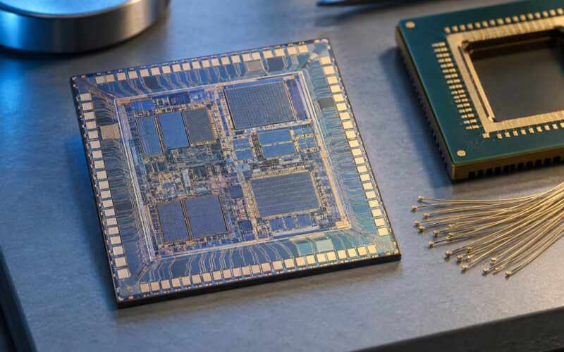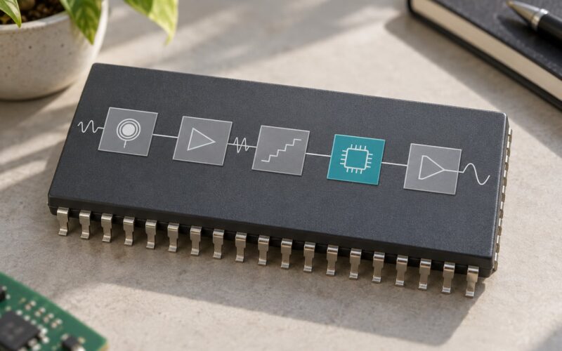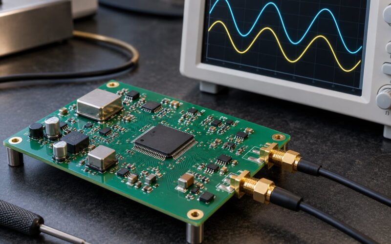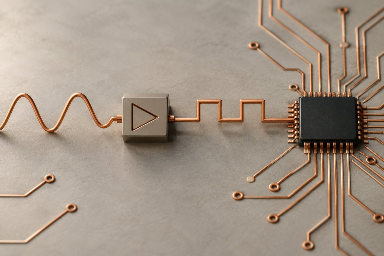
An analog chip works on a continuously varying voltage or current, where any value in a range is meaningful, while a digital chip works only on discrete logic levels it labels 0 and 1. That one difference shapes how analog chips differ from digital chips in signal handling, circuit design, power, noise, verification and cost.
The distinction matters more than it sounds. It decides which tools a designer opens, whether a block can shrink with each new process node, and how many engineers it takes to bring a product to market. It is also the line that separates a radio from the microcontroller inside it.
Table of Contents
- How Analog Chips Differ from Digital Chips at a Glance
- What Signals Do Analog and Digital Chips Process?
- How Do Analog and Digital Circuit Designs Differ?
- What Does the Keyword Analog Chips Differ from Digital Chips Mean in Practice?
- How Do Power, Noise, and Accuracy Affect Each Chip Type?
- Which Components and Tools Are Used?
- Where Are Analog and Digital Chips Used?
- How Do Analog and Digital Chips Work Together?
- Which Should You Choose?
- Frequently Asked Questions
- Are analog chips always less accurate than digital chips?
- What is the simplest example of an analog chip?
- Can a chip contain both analog and digital circuits?
- Why are analog chips more sensitive to noise?
- Is it harder to design analog or digital chips?
- What is the difference between a digital signal and an analog signal?
- Conclusion
How Analog Chips Differ from Digital Chips at a Glance
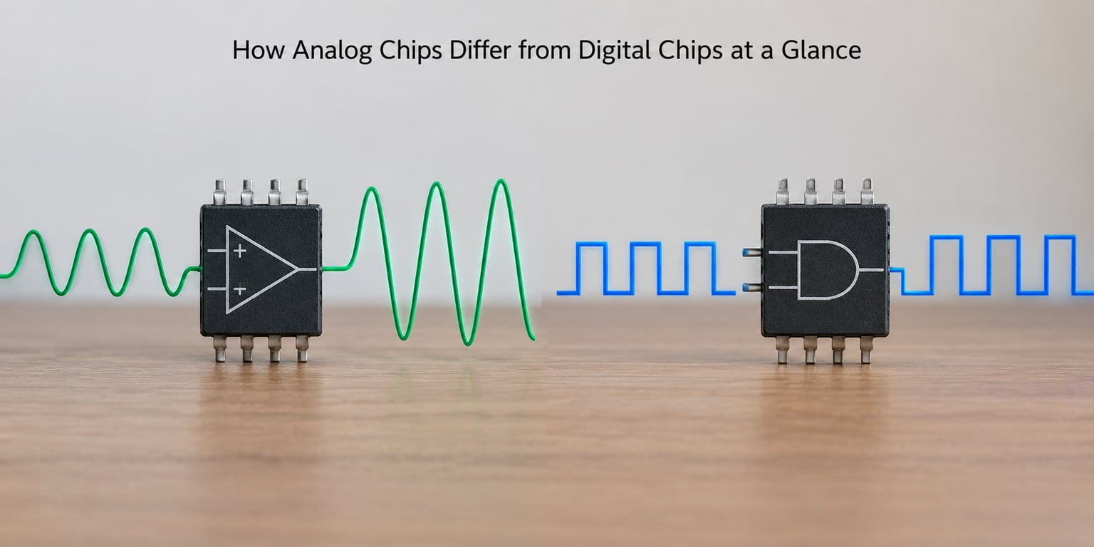
Two chip families share the same silicon and the same transistors, yet behave nothing alike. The table below sets the core differences side by side.
| Attribute | Analog chip | Digital chip |
|---|---|---|
| Signal representation | Continuous time-varying voltage or current | Discrete logic levels, 0 and 1 |
| Core building blocks | Operational amplifiers, comparators, resistors, capacitors, reference circuits | CMOS transistors combined into logic gates, flip-flops and registers |
| Circuit behaviour | Amplify, filter, shape, regulate; set by feedback | Boolean logic and sequential state changes; set by a clock and a truth table |
| Accuracy limit | Offset, drift, noise floor, settling time | Bit width, quantization, timing slack |
| Noise sensitivity | High, and errors are unrecoverable once amplified | Low, because the receiver only checks a threshold |
| Power behaviour | Mostly static draw, tied to bias current | Dynamic draw proportional to switching activity, plus leakage |
| Design and verification | Hand-tuned, simulated with SPICE, checked across PVT corners | Written in RTL, synthesised, placed and routed, timed with STA |
| Layout priorities | Symmetry, matching, isolation, guard rings, long matched routing | Density, wire length, timing closure, power and ground distribution |
| Scalability with process nodes | Limited, larger devices often preferred for matching and gain | Strong, density roughly doubles with each node |
| Typical uses | Sensor interfaces, audio, power management, RF, data converters | Processors, memory, storage, control logic, communications |
Read the last two rows together and you have the commercial story. Digital logic gets cheaper per function every generation; analog blocks do not, which is why a mature analog part often costs the same today as it did a decade ago.
What Signals Do Analog and Digital Chips Process?
An analog signal is continuous in both time and amplitude. A microphone output, a thermistor voltage, a blood-pressure sensor signal and a tuning-fork reference all move smoothly, and the exact value at any instant carries information.
A digital signal is discrete. The circuit only cares whether a node sits below or above a threshold, so a 0.61 V and a 0.59 V reading read identically if the threshold is 0.6 V. That deliberate loss of detail is what makes digital logic cheap to reproduce: the same binary answer appears on billions of chips.
The bridge between the two is quantization. An analog-to-digital converter samples a continuous input and maps it onto a fixed number of steps, and one step is called a least significant bit, or LSB. The gap between the true input and the reported value is quantization error, and it bounds how much an ADC can resolve no matter how quiet the analog front end is.
So why convert at all? Because computation is exact on digital values and approximate on analog ones. Once temperature, pressure or audio is turned into a number, a processor can filter it, log it, correct for sensor drift and transmit it with repeatability that no purely analog path can match.
How Do Analog and Digital Circuit Designs Differ?
Analog circuits are designed around feedback. An op-amp compares its inputs and adjusts its output until they match, which gives a circuit a defined gain that stays stable even as the transistor parameters move. Getting a stable gain means matching devices, choosing resistor ratios carefully, and compensating the loop for stability and settling time.
Digital circuits are designed around rules. A NAND gate has a truth table, not a waveform, and a flip-flop changes state on a clock edge. That makes the design describable in a language a synthesis tool can read, so the engineer defines behavior and lets tools pick the transistors, size the wires and place the cells.
The clearest way to see the split is the device size. Digital transistors are drawn as small as the process allows, because a smaller transistor is faster and cheaper. Analog designers often run the opposite instinct and use longer channel lengths and larger devices, since larger devices have lower output resistance, better matching and higher gain, and a device that matches its neighbour is worth more than a tiny one.
What Does the Keyword Analog Chips Differ from Digital Chips Mean in Practice?
In practice the comparison turns into four engineering decisions. First, what is the input: a physical variable that moves, or a set of logic decisions? Second, how much precision is required, and does the answer need to survive a temperature change? Third, where does the signal cross from the physical world into computation? Fourth, who fixes it, a person tuning a loop or a tool closing timing?
If the answer involves sound, light, heat, motion, pressure or voltage regulation, analog circuitry belongs somewhere in the path. If it involves counting, comparing, storing or deciding, digital logic is the cheaper route. Most real designs need both, which is why mixed-signal is the normal case rather than the exception.
There is one important caveat to the whole comparison. Digital chips are analog inside. Every digital transistor is a voltage-controlled device obeying analog physics, and its switching threshold moves with temperature, supply voltage and process variation. The 0 and 1 are a design convention layered on top, and they only work because designers leave enough noise margin between the rail and the threshold to survive PVT corners, meaning the process, voltage and temperature extremes of a part’s rated range.
How Do Power, Noise, and Accuracy Affect Each Chip Type?
Power behaves differently in each case. Analog blocks usually draw a near-constant current set by bias, so their consumption is predictable but hard to shrink; a high-linearity amplifier or a low-noise reference keeps burning power whether or not the signal changes. Digital blocks draw almost nothing while idle, then spike in proportion to how many transistors switch per clock cycle, which is why clock gating and power gating dominate power management in a processor.
Noise is where analog loses ground. Any unwanted voltage, current or temperature drift added to a small signal counts toward the result, and once that error is amplified it cannot be removed later. A sensor reporting 1 mV of noise on a 1 V signal is 0.1 percent accurate before the converter even runs. Digital receivers can ignore most of that, because a signal 200 mV above threshold is a 1 whether it arrived noisy or clean.
Accuracy also has a different shape. Analog precision is measured against a physical ideal, so it is quoted as offset, drift and noise figures and it degrades slowly with temperature. Digital accuracy is measured in bits, and it is fixed at design time: a 12-bit converter has 4096 steps, and adding silicon cannot add bits to it, only make each step cleaner.
Layout amplifies the difference. Analog routing is about symmetry, isolation from switching neighbours and long parallel matched paths, with guard rings and quiet supplies treated as part of the circuit. Digital layout is about density, wire length, timing and distributing power across a large array, and the two styles fight each other when they share a die.
Neither is universally better. Digital gives repeatability and cost per function; analog gives access to the physical world. Choosing well means matching the circuit to the variable being measured, not picking a side.
Which Components and Tools Are Used?
Analog teams start from a foundry’s process design kit, a library of characterized models for every device option, and a schematic. Simulation is SPICE-based, run across PVT corners and Monte Carlo mismatch runs, then repeated after parasitic extraction on the real layout, with layout versus schematic checking confirming the two match. Signoff includes reliability and EMIR analysis for the analog blocks.
Digital teams start from RTL in Verilog or SystemVerilog and move through synthesis into place-and-route, then verify with static timing analysis, formal equivalence checking between RTL and netlist, and functional simulation. Design for test structures, scan chains and memory BIST are inserted automatically, which is how digital parts reach very high test coverage.
That test difference shows up in the field. Industry reporting consistently finds analog content behind a large share of test failures and returns, because a digital defect usually flips a bit decisively while an analog defect shows up as a slightly wrong gain, a drifting reference or an offset that only appears at temperature extremes. High coverage on digital logic does not help a mismatched resistor pair.
Mixed-signal verification sits between the two, simulating the converter and the analog loop alongside the digital model, and checking isolation between switching domains on silicon, since crosstalk from a fast digital edge is a common cause of a converter that passes on the bench and fails in the enclosure.
Where Are Analog and Digital Chips Used?
Analog shows up wherever a physical quantity has to be measured or driven: sensor interfaces for temperature, light, pressure and motion; audio amplification and headphone drivers; voltage regulators, load switches and battery charging; RF front ends, mixers and power amplifiers; clocks and references; and the data converters that feed and drain the digital side.
Digital shows up wherever a decision has to be made or data has to be moved: microprocessors and SoCs, microcontrollers, memory, storage controllers, display drivers, network interfaces, encryption engines and the protocol logic inside a radio.
One of the clearest examples is a phone. The microphone signal is analog, so a codec front end conditions and converts it, a digital audio pipeline runs filters and mixing, and a DAC plus amplifier drives the speaker. Power management is mixed-signal too, with analog control loops setting the rails that digital logic then burns through.
Control systems follow the same pattern. A thermostat senses temperature, converts it, runs a control algorithm digitally, then drives a valve or heater through an analog power stage.
How Do Analog and Digital Chips Work Together?
Mixed-signal design is the normal case in a modern SoC, and the conversion boundary is the interesting part. A sensor produces a voltage, a buffer and filter chain conditions it, an ADC turns it into a number, and the digital block computes with it. Coming back the other way, a digital result feeds a DAC or a PWM stage and an analog driver sets the real-world output.
Other mixed-signal blocks follow the same idea. A phase-locked loop is an analog phase detector and charge pump wrapped around a digital counter. A SerDes PHY is an analog transmit and receive front end bolted to digital encoding logic. Even a microcontroller has analog blocks: its ADC, comparators, bandgap reference and oscillators are the physical interface that the digital core uses to talk to the outside.
That interface is where the two design cultures collide. A digital team can close timing and hand the block off, but the analog side still needs quiet supplies, guard rings and isolation from switching neighbours to hit its noise target.
Which Should You Choose?
Choose analog when the input is a continuously varying physical quantity, when the output must drive a real load such as a speaker or a motor, when the required precision is expressed as noise, offset or linearity, or when the block must work across a wide temperature range without recalibration. Reference designs, amplifiers, regulators and RF parts all fall here.
Choose digital when the job is logic, storage, counting or protocol handling, when the interface is already a logic level, when the accuracy requirement can be met by adding bits, or when the block has to scale across process generations. Processors, controllers and accelerators belong here.
Choose mixed-signal when a system must touch the physical world and compute, which is most sensors, wearables, industrial controllers and any SoC with a converter in it.
Before you commit, write down four things: the signal type, the accuracy you actually need, the physical interface, and where conversion happens. Most design disputes I have seen traced back to one of those four never being agreed on.
Frequently Asked Questions
Are analog chips always less accurate than digital chips?
No. Each type of accuracy is measured against something different. Analog parts are judged on offset, drift, noise floor and linearity, and a well-designed 16-bit converter front end can exceed the useful resolution of a 12-bit digital readout. Digital accuracy is fixed by bit width, so more bits mean more resolution but also more area and power. The right question is which error matters for the signal you are carrying.
What is the simplest example of an analog chip?
A resistive divider is the simplest analog circuit, since its output voltage varies smoothly and continuously with the input. A single operational amplifier configured as a buffer is the simplest analog chip, because it amplifies whatever voltage arrives and keeps every intermediate value intact. A voltage regulator is another familiar example. Any of these will happily pass a signal that a digital gate would simply reject as too small or too large.
Can a chip contain both analog and digital circuits?
Yes, and most do. A mixed-signal or analog mixed-signal part, often called AMS, contains analog blocks for interfacing with the physical world and digital blocks for computation and control. Every microcontroller includes an ADC, comparators, a bandgap reference and oscillators beside its digital core. Modern SoCs add data converters, clock circuits and SerDes blocks, all sitting on the same die.
Why are analog chips more sensitive to noise?
Because an analog output must preserve the magnitude of a signal, so any added disturbance becomes part of the result. A 1 mV error on a 1 V sensor reading stays 1 mV no matter what happens downstream. Digital receivers only test a threshold, so noise between the rail and the switching point is discarded. That threshold is exactly why digital logic keeps working next to switching power supplies while an analog amplifier next door struggles.
Is it harder to design analog or digital chips?
Analog is usually harder to verify and harder to fix late. Its behaviour is continuous, so it must be checked across temperature, supply and process corners and again after layout parasitics are extracted, and a mistake found at tapeout costs real money. Digital design is highly automatable, since synthesis and place-and-route handle most of the work and formal equivalence can prove the netlist matches the RTL. Practitioners on chip design forums consistently describe analog as the harder of the two.
What is the difference between a digital signal and an analog signal?
An analog signal varies continuously in time and amplitude, so every value in a range carries meaning, like a microphone voltage. A digital signal takes only a few defined values, usually logic levels labelled 0 and 1, and everything between those levels is treated as the same state. The real world is analog, so a system that must both measure and compute converts between the two at defined boundaries using an ADC and a DAC.
Conclusion
Analog chips carry the continuous world; digital chips carry decisions. Everything else, from noise tolerance to how a design is verified and what it costs, follows from that one split, with the reminder that digital logic is analog physics with a threshold layered on top.
Before choosing a path, identify four things: the type of signal, the accuracy actually required, the physical interface, and where the conversion boundary sits. Get those right and the choice of analog, digital or mixed-signal design makes itself.