The gain-bandwidth product is the gain an amplifier offers multiplied by the frequency range it can deliver that gain over. Multiply the two and you get a number, usually in hertz, that stays roughly constant for a given part. That single constant sets the trade-off every analog designer eventually runs into: you can have gain or bandwidth, and the product fixes what you get of each. The details of where the number comes from, and where the rule quietly breaks down, are worth working through properly. I have refreshed the notes behind this guide for 2026.
Table of Contents
- Gain Bandwidth Product at a Glance
- What Is Gain Bandwidth Product?
- The one-line formula and what each term means
- Why bandwidth is quoted in hertz, not radians per second
- Why the product stays roughly constant
- Where the constant comes from: the compensation capacitor
- What Does Gain Bandwidth Product Tell You About a Circuit?
- How Do You Calculate Gain Bandwidth Product?
- What Is the Difference Between GBW and Unity-Gain Bandwidth?
- How Does Gain Bandwidth Product Affect Circuit Performance?
- How Does It Apply to Analog, Mixed-Signal, and RF Chips?
- Why Might a Circuit’s Measured Gain Bandwidth Product Differ?
- Frequently Asked Questions
- Is gain bandwidth product measured in Hz or GHz?
- How is gain bandwidth product related to unity-gain bandwidth?
- Does a higher gain bandwidth product always mean a better amplifier?
- Why is the gain bandwidth product of an op amp given in Hz?
- Can gain bandwidth product determine a circuit’s settling time?
- Conclusion
Gain Bandwidth Product at a Glance
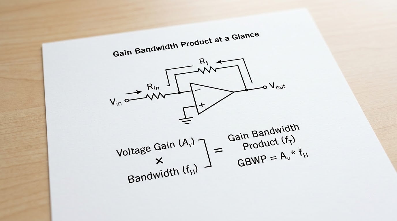
The gain-bandwidth product is a figure of merit for an amplifier, found by multiplying its gain at a given frequency by that frequency. For a single-pole amplifier the product holds roughly constant, so raising closed-loop gain lowers bandwidth by the same factor. It is written GBWP, GBW, GBP or GB, and it is quoted in hertz.
| Quantity | Symbol | Unit |
|---|---|---|
| Open-loop gain (DC) | AOL | V/V or dB |
| Closed-loop gain | 1/β | V/V |
| Closed-loop bandwidth | f-3dB | Hz |
| Unity-gain frequency | funity | Hz |
| Gain-bandwidth product | GBW | Hz |
| Dominant (break) frequency | fp1 | Hz |
That constant is the practical part. It is roughly the frequency at which the open-loop response of the part crosses 0 dB, which is why the number appears on nearly every op-amp datasheet.
What Is Gain Bandwidth Product?
Formally, the gain-bandwidth product of an amplifier is the figure of merit obtained by multiplying the amplifier’s gain at a given frequency by that frequency. In practice it is derived from the open-loop transfer function: gain at a frequency times that frequency. For a first-order response the result is independent of which frequency you pick above the break point, which is the property that makes the number useful.
The one-line formula and what each term means
GBW = gain at frequency × frequency. Take the open-loop gain of an amplifier at 10 kHz, convert it to an ordinary ratio if it was given in decibels, and multiply by 10,000. Do it at 100 kHz and you should get the same number if the part has a clean single-pole response.
Why bandwidth is quoted in hertz, not radians per second
Frequency response is often derived with angular frequency, since that is what the algebra falls out of. The difference is the familiar 2π factor: a pole at ωp rad/s sits at ωp/2π Hz. Datasheets convert back to hertz because that is the unit every other bandwidth in the design is written in, and comparing hertz to hertz avoids a factor-of-6.28 error.
Why the product stays roughly constant
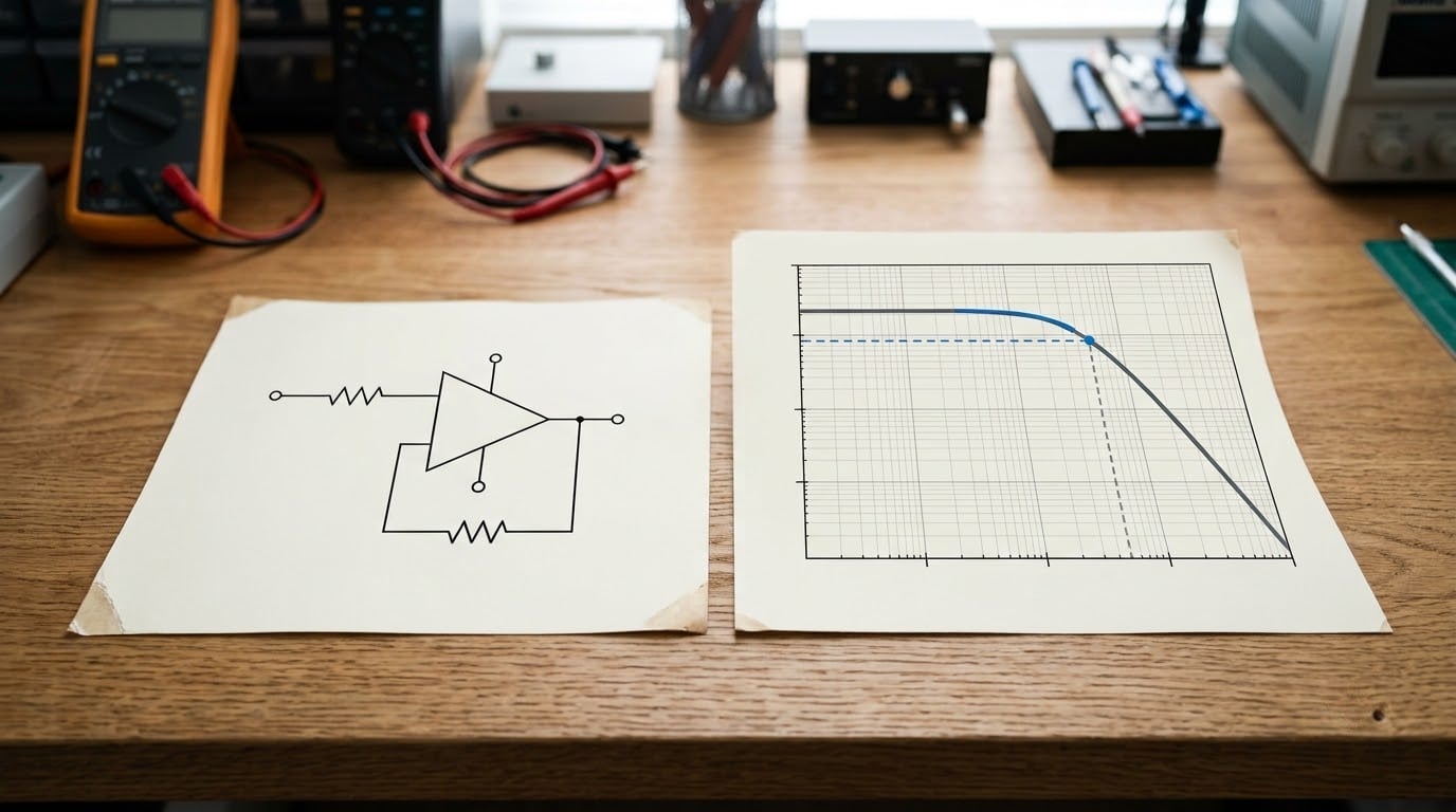
Open-loop gain falls as frequency rises, because internal capacitance limits how fast the circuit can respond. In a voltage-feedback op amp with one dominant pole, gain rolls off at 20 dB per decade. A straight line with constant slope on a log-log Bode plot means gain drops by a factor of ten for every decade of frequency, so gain times frequency cancels and the product stays fixed.
Where the constant comes from: the compensation capacitor
The dominant pole itself is created deliberately. A compensation capacitor across the second gain stage, combined with the Miller effect multiplying its apparent input impedance, sets that first break frequency. Designers pick this capacitor to trade open-loop gain against speed, so the gain-bandwidth product is a direct design decision rather than a law of nature. The result is the familiar family of curves: a high-speed part has low DC gain, a precision part has high DC gain and a narrow product. For a sense of where that fits in the wider chip context, see how analog chips differ from digital chips.
What Does Gain Bandwidth Product Tell You About a Circuit?
It tells you how much closed-loop gain you can have at a given bandwidth, and by extension what the circuit will do to speed, accuracy and noise. The relationship is not a law for every architecture, but for a compensated voltage-feedback amplifier the estimate is usually good to within a few percent, and it is often the first number checked in a design review.
Divide the product by the closed-loop gain you need and you get the approximate small-signal bandwidth. Three real cases illustrate how the budget behaves.
| Case | GBW | Closed-loop gain | Approx. bandwidth | Comment |
|---|---|---|---|---|
| Precision current monitor | 1 MHz | 101 | about 9.9 kHz | Fine for a slow sensor, useless for audio |
| Audio preamp stage | 10 MHz | 11 | about 900 kHz | Comfortable headroom to 20 kHz |
| Instrumentation front end | 40 MHz | 21 | about 1.9 MHz | Keeps flatness at 1 MHz |
| Wideband buffer | 200 MHz | 1 | 200 MHz | Bandwidth is the whole product at unity gain |
Notice the pattern in the second column. Speed, and therefore usable bandwidth, rises fast while DC accuracy falls. A 40 MHz part might have 10,000 V/V of open-loop gain; a 1 MHz part might have 1,000,000 V/V. You are choosing where the amplifier sits on that curve, not simply picking a fast part.
Noise works the same way, in reverse. A higher gain setting raises the signal level relative to the input-referred noise, which improves signal-to-noise for signals that are small. But the loop gain available at a given frequency drops as closed-loop gain rises, so noise that the amplifier would otherwise reject at the output is not rejected as well. The three effects pull against each other, and gain bandwidth product is the budget that pays for all of them at once.
How Do You Calculate Gain Bandwidth Product?
Work from the required signal bandwidth backwards, and the calculation is five steps.
1. Find the noise gain, not the signal gain. For a non-inverting stage the two are equal. For an inverting stage with input resistor Ri and feedback resistor Rf, the noise gain is 1 + Rf/Ri, which is higher than the signal gain. Sizing on signal gain is the most common sizing error in this whole area.
2. Convert any gain quoted in decibels to an ordinary ratio. A gain of 40 dB is not 40. It is 1040/20 = 100. This step catches people out constantly, and a dB figure dropped straight into the formula comes out wrong by orders of magnitude.
3. Multiply noise gain by the bandwidth you actually need. This gives the minimum unity-gain frequency the part must deliver.
4. Add margin. Sizing to the exact number leaves nothing for load capacitance, tolerance, temperature or the fact that datasheet GBW is usually typical rather than guaranteed. Two to three times is a common choice, and the analog and mixed-signal IP guide covers how that choice fits into a wider signal chain.
5. Check the large-signal limit next. A part can have ample GBW and still be unable to drive the required output amplitude quickly enough, which is a slew-rate question rather than a small-signal one.
A worked example: a sensor needs 50 kHz of flat bandwidth through a non-inverting stage at a gain of 41. The minimum unity-gain frequency is 41 × 50 kHz = 2.05 MHz. With 3× margin, the design needs roughly 6 MHz or more, so a 10 MHz part fits and a 2 MHz part does not.
To go the other way, and find the bandwidth from a known part, take a device rated at 20 MHz and configure it for a noise gain of 5. The estimated bandwidth is 20 MHz ÷ 5 = 4 MHz. If you work in radians per second instead, the same 20 MHz pole is 1.26×10⁸ rad/s, and the answer in hertz comes back to 20 MHz once the 2π is reapplied.
What Is the Difference Between GBW and Unity-Gain Bandwidth?
Unity-gain bandwidth is a measured frequency, and the gain-bandwidth product is a derived figure of merit. For a clean single-pole amplifier they are the same number. On anything more complicated they drift apart, which is the source of most of the confusion in forum threads about this topic.
| Amplifier type | Does GBW hold roughly constant? | GBW versus funity | How to size it |
|---|---|---|---|
| Single-pole voltage feedback | Yes | Identical | GBW divided by noise gain |
| Multi-pole voltage feedback | Approximately | Rated GBW often exceeds measured funity | Use the datasheet gain and phase plot |
| Current feedback | No | Not a meaningful comparison | Use the closed-loop bandwidth-versus-gain curves |
| Discrete transistor stage | No, until the fT limit | Not interchangeable | Use the full hybrid-pi model |
On a multi-pole part the high-frequency poles pull the open-loop response down faster than 20 dB per decade before it ever reaches 0 dB. The product quoted on the datasheet was often measured on a convenient intermediate frequency where the roll-off is still clean, so it reads higher than the frequency where closed-loop gain actually reaches one. The two numbers are not in conflict; they describe different things.
Current-feedback amplifiers break the framework entirely. Their bandwidth is set by a transconductance stage and a feedback resistor rather than by a compensated dominant pole, so bandwidth depends on closed-loop gain in the opposite sense to a voltage-feedback part and the roll-off is not 20 dB per decade. Applying the product rule to one gives wrong answers, and the datasheet gain and bandwidth curves replace the calculation entirely.
For the reference design context, our bandgap reference circuit guide shows a case where stability rather than bandwidth sets the pace, which is worth keeping in mind as you read the rest.
How Does Gain Bandwidth Product Affect Circuit Performance?
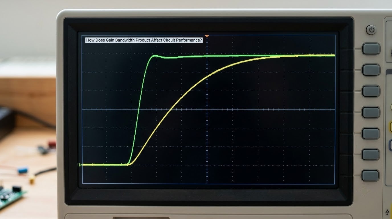
It sets a floor on how fast the output can react. For a first-order system the closed-loop bandwidth and the small-signal rise time are tied by one simple constant:
tr ≈ 0.35 / f-3dB
A stage with 4 MHz of bandwidth has a rise time of roughly 87 ns. That relationship assumes a single dominant pole, so it is a starting estimate rather than a promise, and additional poles, load capacitance and loop behaviour all stretch it.
Settling time follows from phase margin, which is itself a consequence of how much loop gain exists at the frequencies that matter. Tighten the feedback to raise closed-loop gain, and loop gain at high frequency falls with it, phase margin drops, and ringing appears before settling does. Chasing high open-loop gain and wide bandwidth at the same time is exactly how circuits end up oscillating.
Two bandwidth ceilings sit on the output. The small-signal ceiling comes from the gain-bandwidth product, and it applies to small signals at any frequency. The large-signal ceiling is full power bandwidth, set by slew rate divided by twice the peak output amplitude, and it applies only when the output swings far enough to be limited by that rate. A 10 V/µs part delivering 10 V peak can only manage about 500 kHz of full-swing output, even if its GBW says 100 MHz. The smaller of the two numbers is your real bandwidth.
Noise bandwidth is the other consequence. Integrated noise is collected across the full range where the circuit passes signal, so a wider closed-loop bandwidth passes more noise. Narrowing the gain to protect signal-to-noise directly costs bandwidth, and this is the same budget viewed from the noise side rather than the signal side.
How Does It Apply to Analog, Mixed-Signal, and RF Chips?
Everywhere a voltage-feedback amplifier sits, the same arithmetic applies, and the differences come from what the output has to drive.
Op amps and buffers are the direct case. A comparator is similar but usually faster and less precise, so the product rules the small-signal response while input and output overdrive recovery dominate the edges. A transimpedance amplifier uses the product in decibels with the noise gain expressed as 1 + Cin/Cf, which is often far higher than the signal gain and is where the sizing margin gets eaten. Sample-and-hold circuits add a hold capacitor that effectively adds another pole to the loop.
In converters, the buffer driving the reference or the input switch is frequently the limiting stage, and the amplifier is usually chosen against required settling rather than bandwidth. Filters, phase-locked loops and RF stages can each hit the same wall through a different door.
Beyond simple gain and bandwidth, gain bandwidth distance matters wherever drive strength changes: bootstrapped and gain-boosted stages, where capacitance and parasitic current set the usable signal swing and bandwidth. Where the load is reactive or lines are long, a full small-signal analysis beats any single product. Current-feedback parts want their gain and bandwidth curves. None of these fit neatly into one constant, and pretending otherwise is what leads to the datasheet surprises engineers complain about on support forums.
Why Might a Circuit’s Measured Gain Bandwidth Product Differ?
A measured value that does not match the datasheet is usually not a defective part. Several ordinary effects explain the gap.
Poles beyond the dominant one bend the response, so the product only holds near the break frequency. Finite output resistance and load capacitance add poles of their own, and a capacitive load on a voltage-feedback op amp can cut usable bandwidth sharply. Parasitic capacitance from layout, long traces and probe loading all pull the measured corner down. Process spread, supply voltage and temperature shift the internal compensation, which is why minimum and typical figures both appear on datasheets.
Gain-bandwidth enhancement techniques deliberately let the product vary with frequency, trading constant behaviour for higher speed. And the test setup matters more than most people expect: a measurement made at a different gain, supply or load than the datasheet test conditions is not comparable to the number on the spec line.
The practical rule is simple. Treat the datasheet product as a typical figure measured under stated conditions, size with margin, and confirm the design against the datasheet gain and phase plot for the gain you intend to use.
Frequently Asked Questions
Is gain bandwidth product measured in Hz or GHz?
The gain bandwidth product is normally quoted in hertz, and most op amps fall in the kilohertz to megahertz range, with precision parts at the low end and high-speed comparators in the gigahertz range. Gigahertz is used for the same quantity on faster devices. The units do not change the rule; a 10 MHz part and a 10 GHz part behave identically, they just trade DC gain for speed. Convert once, then work in one unit throughout the design.
How is gain bandwidth product related to unity-gain bandwidth?
For a single-pole voltage-feedback amplifier they are the same number. The open-loop gain falls 20 dB per decade, so the frequency where gain reaches one equals the constant product. On multi-pole parts the rated product is usually higher than the measured unity-gain frequency, because the extra poles steepen the roll-off before the crossing. On current-feedback amplifiers the product is not constant at all, so the datasheet gain and bandwidth curves replace it.
Does a higher gain bandwidth product always mean a better amplifier?
No. A higher product means more speed, and speed comes at a cost in DC gain, supply current, noise and stability margin. The right part is the one whose bandwidth, slew rate, noise and accuracy fit your signal, not the one with the largest number on the first spec line. A 1 MHz precision amplifier with high DC gain and low noise is a better instrument front end than a 200 MHz part used at the same gain. Match the part to the job.
Why is the gain bandwidth product of an op amp given in Hz?
Hertz is used because every other bandwidth in the design is written in hertz, from signal bandwidth to sampling rate, so a direct comparison is possible. The underlying derivation uses angular frequency in radians per second, and the two differ by 2. Poles and the product are converted back to hertz at the end to avoid a factor-of-6.28 error. Use radians per second only inside the algebra, and convert before comparing to a datasheet.
Can gain bandwidth product determine a circuit’s settling time?
Only indirectly. It sets the small-signal bandwidth, and rise time follows from that as roughly 0.35 divided by the bandwidth. Settling time depends on phase margin and damping, which come from the full loop response, not from the single product. A slow large-signal swing limited by slew rate can also set the settling time. For anything beyond a first-order estimate, read the settling time specification or simulate the actual loop.
Conclusion
The gain bandwidth product is a device constant that links the closed-loop gain you set to the bandwidth you get, and it is a good estimate for single-pole voltage-feedback amplifiers and nothing else.
Before treating it as the binding constraint, write down four numbers: the closed-loop gain you need, the noise gain of the topology, the signal bandwidth required, and the settling time target. Turn those into a minimum unity-gain frequency, add margin, then check slew rate against your output amplitude. The product tells you which part family you are shopping in, and the rest of the design tells you which part you actually want.